 Open Access Article
Gas barrier enhancement of uncharged apolar polymeric films by self-assembling stratified nano-composite films
Ali Akbar Motedayena,
Mohammadreza Rezaeigolestani a,
Carole Guillaumeb,
Valérie Guillard
 *b and
Nathalie Gontarda
aUMR IATE, INRA, 2 Place Pierre Viala, F-34060 Montpellier Cedex, France
bUMR IATE, University of Montpellier, 2 Place Pierre Viala, F-34060 Montpellier Cedex 1, France. E-mail: valerie.guillard@umontpellier.fr
First published on 9th April 2019
Abstract
The gas (O2 and CO2) permeability of an innovative stratified PE–organoclay (LLDPE/OMMT) nano-enabled composite films was studied for the first time and related to the self-assembly process driven by hydrophobic interactions. An 84.4% and a 70% reduction (i.e. a barrier improvement factor of about 6, sufficient for food packaging applications) were observed respectively in the oxygen and carbon dioxide permeability of the 5 bilayers coated film compared to the substrate, while only incorporating 2.4 v/v% of organoclay in the composite and increasing the thickness by 17.7%. Such drastic effect with so low amount of organoclays cannot be achieved by conventional melt blending/exfoliation of the clays into the polymer matrix and is due to a geometrical blocking effect of a brick-wall and compact layer structure of the impermeable clay tactoids. Mathematical prediction of oxygen barrier performance of PE/OMMT films has revealed that 12 bilayers would be necessary to further achieve a barrier improvement factor of 10.
1 Introduction
The packaging films sector is still seeking to improve the barrier properties of polymers whether they are petro- or bio-based.1,2 In the field of packaging materials for food and others bio- and perishable products, gas barrier materials play an important role to preserve bio-products quality and safety. Especially, the permeation of oxygen and carbon dioxide molecules often limits the shelf-life of sensitive products. Typically oxygen is responsible of oxidation phenomena as well as spoilage and pathogenic microbial growth and therefore oxygen deprived conditions within barrier packaging are necessary to maintain organoleptic and sensory properties as well as specific functionalities.3–6 Increasing the oxygen barrier properties is required for many conventional polymers with a very special challenge for eco-friendly bio-based plastics.7,8 It may be achieved by multi-layers (e.g. EVOH) or surface treatment (e.g. plasma) technologies.1,9 It has also been achieved by the use of barrier inorganic nano-fillers, such as montmorillonite (MMT) that is an abundant in the nature and low cost nano-particles (NP), which is particularly important for low value added food produces.10The introduction of barrier NP for the production of nano-composite materials have been mainly investigated by melt blending and processing.10,11 The main challenge for expressing the unique properties of NPs (such as mechanical, barrier, and fire retardant properties) in nano-composite blends, deals with the achievement of a sufficient exfoliation of NPs in the polymeric matrix. Partially exfoliated and intercalated structure is frequently observed.12–14 The possible level of NPs incorporation remains low, generally between 1 and 5 wt%.8 Such a low maximal NPs loading is due to the difficult dispersion of NPs in a polymer matrix despite chemical surface NP modification or the use of compatibilizers.8,15 Therefore the impact of NP dispersion in a polymeric matrix, on its barrier properties, is de facto auto-limited.10,16,17 In a composite material, the properties of each constituent can be better expressed when these constituents are structured into multilayered structures rather than homogeneous blends.18,19 A better resistance is offered to mass transfer when resistances are in series rather than in parallel.20 In this regard, the design of stratified alternate polymers and NPs layered structures, containing higher NP% and showing innovative properties related to NPs layers has been recently attracted a great interest.19,21 Among the different processing techniques that are used to fabricate multilayer nanocomposites, layer-by-layer (LbL) self-assembly is one of the most promising techniques that offers to achieve a layered structuring and stands out leading to a wide range of applications.22,23 LbL multilayer nanocomposites show improved properties compared to conventional blends and enable to reveal the proper properties of each layer, especially the NPs barrier properties.19,21,24
Generally, LbL films are produced by depositing alternating layers of oppositely charged materials with rinsing and drying steps in between. However, most of conventional polymers, but also promising bio-polymers that are commonly used as packaging materials are uncharged materials and LbL assembly cannot apply without sophisticated strategy such as ultrasonic, plasma and UV/ozone treatment of the substrate,25,26 which however, do not allow further successive deposition of uncharged substances layers. Non-electrostatic interactions have gained attention and recently, hydrophobic interaction and hydrogen bond,27 charge transfer interactions,28 host–guest interactions29 and metal–ligand coordination30 have been successfully investigated for LbL multilayer deposition.
Inspired by the concept of traditional LbL assembly, a novel method of hybrid non-ionic assembling of a system composed of repetitive bilayers of organoclays (OMMT) and polyethylene (PE) has been successfully developed.31 This novel methodology consisted of depositing OMMT on PE surfaces driven by solvophobic molecular construction involving hydrophobic interactions, and subsequently, the deposition of PE layers on the OMMT layers was the result of a dip-coating process involving physical sorption.31 Multilayered nanocomposites built up by this process represent a simple pathway to fabricate coatings with controlled coating thicknesses.
The objective of this work is to study, for the first time, the functional properties of a stratified hybrid nano-enabled composite films, previously developed using a novel self-assembly process.31 Gas barrier properties mainly to O2 and CO2, one of the most important functional properties related to the targeted packaging application, are assessed and discussed. The gases (O2 and CO2) permeabilities of the resulting films are studied as a function of the number of bilayers and the efficacy of the self-assembly process is discussed and compared to conventional nano-composites exfoliation and multilayer technologies.
2 Materials & methods
2.1. Materials
Linear low density polyethylene pellets (LLDPE, LL 1002YB, density 0.918 g cm−3, melt flow index (MFI), 2.0 g/10 min at 190 °C and 2.16 kg) were supplied by Exxon Mobil Chemical. Organoclay (Cloisite®20A – a natural montmorillonite modified with dimethyl-ditallow quaternary ammonium salt with a CEC of 95 meq./100 g clay mineral and a basal distance value d001 = 2.65 nm) was purchased from BYK additives & instruments (density: 1.77 g cm−3, moisture: <3%, typical dry particle size: <10 μm (d50)). Toluene (Sigma-Aldrich, USA) with a purity ≥ 99.7% was used as solvent. All other chemicals are analytical grade and used as received.2.2. Substrate film preparation
LLPDE substrate films were prepared by extrusion using a co-rotating twin screw extruder (Thermo Scientific™ EuroLab 16) with a L/D ratio of 40 and a screw diameter of 16 mm, at a screw speed of 200 rpm and a feeding rate of 1.0 kg h−1. The temperature profile of the extruder from feeder to the die was 160, 165, 165, 170, 170, 175, 175, 180 and 180 °C. The extruder was equipped with a plate die and was connected to calendaring system leading to films 160 μm thick and 10 mm wide.2.3. Multilayer build-up
As described in our previous work,31 a LLDPE solution (2%; w/v) was prepared by dissolving 2 g of LLDPE pellets (previously ground) in 100 mL of toluene at 120 °C for 3 hours under stirring. The temperature of the solution was then decreased to 80 °C prior to the layer deposition. Organoclay powder was also dispersed in toluene (2%; w/v) at ambient temperature for 60 minutes under stirring. The solubility of both solutions was checked through visual and/or microscopic observation of the solutions (clear solutions with no visible non-solubilized particles).LLDPE film substrates were cut in pieces of 100 mm × 30 mm and further rinsed with deionized water, methanol and again with deionized water before thorough hot air drying. Each substrate was then dipped in the organoclay dispersion for 2 s, taken out, thoroughly rinsed with toluene, and dried with hot air (100 °C, 120 s). The same procedure was then applied using the LLDPE solution instead of the organoclay dispersion. After this initial bilayer was deposited, the same deposition procedure was repeated until reaching the desired number of bilayers. A scheme of the self-assembly deposition technique and 3D cross sectional illustration of the resulting multilayer nanostructure are shown in Fig. 1.
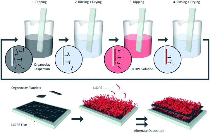 | ||
| Fig. 1 Scheme of the self-assembly deposition technique and illustration of the 3D cross section of the resulting multilayer nanostructure. | ||
2.4. Material characterization
 | (1) |
For total O2 and CO2 desorption and RH stabilization, materials were placed prior to measurements in the permeation cell with helium flux in both chambers.
2.5. Statistical analysis
Statistical analysis was carried out with SPSS 16 software. All data were analyzed statistically by one-way analysis of variance (ANOVA), and Duncan's multiple range test was used to compare the mean values. In all experiments, P < 0.05 was considered statistically significant.3 Results and discussions
3.1. Self-assembled structure characterization
The self-assembling procedure used in the present work as published in Motedayen et al.,31 consists in starting from an uncharged polymer substrate and repeated successive deposition of uncharged organoclay layer and uncharged polymer layer. Two different building blocks were first solubilized (for LLDPE) or dispersed (for the OMMT) in toluene at 120 and 20 °C respectively. The self-assembly of organoclays on PE surfaces was driven by solvophobic molecular construction involving hydrophobic interactions between the organic parts of the organoclay tactoids dispersed in an organic solvent and the LLDPE hydrophobic surface. The alternate variation of contact angle has confirmed the profilometry and the scanning electron microscopy results as well as the linear growth pattern, i.e. the successful highly stratified assembly of repetitive bilayers.31The surfaced and cross-sectional morphologies of the multilayer films prepared for the present study were observed by SEM in Fig. 2 and 3. Compare to the near surface of LLDPE, multilayers' surface are less smooth while homogeneous (Fig. 2). No crack, nor channel is visible on the surface suggesting a very good structural integrity. Increasing the number of deposited bilayers leads to more pronounced roughness as already observed in Motedayen et al.31 and ascribed to protrusions related to the incorporation of organoclay nanoparticles.
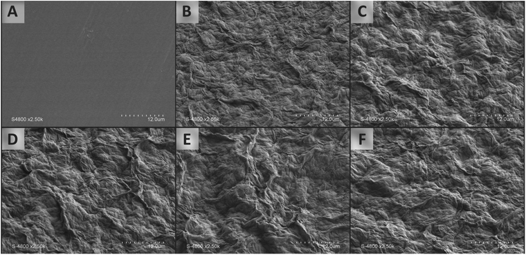 | ||
| Fig. 2 Surface morphologies of (A) the LLDPE film substrate, (B) 1 × OMMT/PE bilayer, (C) 2 × OMMT/PE bilayers, (D) 3 × OMMT/PE bilayers, (E) 4 × OMMT/PE bilayer sand (F) 5 × OMMT/PE bilayers. | ||
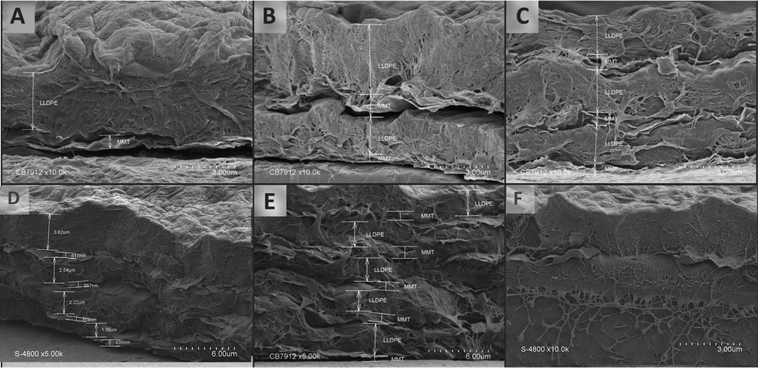 | ||
| Fig. 3 Cross section images of (A) 1 × OMMT/PE bilayer, (B) 2 × OMMT/PE bilayers, (C) 3 × OMMT/PE bilayers, (D) 4 × OMMT/PE bilayers, (E) 5 × OMMT/PE bilayers and (F) zoom on the OMMT layer. | ||
The cross-section images (Fig. 3) clearly confirmed a stratified repetitive structure with alternate flaky (OMMT) and compact (LLDPE) layers. The presence of voids between two adjacent layers (for instance in Fig. 3A or B) is ascribed to a retraction phenomenon of the first bilayers (as frequently observed for LbL assembly) due to the film cryo-treatment prior SEM observation.31
3.2. Film thickness
The thickness of deposited bilayers and thickness' growth percentage increased in the stratified composites with the number of bilayers (Table 1). Each layer's thickness was measured after removing the substrate from the organoclay dispersion/polymer, then rinsing and drying. Therefore, only stable layers that successfully pass both steps, were measured. The self-assembly deposition mode used to build-up these nano-enabled composite films results in a coating deposition on both sides of the LLDPE substrate. The thickness of the stratified hybrid composite films increased linearly with the number of OMMT/PE bilayers as previously observed.31 For each cycle, approximately 450 nm clay layer and 2.25 μm LLDPE are successively deposited resulting in a ∼2.6 μm film thickness increase (Table 1).| Number of deposited bilayers | 1 BL | 2 BL | 3 BL | 4 BL | 5 BL |
|---|---|---|---|---|---|
| a BL refers to the number of deposited bilayers on one side of the substrate film. % Growth refers to the thickness growth of the double-sided coated film. Thickness of LLDPE film substrate is 160 μm. | |||||
| Thickness (μm) | 2.24 ± 0.20 | 5.53 ± 0.43 | 7.97 ± 0.46 | 10.65 ± 0.52 | 13.74 ± 0.46 |
| % Growth | 2.8 | 6.9 | 9.9 | 13.3 | 17.7 |
Considering that the individual exfoliated organoclay OMMT used in this study is expected to display a thickness of about 4 to 5 nm,31 the deposited organoclay layer thickness measured in the present study suggested that a high number of clay platelets are deposited per cycle. Theoretically, there should be around one hundred stacked individual organoclays in one layer. However the microscopic observation of the organoclay layer Fig. 2F revealed that the layer is not an ideally planar deposition of organoclay entities and that their number seems to be much less important than calculated.
3.3. O2 and CO2 permeability
The oxygen permeability (OP) values of the neat PE film and hybrid multilayer-coated PE (double-sided coated) films measured at 20 °C and 0% RH are displayed in Fig. 4. The OP of the uncoated PE film is 1325.9 × 10−18 mol m−1 s−1 Pa−1, which is in agreement with reported OP values for LLDPE films in literature shown in Table 2.12,32–34 Remarkable decreases in OP with increased number of bilayers can be observed for the OMMT/PE coated PE substrates. The OP was 482.1 × 10⁻¹⁸ mol m−1 s−1 Pa−1 for the PE coated with 2 bilayers of OMMT/PE and as the number of bilayers increases to five, the OP value decreased to 205.3 × 10⁻¹⁸ mol m−1 s−1 Pa−1 (Fig. 4). The total 5-BL OMMT/PE assembly lowered the OP of the PE substrate by 84.4%, while only increasing the thickness by 17.7%.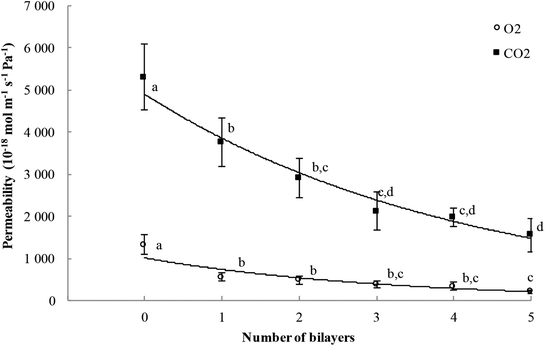 | ||
| Fig. 4 O2 and CO2 permeability values of hybrid multilayer-coated PE films as a function of the number of deposited bilayers (measured at 20 °C and 0% RH). Values with different letters are significantly different (P < 0.05). Original data could be uploaded at the following link: https://doi.org/10.15454/V91SS2. | ||
| Film composition | Processing | Permeability (×10−18 mol m−1 s−1 Pa−1) | Reference |
|---|---|---|---|
| a Data available for uploading at: https://doi.org/10.15454/ABUK3T. | |||
| HDPE | Melt | 223.2 | 51 |
| LDPE | Melt | 1138.4 | 32 |
| LDPE/2.2 v/v% Closite 15 A/3.9 v/v% EVA | Melt blended | 633.9 | |
| LLDPE | Melt/co-extrusion | 825.9 | 33 |
| LLDPE/1 v/v% Closite 20 A | Melt blended | 491 | |
| LLDPE/2.1 v/v% Closite 20 A | Melt blended | 326.3 | |
| LLDPE/3.2 v/v% Closite 20 A | Melt blended | 280.3 | |
| LLDPE/4.4 v/v% Closite 20 A | Melt blended | 254.9 | |
| LLDPE | Melt | 1794.6 | 12 |
| LLDPE/5 v/v% Closite 20 A | Melt blended | 803.5 | |
| LLDPE | Melt | 1857.1 | 34 |
| LLDPE/2.2 v/v% Closite 20 A | Melt blended | 1057.9 | |
| LLDPE | Melt/extrusion | 1325.9 | This study |
| LLDPE/0.54 v/v% Closite 20 A | Self-assembly | 558 | |
| LLDPE/1 v/v% Closite 20 A | Self-assembly | 482.1 | |
| LLDPE/1.5 v/v% Closite 20 A | Self-assembly | 375 | |
| LLDPE/1.9 v/v% Closite 20 A | Self-assembly | 343.7 | |
| LLDPE/2.4 v/v% Closite 20 A | Self-assembly | 205.3 | |
As for O2, the CO2 permeability (CO2P) values of the hybrid multilayer-coated PE films measured at 20 °C and 0% RH decreased with increasing the number of OMMT/PE bilayers compared to the pristine PE substrate. The CO2P of the uncoated PE film (5312.5 × 10−18 mol m−1 s−1 Pa−1) decreases to 2915.1 × 10−18 mol m−1 s−1 Pa−1 for the PE coated with 2 bilayers of OMMT/PE and as the number of bilayers increases to five, the CO2P value decreases to 1553.5 × 10−18 mol m−1 s−1 Pa−1 (Fig. 4). The total 5-BL OMMT/PE assembly lowers the CO2P of the PE substrate by 70%, while only increasing the thickness by 17.7%.
Montmorillonite inorganic clay are considered impermeable particles and as such decrease the gas permeability of either the polymer matrix it resides in, or the substrate on which it is deposited.10,24,35 In the multilayer nano-enabled composites studied, the OMMT platelets are not deposited as single platelets but organized in the form of tactoids containing about ten stacked platelets as evidenced by Motedayen et al.31 The gas permeability decrease (Fig. 4) showed that these tactoids are sufficiently well oriented to be create a brick-wall structure. The oxygen or carbon dioxide molecule permeating through this stratified composite film should diffuse taking the path of least resistance, opting for the long channels between tactoids (within the PE layers). Consequently, the O2 or CO2 molecule may travel perpendicularly to the diffusion direction, thus creating a longer path, slowing the transfer and reducing the permeability. A high degree of spacing between clay platelets (tactoids) and a preferred parallel conformation was previously reported to significantly decrease the gas permeability of LbL films.19,24,36,37 Because the permeating molecule is randomly rerouted perpendicular to its diffusion direction while traveling through these stratified assemblies (creating a nonlinear increase in diffusion length), the addition of OMMT/PE bilayers enhances drastically the barrier performance of PE substrate film.
Furthermore, the decrease in gas permeability may not only be caused by a geometrical blocking effect of a brick-wall structure of impermeable clay tactoids but also to a compact layer structure of the adsorbed multilayers due to strong interactions between building blocks. Poor packing of polymer's chain adjacent to the organoclay surfaces, is known to increase free volume of the interfacial polymer and thus to lower gas permeance.38,39 Moreover, strong polymer–organoclay interaction is known to reduce the polymer mobility and the oxygen penetration in the interfacial polymer layers.40 Therefore, the remarkable oxygen and carbon dioxide barrier properties of the developed stratified PE/OMMT films may be the result of both the increased tortuous path created by the impermeable organoclay platelets and of the highly dense film structure obtained by the self-assembly process.
Dispersing clay directly into a polymer matrix improves gas barrier of the bulk composite in a low extent, as highlighted in several recent papers.10,41–43 In the recent work of Wolf et al.,10 more than 700 values of gases permeability from the last 15 years' literature showed that the reduction of permeability by adding clay directly into a polymer matrix is capped at 50%. By comparison, LbL technology achieved and average reduction systematically higher than 99%.41 This gap in efficiency between isotropic blends and LbL or self-assembly process technology are easily explained by the nanocomposite structure achieved.
Permeability of the bulk nanocomposites is predicted to be a function of the aspect ratio of the filler and its orientation.44 The thickness of a single MMT platelet is roughly 1 nm, while the length is in the range of 200–500 nm.45 Because it is impossible to achieve a complete exfoliation of these high aspect ratio nanoplatelets in bulk nanocomposites, their effectiveness in reducing permeability values is limited46 as presented in Tables 2 and 3 for PE composites. Multilayer nano-enabled composites may display major advantages such as a larger contact area and a greater number of interfaces, able to better display the barrier effect of the used nanoclay.19,21,33,36
| Film composition | Processing | Permeability (×10−18 mol m−1 s−1 Pa−1) | Reference |
|---|---|---|---|
| a Data available for uploading at: https://doi.org/10.15454/FVKCHJ. | |||
| LLDPE | Melt | 4192 | 50 |
| LLDPE/2.48 v/v% Cloisite 25A | Melt blended | 2535.7 | |
| PE | Melt | 4241 | 49 |
| PE/2.48 v/v% Cloisite 25A | Melt blended | 2455 | |
| LLDPE | Melt | 7455.3 | 34 |
| LLDPE/2.2 v/v% Closite 20A | Melt blended | 4375 | |
| LLDPE | Melt/extrusion | 5312.5 | This study |
| LLDPE/0.54 v/v% Closite 20A | Self-assembly | 3763.4 | |
| LLDPE/1 v/v% Closite 20A | Self-assembly | 2915.1 | |
| LLDPE/1.5 v/v% Closite 20A | Self-assembly | 2120.5 | |
| LLDPE/1.9 v/v% Closite 20A | Self-assembly | 1982.1 | |
| LLDPE/2.4 v/v% Closite 20A | Self-assembly | 1553.5 | |
3.4. Barrier improvement factor
A useful tool to evaluate the barrier properties of composite films is the Barrier Improvement Factor (BIF), where BIF equals the permeability of pure polymer divided by the permeability of the composite (or coated substrate).47,48 As shown in Fig. 5A for oxygen permeability, the prepared 5 bilayers (BL) of OMMT/PE coating displays a BIF of 6.4 on PE, which is a significantly greater value than reported for bulk composites. Conventional melt blended bulk LLDPE/clay nanocomposites typically demonstrate a maximal BIF value of 3.24 at clay addition levels of 5 v/v% (0% RH, 23–25 °C).33 In the present study, a two times higher BIF (20 °C and 0% RH) was obtained with less than 2.5 v/v% of added clay (Fig. 5A). As a result, the low barrier LLDPE film, when coated with 5 bilayers of OMMT/PE, display better gas performance and a lower OP than neat high barrier HDPE film (Table 2). For CO2 permeability, conventional melt blended bulk LLDPE/clay nanocomposites generally represent at most a BIF value between 1.40 and 1.75 at clay addition levels of 2.2–2.5 v/v%, while the developed 5 BL of OMMT/PE coating in this study display a much higher BIF of 3.48 on PE at clay addition levels of 2.4 v/v% (Fig. 5B).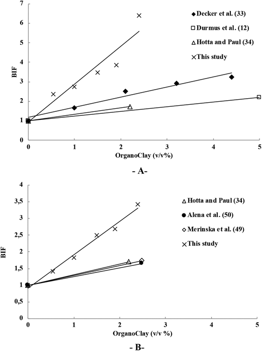 | ||
| Fig. 5 Barrier improvement factor (BIF) for, (A) O2 permeability and (B) CO2 permeability, of PE/OMMT composite films with different clay addition levels (v/v%). Literature data used for comparison are from ref. 12, 33, 34, 49 and 50. | ||
3.5. OMMT single layer permeability and prediction of multilayer O2 permeability
The oxygen permeability of one single clay layer was calculated using eqn (2), equation currently used for multilayer permeability calculations.52
 | (2) |
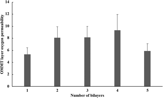
This OP value was calculated for each bilayer OMMT/PE system experimentally characterized and, as expected, was found to vary according to the position of the OMMT in the multilayered structure (Fig. 6). This could be related to the fact that the clay layers are not very homogeneously deposited and that the dispersion and orientation of the clay tactoids in the clay layers may vary from one layer to another. The PE layers and the interactions between the PE and organoclay layers may also affect the tortuosity of the materials and thus, the permeability of the bilayer.
The resulting average OP values found for one OMMT single clay layer in the multilayered material studied here was 7.37 ± 1.67 × 10⁻¹⁸ mol m−1 s−1 Pa−1. This value was only 7 folds higher than poly(ethylene-co-vinyl alcohol) (1.53 × 10⁻¹⁸ mol m−1 s−1 Pa−1), the best commonly used O2 barrier polymer for packaging. This value was about two folds lower than PET (1.19 × 10⁻¹⁷ mol m−1 s−1 Pa−1) and polyamide 6 (1.16 × 10⁻¹⁷ mol m−1 s−1 Pa−1), two other resins well known for their O2 barrier properties.53,54
Knowing the OP value for one layer of OMMT, the theoretical OP values of the multilayered structure could be calculated for increasing number of bilayers. This calculation has been performed and extrapolated to up to 20 bilayers using eqn (2), with 0.46 μm OMMT layer average thickness and an OP of 7.37 × 10⁻¹⁸ mol m−1 s−1 Pa−1. The LLDPE used as support has an average thickness of 160 μm, the inter-layer of PE has an average thickness of 2.3 μm and that LLDPE (substrate and interlayer) has an OP value of 1.33 × 10⁻¹⁵ mol m−1 s−1 Pa−1 (Fig. 7).
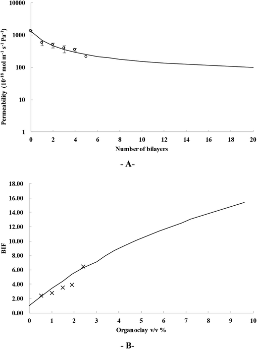 | ||
| Fig. 7 Calculated OP values (A) and BIF (B) for increasing level of bilayers and organoclay content. | ||
This approach enable to anticipate the impact of bilayers addition on OP value or in a reverse manner, to calculate the number of bilayers or organoclay content required to achieve a target BIF value. For instance, to reach a 10 BIF value, 12 bilayers would be necessary, i.e. 5.8 v/v% of organoclay added to the LDPE film support.
It must be highlighted that such BIF improvement was obtained by a self-assembly structure that involved only hydrophobic and solvophobic interaction mechanisms with no further need of sophisticated substrate pre-treatment or other processing additives such those used in traditional LbL assembly process based on electrostatic interactions (e.g. polyethylenimine, etc.). The self-assembly process used here could thus be applied to most of packaging materials which are conventional uncharged polymers. In addition, using only safe, non-toxic individual components without any further additives addition, the process is fully compatible with the safety constraints of the targeted application, i.e. to propose food contact material that obeys the EU regulation (see the Food Contact Materials-Regulation (EC) 1935/2004). Finally, the permeability reduction achieved of a factor 10 is perfectly in line with the targeted food packaging application, where a decrease by 10 of the permeability is often enough to fit the food requirement,55 while keeping low cost for the developed material (indeed very high barrier film are usually very expensive and unnecessary for most of food application, such as fresh food packed in modified atmosphere packaging).
4 Conclusion
The total 5-BL OMMT/PE assembly lowers the OP of the PE substrate by 84.4% and the CO2P of the PE substrate by 70%, while only increasing the thickness by 17.7% and incorporating 2.4% volume clay content. The O2 and CO2 barrier properties of the hybrid multilayer-coated LLDPE films were significantly better than those of the neat LLDPE substrate film. This reduction was much higher than blend nanocomposites containing a similar content of nanoclay. The increased tortuous path created by the deposition of impermeable nanoclay platelet layers between polymer layers in combination with a highly dense film structure obtained by the self-assembly process were responsible for these remarkable and unique barrier performance of coated LLDPE. Such an innovative structuring approach is likely to be applicable to others polymers provided an adjustment of the processing conditions that is under progress.Conflicts of interest
There are no conflicts to declare.References
- J. Lange and Y. Wyser, Packag. Technol. Sci., 2003, 16, 149–158 CrossRef CAS.
- K. Müller, E. Bugnicourt, M. Latorre, M. Jorda, Y. Echegoyen Sanz, J. Lagaron, O. Miesbauer, A. Bianchin, S. Hankin, U. Bölz, G. Pérez, M. Jesdinszki, M. Lindner, Z. Scheuerer, S. Castelló and M. Schmid, Nanomaterials, 2017, 7, 74 CrossRef PubMed.
- R. Sothornvit and N. Pitak, Food Res. Int., 2007, 40, 365–370 CrossRef CAS.
- C. Pénicaud, V. Guillard, S. Peyron and N. Gontard, Czech J. Food Sci., 2009, 27, S28 Search PubMed.
- Y. Michiels, P. Puyvelde and B. Sels, Appl. Sci., 2017, 7, 665 CrossRef.
- E. Chaix, O. Couvert, C. Guillaume, N. Gontard and V. Guillard, Compr. Rev. Food Sci. Food Saf., 2015, 14, 1–21 CrossRef CAS.
- A. Arora and G. W. Padua, J. Food Sci., 2010, 75, 43–49 CrossRef PubMed.
- S. Ray, S. Y. Quek, A. Easteal and X. D. Chen, Int. J. Food Eng., 2006, 2(4) DOI:10.2202/1556-3758.1149.
- K. Prasad, M. Nikzad and I. Sbarski, J. Polym. Res., 2018, 25, 1–20 CrossRef CAS.
- C. Wolf, H. Angellier-coussy, N. Gontard, F. Doghieri and V. Guillard, J. Membr. Sci., 2018, 556, 393–418 CrossRef CAS.
- C. Guo, L. Zhou and J. Lv, Polym. Polym. Compos., 2013, 21, 449–456 CAS.
- A. Durmuş, M. Woo, A. Kaşgöz, C. W. Macosko and M. Tsapatsis, Eur. Polym. J., 2007, 43, 3737–3749 CrossRef.
- P. Mederic, L. Le Pluart, T. Aubry and P.-J. Madec, J. Appl. Polym. Sci., 2013, 127, 879–887 CrossRef CAS.
- R. Sengupta, S. Chakraborty, S. Bandyopadhyay, S. Dasgupta, R. Mukhopadhyay, K. Auddy and a. S. Deuri, Polym. Eng. Sci., 2007, 47, 21–25 CrossRef.
- G. Choudalakis and a. D. Gotsis, Eur. Polym. J., 2009, 45, 967–984 CrossRef CAS.
- P. Judeinstein and C. Sanchez, J. Mater. Chem., 1996, 6, 511–525 RSC.
- G. D. Smith and D. Bedrov, Langmuir, 2009, 25, 11239–11243 CrossRef CAS PubMed.
- C. D. Mueller, S. Nazarenko, T. Ebeling, T. L. Schuman, A. Hiltner and E. Baer, Polym. Eng. Sci., 1997, 37, 355–362 CrossRef CAS.
- M. A. Priolo, D. Gamboa and J. C. Grunlan, ACS Appl. Mater. Interfaces, 2010, 2, 312–320 CrossRef CAS.
- J. Crank, The mathematics of diffusion, Oxford Science Publications, 2nd edn, 1980 Search PubMed.
- W. S. Jang, I. Rawson and J. C. Grunlan, Thin Solid Films, 2008, 516, 4819–4825 CrossRef CAS.
- G. Decher, in Multilayer Thin Films, Wiley-VCH Verlag GmbH & Co. KGaA, 2012, pp. 1–21 Search PubMed.
- M. Michel, V. Toniazzo, D. Ruch and V. Ball, ISRN Mater. Sci., 2012, 2012, 1–13 CrossRef.
- M. A. Priolo, K. M. Holder, S. M. Greenlee and J. C. Grunlan, ACS Appl. Mater. Interfaces, 2012, 4, 5529–5533 CrossRef CAS PubMed.
- S. Azlin-Hasim, M. C. Cruz-Romero, E. Cummins, J. P. Kerry and M. A. Morris, J. Colloid Interface Sci., 2016, 461, 239–248 CrossRef CAS PubMed.
- S. L. Wong, N. Ngadi and T. A. T. Abdullah, in Conference: 4th International Graduate Conference on Engineering Science & Humanity 2013, IGCESH 2013, 2013 Search PubMed.
- J. Zhao, F. Pan, P. Li, C. Zhao, Z. Jiang, P. Zhang and X. Cao, ACS Appl. Mater. Interfaces, 2013, 5, 13275–13283 CrossRef CAS PubMed.
- S. Y. Shimazaki and M. Y. R. N. Ito, Langmuir, 2001, 17, 953–956 CrossRef.
- A. Van der Heyden, M. Wilczewski, P. Labbé and R. Auzély, in Chemical communications, Cambridge, England, 2006, pp. 3220–3222 Search PubMed.
- X. Wang, Z. Jiang, J. Shi, Y. Liang, C. Zhang and H. Wu, ACS Appl. Mater. Interfaces, 2012, 4, 3476–3483 CrossRef CAS PubMed.
- A. A. Motedayen, C. Guillaume, E. Gastaldi, O. Félix and N. Gontard, RSC Adv., 2016, 6, 75640–75650 RSC.
- S. M. Ali Dadfar, I. Alemzadeh, S. M. Reza Dadfar and M. Vosoughi, Mater. Des., 2011, 32, 1806–1813 CrossRef.
- J. J. Decker, K. P. Meyers, D. R. Paul, D. A. Schiraldi, A. Hiltner and S. Nazarenko, Polymer, 2015, 61, 42–54 CrossRef CAS.
- S. Hotta and D. R. Paul, Polymer, 2004, 45, 7639–7654 CrossRef CAS.
- G. Laufer, C. Kirkland, A. A. Cain and J. C. Grunlan, ACS Appl. Mater. Interfaces, 2012, 4, 1643–1649 CrossRef CAS PubMed.
- G. Laufer, C. Kirkland, M. A. Priolo and J. C. Grunlan, Green Mater., 2012, 1, 4–10 CrossRef.
- K. M. Holder, M. A. Priolo, K. E. Secrist, S. M. Greenlee, A. J. Nolte and J. C. Grunlan, J. Phys. Chem. C, 2012, 116, 19851–19856 CrossRef CAS.
- A. J. Svagan, A. Åkesson, M. Cárdenas, S. Bulut, J. C. Knudsen, J. Risbo and D. Plackett, Biomacromolecules, 2012, 13, 397–405 CrossRef CAS PubMed.
- L. Xue, O. Borodin and G. D. Smith, J. Membr. Sci., 2006, 286, 293–300 CrossRef CAS.
- M. S. Hedenqvist, A. Backman, M. Gällstedt, R. H. Boyd and U. W. Gedde, Compos. Sci. Technol., 2006, 66, 2350–2359 CrossRef CAS.
- Y. Cui, S. Kumar, B. Rao Kona and D. van Houcke, RSC Adv., 2015, 5, 63669–63690 RSC.
- M. Krook, A. C. Albertsson, U. W. Gedde and M. S. Hedenqvist, Polym. Eng. Sci., 2002, 42, 1238–1246 CrossRef CAS.
- K. Yang, X.-L. Wang and Y. Wang, J. Ind. Eng. Chem., 2007, 13, 485–500 CAS.
- A. A. Gusev and H. R. Lusti, Adv. Mater., 2001, 13, 1641–1643 CrossRef CAS.
- J. H. Zhou, R. X. Zhu, J. M. Zhou and M. B. Chen, Polymer, 2006, 47, 5206–5212 CrossRef CAS.
- M. A. Osman, V. Mittal and H. R. Lusti, Macromol. Rapid Commun., 2004, 25, 1145–1149 CrossRef CAS.
- H. Chatham, Surf. Coat. Technol., 1996, 78, 1–9 CrossRef CAS.
- M. Nakaya, A. Uedono and A. Hotta, Coatings, 2015, 5, 987–1001 CrossRef CAS.
- D. Merinska, H. Kubisova, A. Kalendova, P. Svoboda and J. Hromadkova, J. Thermoplast. Compos. Mater., 2012, 25, 115–131 CrossRef.
- K. Alena, M. Dagmar, G. J. Francois and S. Miroslav, Polym. Compos., 2013, 34, 1418–1424 CrossRef CAS.
- M. A. Osman, J. E. P. Rupp and U. W. Suter, J. Mater. Chem., 2005, 1298–1304 CAS.
- A. P. Roberts, B. M. Henry, A. P. Sutton, C. R. M. Grovenor, G. A. D. Briggs, T. Miyamoto, M. Kano, Y. Tsukahara and M. Yanaka, J. Membr. Sci., 2002, 208, 75–88 CrossRef CAS.
- C. Maes, W. Luyten, G. Herremans, R. Peeters, R. Carleer and M. Buntinx, Polym. Rev., 2018, 58, 209–246 CrossRef CAS.
- Z. Péter, C. Kenyó, K. Renner, C. Kröhnke and B. Pukánszky, eXPRESS Polym. Lett., 2014, 8, 756–766 CrossRef.
- V. Guillard, O. Couvert, V. Stahl, P. Buche, A. Hanin, J. Dibie, S. Dervaux, C. Loriot, T. Vincelot, V. Huchet, B. Perret and D. Thuault, Packaging Research, 2017, 2, 28–47 Search PubMed.
| This journal is © The Royal Society of Chemistry 2019 |

