 Open Access Article
Creative Commons Attribution 3.0 Unported Licence
Synthesis of nitrogen-doped graphene wrapped SnO2 hollow spheres as high-performance microwave absorbers
Weiyong Daia,
Hui Luo *b,
Fu Chenb,
Xian Wanga,
Ying Xionga,
Yongzhi Chengb and
Rongzhou Gonga
aSchool of Optical and Electronic Information, Huazhong University of Science and Technology, Wuhan 430074, People's Republic of China
bSchool of Information Science and Engineering, Wuhan University of Science and Technology, Wuhan 430081, People's Republic of China. E-mail: luohui@wust.edu.cn
First published on 5th April 2019
Abstract
Nitrogen-doped graphene (NG)/SnO2 hollow sphere hybrids were synthesized in this work. The chemical composition, crystal structure and morphology have been characterized by FT-IR spectra, XRD, Raman spectra, XPS, SEM and TEM in detail. Reflection loss (RL) values of NG/SnO2 hollow sphere hybrids less than −10 dB and −20 dB are found in the wide frequency range of 4.5–18 GHz and 5–16.2 GHz within 1.3–3.5 mm, and a minimum RL of −50.3 dB is achieved at 8.6 GHz with the matching thickness of only 2.3 mm. The results indicate that the NG/SnO2 hollow sphere hybrids with high-performance microwave absorption properties have a promising future in decreasing electromagnetic wave irradiation and interference.
1. Introduction
Electromagnetic (EM) wave absorbing materials with the properties of broad bandwidth, strong absorption, light weight and thin-thickness have attracted much attention due to increasing EM interference and radiation.1–7 The EM absorption properties of an absorber are affected by complex permittivity, complex permeability, EM impedance match and microstructure.1,8 Carbon materials, such as carbon black, graphene and carbon nanotubes have been used as microwave absorbing materials in recent years for their light weight, low cost and highly electrically conductive properties.9–14 Nevertheless, graphene has a poor on/off current ration due to its zero-band-gap, which is not good for EM wave absorption.15 Doping atoms such as N and S into the graphene lattice to form covalent bonds with neighboring carbon atoms, leads to the modification of the electronic structure of graphene and may generate more defects, which can act as polarization and scattering centers and can be beneficial for microwave absorption.15–18 The graphene has high dielectric loss properties but exhibited low EM absorption property due to its poor impedance matching. It had been found that coupling nanostructured materials with graphene sheets could improve the EM wave absorption properties significantly in recent studies.19–28 For graphene-based composites, the real part of permittivity exhibits a sharp decrease, while the imaginary part shows only a slight decrease compared with graphene.19 The combination of a binary dielectric or magnetic material with graphene not only benefits its attenuation ability, but also obtain a good impedance matching.20–28Hollow structures exhibit special physical and chemical properties due to their low density and large surface area, having attracted attention as candidates for microwave absorption in recent years.29–31 Zhao et al. prepared the hollow three-dimensional CuS hierarchical microspheres and the effective bandwidth was 3.0 GHz with absorber thickness of 1.1 mm.32 Considering the outstanding properties of graphene as well as hollow structures, hollow structures/graphene hybrids would be very attractive for practical applications. Han et al. synthesized the graphene-wrapped ZnO hollow spheres and a maximum absorption of −45.05 dB at 9.7 GHz with the thickness of 2.2 mm.33 Fu et al. prepared CoFe2O4 hollow spheres/graphene composites and a minimum reflection loss of −18.5 dB was observed at 12.9 GHz with a thickness of 2 mm and the effective absorption frequency range from 11.3 to 15.0 GHz.34
SnO2 as one of the most important semi-conductor transition-metal (band gap 3.6 eV) with temperature and environment stable dielectric properties, has been studied intensively by some groups acting as microwave absorbing materials.35–41 Zhao et al. synthesized the order honeycomb-like SnO2 foams and reflection loss values less than −10 dB reaches 5.6 GHz with a thin thickness of 2.0 mm.36 The SnO2 act as shells of Fe3O4, Ni, Fe etc. also have been studied and obtained good microwave absorption properties.37–39 The composites with SnO2 decorated on graphene sheets have been used for supercapacitor application and microbial fuel cells.42,43 So far, the EM absorption properties of N-doped graphene/SnO2 hollow spheres hybrids have not been studied.
Herein, NG/SnO2 hollow spheres hybrids were fabricated using a hydrothermal method with SiO2 act as sacrificial template, urea act as nitrogen source and reducing agent in this work. The microwave absorption performance of NG/SnO2 hollow spheres hybrids was investigated in the frequency range of 2–18 GHz. The high performance EM absorbing mechanism of the NG/SnO2 hollow spheres hybrids is further discussed.
2. Experimental section
All the chemicals and reagents were used without further purification. Graphene oxide (GO) was synthesized from natural graphite by using a modified Hummers' method.44 The silica nanospheres with particle size of about 200 nm were prepared via a Stöber method.452.1. Preparation of SnO2 hollow spheres
The SnO2 hollow spheres were prepared by according to previous method with some modification.45,46 Typically, 100 mg of as-prepared SiO2 nanospheres were dispersed into 60 mL of deionized water and ultrasound for 2 h. Then, 1.2 g of glucose was added into the suspension and stirred for 10 min. After that, 0.2 g SnCl2·2H2O was added into the suspension under stirring. After stirring for 30 min, 0.044 g of NH4F was added into the mixed suspension and stirred another 30 min. After that, the mixed suspension was transferred into a Teflon-lined stainless steel autoclave, and then placed in an oil bath at 160 °C with magnetic stirring for 10 h. After cooled down to room temperature, the hollow SnO2@polysaccharides nanospheres were collected by centrifugation, washed with deionized water and ethanol thoroughly, and dried in an oven at 60 °C. Finally, the SnO2 hollow spheres composite was obtained by heat treatment at a temperature of 500 °C for 3 h with a ramping rate of 4 °C min−1 in air.2.2. Preparation of NG/SnO2 hollow spheres hybrids
Amino-function SnO2 hollow spheres (amino-SnO2) were achieved via a post-grafting strategy. Typically, 100 mL of anhydrous toluene and 200 mg of SnO2 hollow spheres was mixed under ultrasound and mechanical stirring for 1 h. Then 0.5 mL of APTES was added dropwise to the suspension and kept at 110 °C with reflux for 6 h. The amino-SnO2 were collected by centrifugation and washed for several times with ethanol and deionized water and dried in an oven at 60 °C. The NG/SnO2 hollow spheres hybrids were prepared by using a hydrothermal method. Briefly, 100 mg GO was dispersed into 60 mL deionized water and ultrasound for 2 h, 100 mg amino-SnO2 hollow spheres were added into the suspension with ultrasonic and stirred for 1 h. Then 2 g urea was added into the suspension and stirred for another 30 min. The suspension was transferred into a stainless-steel autoclave and kept at 180 °C for 6 h. The product was collected by centrifugation and then washed with ethanol and deionized water and dried at 60 °C. The NG was also prepared by using the same method without amino-SnO2.2.3. Characterization
The crystal phase was investigated with X-ray powder diffraction (Empyrean, PANalytical B.V.). Raman spectroscopy was carried out on a LabRAM HR800 in via Raman microscope. X-ray photoelectron spectroscopy (XPS) measurements were obtained with an AXIS-ULTRA DLD-600W electron spectrometer from Kratos. The morphology was examined by field emission scanning electron microscope (Gemini SEM 300) and transmission electron microscope (TEM, Tecnai G2 20). The measurements of FT-IR were performed with spectroscopy (VERTEX 70) using the KBr pellet method at room temperature. The electromagnetic parameters of the samples were measured by a vector network analyzer (Agilent E5071C) within 2–18 GHz. The toroidal shape samples with an inner diameter of 3.04 mm, out diameter of 7 mm and thickness of 2 mm were prepared by mixing the paraffin and samples with a mass ratio of 6![[thin space (1/6-em)]](https://www.rsc.org/images/entities/char_2009.gif) :
:![[thin space (1/6-em)]](https://www.rsc.org/images/entities/char_2009.gif) 4.
4.
3. Results and discussion
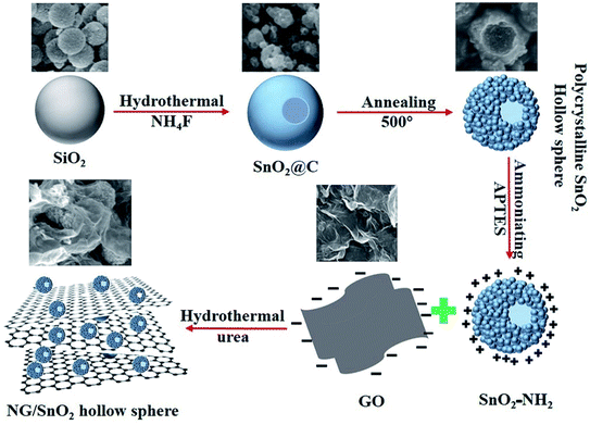
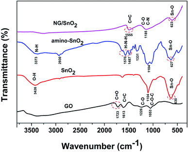
The formation mechanism of NG/SnO2 hollow spheres hybrids is schematically illustrated in Fig. 1. First, polycrystalline SnO2 hollow spheres were prepared by facile strategy of one-pot hydrothermal following a subsequent heat treatment with SiO2 act as sacrificial template. Second, amino-functional SnO2 hollow spheres were obtained via a post-grafting strategy with reflux. Third, amino-function SnO2 hollow spheres anchored on the GO sheets surface through electrostatic interaction and the NG/SnO2 hollow spheres hybrids were prepared by using a hydrothermal method with urea as the nitrogen source and reducing agent.Fig. 2 shows the FT-IR spectra of the samples at each stages of the experiments. The characteristic features of GO are the adsorption bands corresponding to the C![[double bond, length as m-dash]](https://www.rsc.org/images/entities/char_e001.gif) O stretching vibration at 1723 cm−1, C
O stretching vibration at 1723 cm−1, C![[double bond, length as m-dash]](https://www.rsc.org/images/entities/char_e001.gif) C deformation vibration at 1613 cm−1, C–OH stretching at 1226 cm−1 and C–O stretching at 1053 cm−1, indicating that abundant oxygen functional groups (–COOH, –OH) were introduced during the exfoliation of the graphene sheet.2 Compared the FT-IR spectrum of amino-function SnO2 hollow spheres with SnO2 hollow spheres, two new bonds were found at 3373 and 1570 cm−1 correspond to the coupling of N–H stretching vibration, suggesting that NH2 group have adhered to the surface of SnO2 hollow spheres.47 All samples except for GO show strong absorption at 500–700 cm−1 corresponding to characteristic vibration of O–Sn–O in the SnO2.48 For NG/SnO2 hollow spheres hybrids, the peaks at 1723, 1226 and 1503 cm−1 almost disappear, indicating that most oxygen function groups have been removed.2 There are three peaks at 1555, 1185 and 623 cm−1 can be assigned to the C
C deformation vibration at 1613 cm−1, C–OH stretching at 1226 cm−1 and C–O stretching at 1053 cm−1, indicating that abundant oxygen functional groups (–COOH, –OH) were introduced during the exfoliation of the graphene sheet.2 Compared the FT-IR spectrum of amino-function SnO2 hollow spheres with SnO2 hollow spheres, two new bonds were found at 3373 and 1570 cm−1 correspond to the coupling of N–H stretching vibration, suggesting that NH2 group have adhered to the surface of SnO2 hollow spheres.47 All samples except for GO show strong absorption at 500–700 cm−1 corresponding to characteristic vibration of O–Sn–O in the SnO2.48 For NG/SnO2 hollow spheres hybrids, the peaks at 1723, 1226 and 1503 cm−1 almost disappear, indicating that most oxygen function groups have been removed.2 There are three peaks at 1555, 1185 and 623 cm−1 can be assigned to the C![[double bond, length as m-dash]](https://www.rsc.org/images/entities/char_e001.gif) C, C–N(C–O) and Sn–O stretching vibration in NG/SnO2 hollow spheres hybrids, indicating that the SnO2 hollow spheres have been successful anchored on the NG surface.
C, C–N(C–O) and Sn–O stretching vibration in NG/SnO2 hollow spheres hybrids, indicating that the SnO2 hollow spheres have been successful anchored on the NG surface.
The XRD was utilized to investigate the phase structure of GO, NG, SnO2 hollow spheres and NG/SnO2 hollow spheres hybrids, as shown in Fig. 3(a). The GO shows a sharp peak at 10.9°, corresponding to its (001) crystal plane. The NG shows one significant diffraction peaks at 2θ = 25.3° attributed to the (002) reflection of graphitic carbon.49 The XRD pattern with the (110), (101), (200), (211), (222), (310), (112), and (321) planes confirmed the formation of SnO2 (JCPDS no. 21-1250). No apparent diffraction peak could be found at around 25° for NG/SnO2 hollow spheres hybrids, indicating that SnO2 hollow spheres have been decorated on the NG sheets surface, suppressing the stacking of graphene layers. Fig. 3(b) shows the Raman spectra of the samples, there are three characteristic peaks for SnO2 at 472, 632 and 775 cm−1 corresponding to Eg, A1g and B2g modes of crystalline SnO2, respectively.50 For GO, NG and NG/SnO2 hollow spheres hybrids, two apparent peaks centered at 1350 and 1590 cm−1 are attributed to the D bands associated with structure defects and G bands for the E2g vibration mode of sp2 carbon domains of carbon materials, respectively. The ratio of the intensity of D-band to G-band (ID/IG) is a measure of the degree of disorder in the graphene or GO.51 The D and G bands cannot be found in SnO2 hollow spheres, indicating that there is no carbon on the surface of SnO2 hollow spheres. There are three additional peaks corresponding to the SnO2 in the NG/SnO2 hollow spheres hybrids indicating that the SnO2 hollow spheres were efficiently deposited on the NG surface. The ID/IG increases from 0.97 for GO to 1.1 for NG/SnO2 hollow spheres hybrids, which suggest that more defects are formed during the SnO2 hollow spheres anchored on the NG surface and the reduction of GO.52 Both XRD and Raman measurement confirmed the successful integration of NG and SnO2 hollow spheres.
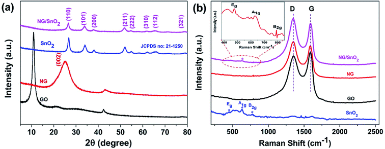 | ||
| Fig. 3 XRD patterns (a) and Raman spectra (b) of the GO, NG, SnO2 hollow spheres and NG/SnO2 hollow spheres hybrids. | ||
The morphologies and structures of GO, SnO2 hollow spheres and NG/SnO2 hollow spheres hybrids were further investigated by FESEM and TEM. As showed in Fig. 4(a), the aggregated GO powder shows a flaky crumple wrinkles.1 High resolution SEM image clearly shows that the SnO2 hollow spheres with an average diameter of 220 nm, as displayed in Fig. 4(b). From Fig. 4(c) and (d), it can be obviously seen that the SnO2 hollow spheres are uniformly anchored on the NG surface, forming sandwich-structure NG/SnO2 hollow spheres hybrids. Fig. 4(e) and (f) reveals the TEM images of NG/SnO2 hollow spheres hybrids, the NG is nearly transparent with lots of wrinkles on its surface and the hollow feature of SnO2 nanospheres is further confirmed by TEM image (Fig. 4(f)).1
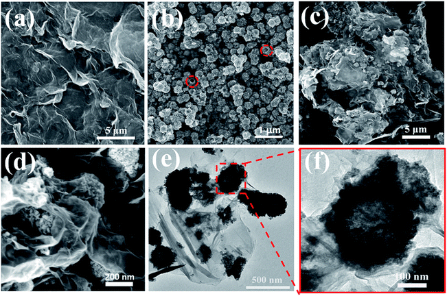 | ||
| Fig. 4 SEM images of GO (a), SnO2 hollow spheres (b), and NG/SnO2 hollow spheres hybrids (c) and (d), TEM imagine of NG/SnO2 hollow spheres hybrids (e) and (f). | ||
The surface chemical composition of the hybrids were characterized by XPS technology. Fig. 5(a) shows the survey scan XPS spectrum of NG/SnO2 hollow spheres hybrids which shows that the hybrids consist of Sn, O, C and N elements. The atomic percentage of N in the sample is about 3.44%, indicating that some C atom was replaced by N atom. From the high resolution spectrum of C 1s, the main peak at 284.9 eV corresponds to the graphite-like sp2 C (C![[double bond, length as m-dash]](https://www.rsc.org/images/entities/char_e001.gif) C), indicating most of the C atoms in the N-doped graphene are arranged in a conjugated honeycomb lattice. The peaks at 285.8 and 287.5 eV reflect different bonding structure of C–N bonds, N-sp2 C(–C
C), indicating most of the C atoms in the N-doped graphene are arranged in a conjugated honeycomb lattice. The peaks at 285.8 and 287.5 eV reflect different bonding structure of C–N bonds, N-sp2 C(–C![[double bond, length as m-dash]](https://www.rsc.org/images/entities/char_e001.gif) N) and N-sp3 C(–C–N) bonds, respectively, which originate from substitution of N atom, defects or the edge of the graphene sheets.53 Small peaks at 286.9 eV reflect different bonding structure of C–O bonds, indicating that there are also some oxygen functional groups on NG surface. Deconvolution of the high-resolution N 1s spectra shows distinct N-containing functional group coexisted, identified by their unique bonding states in the hybrids.54 The peaks locate at 398.6, 400 and 401.7 eV can be attributed to pyridinic-N, pyrrolic-N and graphitic-N respectively.54 Two symmetrical peaks at 487.4 eV and 495.8 eV are attributable to Sn 3d5/2 and Sn 3d3/2 are showed in Fig. 5(d), respectively, which is in good agreement with the energy splitting reported for SnO2.55
N) and N-sp3 C(–C–N) bonds, respectively, which originate from substitution of N atom, defects or the edge of the graphene sheets.53 Small peaks at 286.9 eV reflect different bonding structure of C–O bonds, indicating that there are also some oxygen functional groups on NG surface. Deconvolution of the high-resolution N 1s spectra shows distinct N-containing functional group coexisted, identified by their unique bonding states in the hybrids.54 The peaks locate at 398.6, 400 and 401.7 eV can be attributed to pyridinic-N, pyrrolic-N and graphitic-N respectively.54 Two symmetrical peaks at 487.4 eV and 495.8 eV are attributable to Sn 3d5/2 and Sn 3d3/2 are showed in Fig. 5(d), respectively, which is in good agreement with the energy splitting reported for SnO2.55
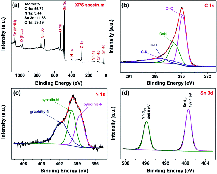 | ||
| Fig. 5 Survey scan (a), C 1s spectrum (b), N 1s spectrum (c) and Sn 3d spectrum (d) of NG/SnO2 hollow spheres hybrids. | ||
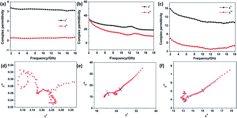
The frequency dependence of the complex permittivity and complex permeability for the SnO2 hollow spheres, NG and NG/SnO2 hollow spheres hybrids were are shown in Fig. 6. The real part (μ′) and imaginary part (μ′′) of the complex permeability of the samples are close to 1 and 0, respectively, due to the SnO2 and NG is nonmagnetic at room-temperature. The real part (ε′) and imaginary part (ε′′) for SnO2 hollow spheres are nearly constant within 2–18 GHz, with an inconspicuous undulation (ε′ ≈ 3.2 and ε′′ ≈ 0.28) as shown in Fig. 6(a). It can be observed that the ε′ and ε′′ for NG decrease gradually from 34.51 to 19.03 and 34.93 to 9.69, respectively, with a resonance peak at about 13.5 GHz. Fig. 6(c) shows the relative complex permittivity of NG/SnO2 hollow spheres hybrids. The ε′ values gradually decrease from 17.8 to 12.7 with the increase of the frequency and the ε′′ values are varied in the range of 3.78–7.5 over 2–18 GHz. The complex permittivity of NG/SnO2 hollow spheres hybrids is enhanced in the whole frequency range after the NG introduced compared with SnO2 hollow spheres, which should be ascribed to the increased electrical conductivity in the presence of NG. The obvious improvement of complex permittivity for NG/SnO2 hollow spheres hybrids is possibly due to relaxation polarization of the residual defect and groups of the NG surface which are generated by the reduction and N doping process of GO during the formation of NG/SnO2 hollow spheres hybrids.
On the basis of Debye relaxation, the relative complex permittivity can be expressed by the following equation:13,36
 | (1) |
Based on the generalized transmission line theory, the reflection loss (RL) curve of the absorber can be calculated based on the complex permittivity and permeability for the given absorber thickness and frequency by the following equation:56
 | (2) |
 | (3) |
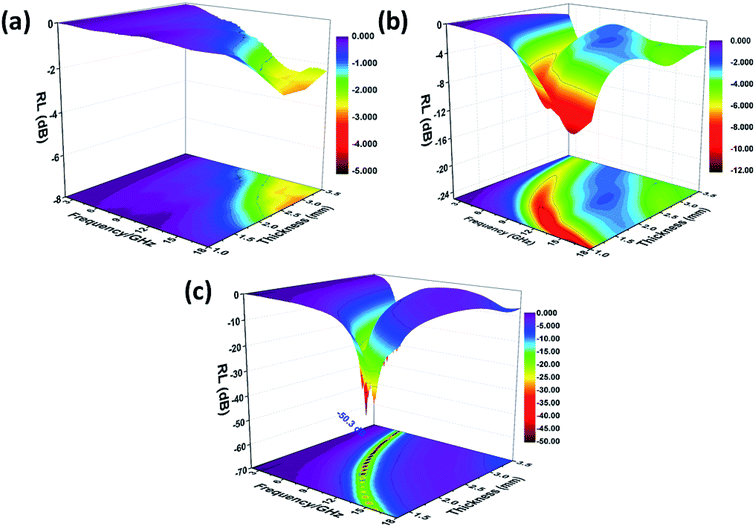 | ||
| Fig. 7 Three-dimensional RL values of SnO2 hollow spheres (a), NG (b) and NG/SnO2 hollow spheres hybrids (c). | ||
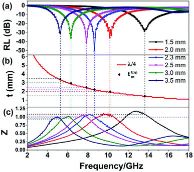
The quarter-wavelength cancellation model and zero reflection have been applied to analyze the enhanced microwave absorption. In the quarter-wavelength cancellation model, the relationship between the absorber thickness (tm) and the peak frequency (fm) can be described by the following equation:1,6,57,58
 | (4) |
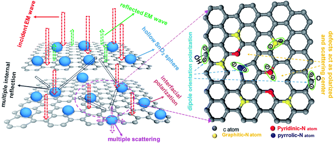
Fig. 9 shows the schematic illustration of EM absorption mechanisms in NG/SnO2 hollow spheres hybrids. The excellent microwave absorption properties of NG/SnO2 hollow spheres hybrids may be explained by the following facts. First, the residual defects and groups in NG which can act as polarized and scattering center introduce defect polarization relaxation and multiple scattering. Second, the introduction of SnO2 hollow spheres hybrids in NG plays an important role in increasing the microwave absorption properties, which not only bring into better impedance matching, but also strengthen interfacial polarization. Third, the hollow SnO2 spheres anchored on the RGO sheets can provide more sites for scattering of electromagnetic wave. Forth, there are multiple internal reflection between NG which produce further dissipate more electromagnetic energy. From the above discussion, it can be concluded that the enhanced microwave absorption performance of NG/SnO2 hollow spheres hybrids is ascribed to the dielectric loss, better impedance matching, multiple internal reflection and quarter-wavelength interference performance.
4. Conclusion
In summary, the NG/SnO2 hollow spheres hybrids, in which SnO2 hollow spheres with the average diameter of 220 nm anchored on NG sheet uniformly were synthesized. The NG/SnO2 hollow spheres hybrids exhibit a maximum RL value of −50.3 dB at 8.6 GHz with a matching thickness of only 2.3 mm. The effective absorption bandwidth (RL < −10 dB) is 4.2 GHz for NG/SnO2 hollow spheres hybrids with the thickness of only 1.3 mm. The enhancement of microwave absorption for NG/SnO2 hollow spheres hybrids is attributed to the synergistic effect of dielectric loss, better impedance matching, multiple internal reflection and quarter-wavelength interference performance. These results indicate that the NG/SnO2 hollow spheres hybrids are ideal candidate as microwave absorbing materials.Conflicts of interest
There are no conflicts of interest to declare.Acknowledgements
This work is supported by the grants from National Natural Science Foundation of China (Grant No. 61701185, 61801186 and 61605147) and China Postdoctoral Science Foundation funded project (Grant No. 2017M622444, 2018T110764 and 2018M630859).References
- J. Feng, F. Pu, Z. Li, X. Li, X. Hu and J. Bai, Carbon, 2016, 104, 214–225 CrossRef CAS.
- P. Liu, Y. Huang, J. Yan, Y. Yang and Y. Zhao, ACS Appl. Mater. Interfaces, 2016, 8(8), 5536–5546 CrossRef CAS PubMed.
- G. Tong, Y. Liu, T. Cui, Y. Li, Y. Zhao and J. Guan, Appl. Phys. Lett., 2016, 108(7), 072905 CrossRef.
- V. K. Tyagi and S. L. Lo, Renewable Sustainable Energy Rev., 2013, 18, 288–305 CrossRef CAS.
- B. Wen, M. Cao, M. Lu, W. Cao, H. Shi, J. Liu, X. X. Wang, H. B. Jin, X. Y. Feng, W. Z. Wang and J. Yuan, Adv. Mater., 2014, 26(21), 3484–3489 CrossRef CAS PubMed.
- X. Zhang, G. Ji, W. Liu, B. Quan, X. Liang, C. Shang, Y. Cheng and Y. Du, Nanoscale, 2015, 7(30), 12932–12942 RSC.
- R. C. Che, L. M. Peng, X. F. Duan, Q. Chen and X. L. Liang, Adv. Mater., 2004, 16, 401–405 CrossRef CAS.
- G. Tong, F. Liu, W. Wu, F. Du and J. Guan, J. Mater. Chem. A, 2014, 2(20), 7373–7382 RSC.
- Z. Liu, G. Bai, Y. Huang, Y. Ma, F. Du, F. Li, T. Y. Gao and Y. Chen, Carbon, 2007, 45(4), 821–827 CrossRef CAS.
- Y. Fan, H. Yang, M. Li and G. Zou, Mater. Chem. Phys., 2009, 115(2–3), 696–698 CrossRef CAS.
- C. Wang, X. Han, P. Xu, X. Zhang, Y. Du, S. Hu, J. Y. Wang and X. Wang, Appl. Phys. Lett., 2011, 98(7), 072906 CrossRef.
- P. Saini, V. Choudhary, B. P. Singh, R. B. Mathur and S. K. Dhawan, Mater. Chem. Phys., 2009, 113, 919–926 CrossRef CAS.
- H. Yu, T. Wang, B. Wen, M. Lu, Z. Xu, C. Zhu, Y. J. Chen, X. Y. Xue, C. W. Sun and M. Cao, J. Mater. Chem., 2012, 22(40), 21679–21685 RSC.
- K. Singh, A. Ohlan, V. H. Pham, R. Balasubramaniyan, S. Varshney, J. Jang, S. H. Hur, W. M. Choi, M. Kumar, S. K. Dhawan, B. S. Kong and J. S. Chung, Nanoscale, 2013, 5(6), 2411–2420 RSC.
- Y. Kang, Z. Chu, D. Zhang, G. Li, Z. Jiang, H. Cheng and X. Li, Carbon, 2013, 61, 200–208 CrossRef CAS.
- S. Yang, L. Zhi, K. Tang, X. Feng, J. Maier and K. Müllen, Adv. Funct. Mater., 2012, 22(17), 3634–3640 CrossRef CAS.
- F. Shahzad, S. Yu, P. Kumar, J. W. Lee, Y. H. Kim, S. M. Hong and C. M. Koo, Compos. Struct., 2015, 133, 1267–1275 CrossRef.
- L. Wang, Y. Huang and H. Huang, Mater. Lett., 2014, 124, 89–92 CrossRef CAS.
- H. Lv, G. Ji, X. Liang, H. Zhang and Y. Du, J. Mater. Chem. C, 2015, 3(19), 5056–5064 RSC.
- Y. Liu, X. X. Liu, R. Li, W. Wu and X. J. Wang, RSC Adv., 2015, 5(12), 8713–8720 RSC.
- W. Feng, Y. M. Wang, J. C. Chen, L. Wang, L. X. Guo, J. H. Ouyang, D. C. Jia and Y. Zhou, Carbon, 2016, 108, 52–60 CrossRef CAS.
- Y. Ren, C. Zhu, L. Qi, H. Gao and Y. Chen, RSC Adv., 2014, 4(41), 21510–21516 RSC.
- G. S. Wang, Y. Wu, Y. Z. Wei, X. J. Zhang, Y. Li, L. D. Li, B. Wen, P. G. Yin, L. Guo and M. S. Cao, ChemPlusChem, 2014, 79(3), 375–381 CrossRef CAS.
- H. Zhang, X. Tian, C. Wang, H. Luo, J. Hu, Y. Shen and A. Xie, Appl. Surf. Sci., 2014, 314, 228–232 CrossRef CAS.
- Y. Chen, Z. Lei, H. Wu, C. Zhu, P. Gao, Q. Y. Ouyang, L. H. Qi and W. Qin, Mater. Res. Bull., 2013, 48(9), 3362–3366 CrossRef CAS.
- T. Chen, F. Deng, J. Zhu, C. Chen, G. Sun, S. Ma and X. Yang, J. Mater. Chem., 2012, 22(30), 15190–15197 RSC.
- Y. L. Ren, C. L. Zhu, S. Zhang, C. Y. Li, Y. J. Chen, P. Gao, P. P. Yang and Q. Ouyang, Nanoscale, 2013, 5(24), 12296–12303 RSC.
- X. Li, J. Feng, Y. Du, J. Bai, H. Fan, H. Y. Peng and F. Li, J. Mater. Chem. A, 2015, 3(10), 5535–5546 RSC.
- Z. Yang, Z. Li, Y. Yang and Z. J. Xu, ACS Appl. Mater. Interfaces, 2014, 6(24), 21911–21915 CrossRef CAS PubMed.
- Y. Yong, Y. Yang, X. Wen and D. Jun, J. Appl. Phys., 2014, 115(17), 17A521 CrossRef.
- D. Zhu, J. Zhang, J. Song, H. Wang, Z. Yu, Y. Shen and A. Xie, Appl. Surf. Sci., 2013, 284, 855–861 CrossRef CAS.
- B. Zhao, X. Guo, Y. Zhou, T. Su, C. Ma and R. C. Zhang, CrystEngComm, 2017, 19(16), 2178–2186 RSC.
- M. Han, X. Yin, L. Kong, M. Li, W. Duan, L. Zhang and L. Cheng, J. Mater. Chem. A, 2014, 2(39), 16403–16409 RSC.
- M. Fu, Q. Jiao, Y. Zhao and H. Li, J. Mater. Chem. A, 2014, 2(3), 735–744 RSC.
- Y. Wang, Z. Luo and R. Hong, Mater. Lett., 2011, 65(21–22), 3241–3244 CrossRef CAS.
- B. Zhao, B. Fan, Y. Xu, G. Shao, X. Wang, W. Zhao and R. Zhang, ACS Appl. Mater. Interfaces, 2015, 7(47), 26217–26225 CrossRef CAS PubMed.
- Y. J. Chen, P. Gao, R. X. Wang, C. L. Zhu, L. J. Wang, M. S. Cao and H. B. Jin, J. Phys. Chem. C, 2009, 113(23), 10061–10064 CrossRef CAS.
- B. Zhao, G. Shao, B. Fan, W. Guo, Y. Chen and R. Zhang, Appl. Surf. Sci., 2015, 332, 112–120 CrossRef CAS.
- X. F. Zhang, X. L. Dong, H. Huang, B. Lv, J. P. Lei and C. J. Choi, J. Phys. D: Appl. Phys., 2007, 40(17), 5383 CrossRef CAS.
- H. Lv, Z. Yang, S. J. H. Ong, C. Wei, H. Liao, S. Xi, Y. Du, G. Ji and Z. J. Xu, Adv. Funct. Mater., 2019, 1900163 CrossRef.
- H. Lv, Z. Yang, P. L. Wang, G. Ji, J. Song, L. Zheng, H. Zeng and Z. J. Xu, Adv. Mater., 2018, 30(15), 1706343 CrossRef PubMed.
- F. Li, J. Song, H. Yang, S. Gan, Q. Zhang, D. Han, A. Ivaska and L. Niu, Nanotechnology, 2009, 20(45), 455602 CrossRef PubMed.
- J. Liang, W. Wei, D. Zhong, Q. Yang, L. Li and L. Guo, ACS Appl. Mater. Interfaces, 2012, 4(1), 454–459 CrossRef CAS PubMed.
- W. S. Hummers Jr and R. E. Offeman, Preparation of graphitic oxide, J. Am. Chem. Soc., 1958, 80(6), 1339 CrossRef.
- Q. Tian, Y. Tian, Z. Zhang, L. Yang and S. I. Hirano, J. Power Sources, 2015, 280, 397–405 CrossRef CAS.
- Q. Tian, Z. Zhang, L. Yang and S. I. Hirano, J. Power Sources, 2015, 279, 528–532 CrossRef CAS.
- A. Pawlak and M. Mucha, Thermochim. Acta, 2003, 396(1–2), 153–166 CrossRef CAS.
- M. Aziz, S. S. Abbas, W. R. W. Baharom and W. Z. W. Mahmud, Mater. Lett., 2012, 74, 62–64 CrossRef CAS.
- Y. Chen, A. Zhang, L. Ding, Y. Liu and H. Lu, Composites, Part B, 2017, 108, 386–392 CrossRef CAS.
- R. S. Katiyar, P. Dawson, M. M. Hargreave and G. R. Wilkinson, J. Phys. C: Solid State Phys., 1971, 4(15), 2421 CrossRef CAS.
- Y. Gao, X. Pu, D. Zhang, G. Ding, X. Shao and J. Ma, Carbon, 2012, 50(11), 4093–4101 CrossRef CAS.
- Y. Li, X. Lv, J. Lu and J. Li, J. Phys. Chem. C, 2010, 114(49), 21770–21774 CrossRef CAS.
- D. Wei, Y. Liu, Y. Wang, H. Zhang, L. Huang and G. Yu, Nano Lett., 2009, 9(5), 1752–1758 CrossRef CAS PubMed.
- D. Deng, X. Pan, L. Yu, Y. Cui, Y. Jiang, J. Qi, W. Li, Q. Fu, Q. Ma, G. Sun and X. Bao, Chem. Mater., 2011, 23(5), 1188–1193 CrossRef CAS.
- X. Wang, X. Cao, L. Bourgeois, H. Guan, S. Chen, Y. Zhong, D. Tang, H. Li, T. Zhai, L. Li and Y. Bando, Adv. Funct. Mater., 2012, 22(13), 2682–2690 CrossRef CAS.
- P. Bhattacharya, S. Dhibar, M. K. Kundu, G. Hatui and C. K. Das, Mater. Res. Bull., 2015, 66, 200–212 CrossRef CAS.
- X. Zhang, G. Ji, W. Liu, X. Zhang, Q. Gao, Y. Li and Y. Du, J. Mater. Chem. C, 2016, 4(9), 1860–1870 RSC.
- B. Quan, X. Liang, G. Ji, J. Lv, S. Dai, G. Xu and Y. Du, Carbon, 2018, 129, 310–320 CrossRef CAS.
| This journal is © The Royal Society of Chemistry 2019 |

