 Open Access Article
A rational design of the coupling mechanism of physical adsorption and chemical charge effect for high-performance lithium–sulfur batteries†
Guilin Fenga,
Xiaohong Liua,
Yasai Wanga,
Zhenguo Wu a,
Chen Wua,
Rong Lia,
Yanxiao Chen
 *a,
Xiaodong Guoa,
Benhe Zhonga and
Jianshu Lib
aSchool of Chemical Engineering, Sichuan University, Chengdu 610065, P. R. China. E-mail: yxchen888@163.com; Fax: +86-28-85406702; Tel: +86-28-85406702
bCollege of Polymer Science and Engineering, State Kay Laboratory of Polymer Materials Engineering, Sichuan University, Chengdu 610065, People's Republic of China
First published on 24th April 2019
Abstract
Lithium sulfur batteries are considered as potential energy storage systems for electrical devices owing to their high energy density, low cost, and environmental friendliness. However, the hasty capacity fading originating from the solution and migration of polysulfides is the major obstacle for their industrial application. The polysulfide adsorption and repulsion effect achieved by adding an extra coating layer on the side of the cathode and separator have been separately proved to be effective in mitigating the shuttle effect. Herein, a cooperative coated separator, which employs a hybrid carbon matrix as the coated material, including an appropriate ratio of N-doped activated conductive carbon and commercial acetylene black, and sulfonated polystyrene as the binder, is established to prevent the migration of polysulfides and serves as a secondary current collector to reutilize the active materials for high-performance lithium sulfur batteries. The research results showed that the coated separator with 50 wt% N-doped activated conductive carbon as the coating material and sulfonated polystyrene as the binder showed highlighted cycle performance, and 731 mA h g−1 was maintained after 150 cycles at 800 mA g−1(the capacity retention was 86.0%). The superior performance may be because the coated separator can efficiently restrain the polysulfides by physical and chemical effects and also reject the polysulfides by the anion electrostatic effect. In summary, this study provides a new cooperative way to address the shuttle effect and promotes the development of lithium sulfur batteries.
1. Introduction
The rapid growth of electric automobiles and portable electronic devices propels higher performance demands on batteries. Hence, it is extremely urgent to exploit a novel green energy storage lithium-ion battery with high specific energy.1–4 Among the next alternatives of energy storage systems, lithium sulfur (Li–S) batteries are regarded as one of the most potential batteries due to their high theoretical specific capacity (1675 mA h g−1) and high energy densities (2600 W h kg−1), which far exceeds those of the traditional lithium-ion batteries.5–9 Furthermore, the intrinsic characteristics of the sulfur cathode, such as environment benignity, low cost, and abundant resources, further push forward the progress of Li–S batteries.10–13 However, their practical commercial applications are still impeded by the sharp capacity degradation, severe volume change, limited coulombic efficiency, transfer of high-order lithium polysulfides (LPSs) into low-order LPSs and the migration of low-order LPSs between the cathode and anode creating the “shuttle effect”.14–19To address the abovementioned challenges, significant efforts have been made, and various strategies have been investigated. The general strategy is to anchor sulfur in various carbon materials with fixed special construction and pore sizes.20–22 Although these strategies could effectively trap LPSs in the cathode and strengthen the electrochemical performance of Li–S batteries, the complex designed structures and the high-priced treatment techniques are inapplicable in large-scale manufacturing processes. Based on the previous studies, a series of functional separators with the electrostatic effect,23,24 physical constraint effect,25,26 and chemical adsorption effect14,27,28 have been designed for simplification. For instance, a particular sulfonated acetylene black (AB–SO3−)-coated separator with electronegative coating layers could effectively enhance the performance of Li–S batteries, owing to the electrostatic repulsion between the AB–SO3− and LPSs.29 Zhu et al.30 prepared a carbon-based aerogel to modify the separator, which could deliver a reversible discharge capacity, due to the screen size effect of the coated layer. Quan-Hong Yang et al. designed a tight coating composed of Li4Ti5O12 and graphene on the separator, which could develop an excellent cycle lifetime in Li–S batteries (697 mA h g−1 after 500 cycles at 1C, the capacity retention was 85.7%), as a result of the chemical adsorption effect of Li4Ti5O12 on LPSs.31 Moreover, carbon matrices doped with heteroatoms have been proved to have a large potential for the adsorption of LPSs.32,33 Although these modified methods from a single angle have shown improved performances, settling the shuttle effect of Li–S batteries still remains a big challenge. Recently, the application of polystyrene sulfonate@HKUST-1 has been demonstrated to increase the capacity, due to the facilitation of lithium ion transport and the electrostatic effect. Besides, the application of N, P element in Li–S batteries has been further proved its strong chemical adsorption to polysulfides, improving rate and cycling performance.1,34,35
Herein, a novel coated separator was devised, as shown in Fig. 1, which employed the sulfonated polystyrene (SPS) as the binder and appropriate ratio of N-doped activated conductive carbon (NACC) and acetylene black (AB) as the coated materials. The coated separator could effectively mitigate the shuttle effect via the repulsive effect and chemical effect of N-doped carbon. Compared with ordinary conductive materials, N-doped carbon could act as a good anchor of LPSs. Moreover, NACC rooted from biomass tea, is low-cost and easily prepared. Besides, SPS has a large repulsive effect due to the functional group –SO3H. To further explore the effect of SPS-N-doped carbon (S-NACC) in Li–S batteries, the AB-coated separator with polyvinylidene fluoride (P-AB) as the binder was introduced for comparison; moreover, the S-NACC-coated layer could be used as a screen for the diffusion of LPSs due to the cooperated effect of –SO3H and N-doped carbon, which could restrict the soluble LPS species by a physical region and also mitigate the shuttle of soluble LPSs by anion electrostatic effect, leading to a superior rate performance (710 mA h g−1 at 1600 mA g−1) and stable cycle stability after 150 cycles (retained 86.0% at 800 mA g−1).
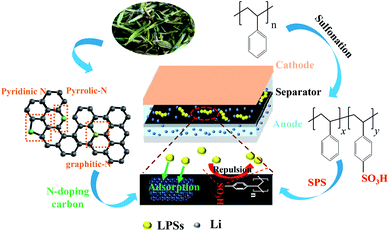 | ||
| Fig. 1 Working diagrams of S-NACC-coated separator and details of the carbonization of tea and the sulfonation of polystyrene. | ||
2. Experimental
2.1 Synthesizing materials and coated separator
![[thin space (1/6-em)]](https://www.rsc.org/images/entities/char_2009.gif) :
:![[thin space (1/6-em)]](https://www.rsc.org/images/entities/char_2009.gif) y
y![[thin space (1/6-em)]](https://www.rsc.org/images/entities/char_2009.gif) :
:![[thin space (1/6-em)]](https://www.rsc.org/images/entities/char_2009.gif) 10%) using N-methyl-e-pyrrolidinone (NMP) as the solvent. Then, using an automatic coating machine, the slurry was coated on one side of the pristine separator, and the coated separator was dried at 55 °C in a vacuum oven for 14 h after being placed overnight at room temperature. As the control, the AB-P-coated separator with the binder polyvinylidene fluoride (PVDF) was treated by the same process. PVDF Kynar 740, was bought from the Shanghai East Fluorine Chemical Technology Co., Ltd.
10%) using N-methyl-e-pyrrolidinone (NMP) as the solvent. Then, using an automatic coating machine, the slurry was coated on one side of the pristine separator, and the coated separator was dried at 55 °C in a vacuum oven for 14 h after being placed overnight at room temperature. As the control, the AB-P-coated separator with the binder polyvinylidene fluoride (PVDF) was treated by the same process. PVDF Kynar 740, was bought from the Shanghai East Fluorine Chemical Technology Co., Ltd.2.2 Preparing sulfur/carbon cathode and assembling cells
Sulfur was bought from the Chengdu Kelong chemical reagent factory and directly used without other treatments. Ketjen black (KB) powder was purchased from the Shandong Coase new energy co. LTD. The sulfur/carbon (S/C) cathode powder was prepared by mechanical mixing and following the solid state method. The sulfur powder and KB were mixed at a weight ratio of 4![[thin space (1/6-em)]](https://www.rsc.org/images/entities/char_2009.gif) :
:![[thin space (1/6-em)]](https://www.rsc.org/images/entities/char_2009.gif) 1, and then subjected to ball milling for 40 min. To acquire the experimental S/C materials, the mixture was heated at 155 °C for 12 h in a tube furnace with Ar atmosphere. And then the heated product as active material (70 wt%) mixed amount of AB (20 wt%) with PVDF (10 wt%) finally makes up the composite of slurry dispersed in NMP. Then, the slurry was coated on an aluminum foil and dried in a vacuum oven for 12 h at 80 °C. The electrode with a diameter of 14 mm was gathered by cutting the obtained piece; the average weight of the sulfur-KB, acetylene black and PVDF coated on the Al foil was 1.3 mg cm−2.
1, and then subjected to ball milling for 40 min. To acquire the experimental S/C materials, the mixture was heated at 155 °C for 12 h in a tube furnace with Ar atmosphere. And then the heated product as active material (70 wt%) mixed amount of AB (20 wt%) with PVDF (10 wt%) finally makes up the composite of slurry dispersed in NMP. Then, the slurry was coated on an aluminum foil and dried in a vacuum oven for 12 h at 80 °C. The electrode with a diameter of 14 mm was gathered by cutting the obtained piece; the average weight of the sulfur-KB, acetylene black and PVDF coated on the Al foil was 1.3 mg cm−2.
The batteries were assembled using different separators in a glove box, filled with Ar atmosphere, and the content of H2O and O2 was 0.1 ppm. Moreover, 0.65 M lithium bis(trifluoromethanesulfonyl)imide (LiTFSI) solution in 1,2-dimethoxy ethane (DME)/1,3-dioxolane (DOL) (1![[thin space (1/6-em)]](https://www.rsc.org/images/entities/char_2009.gif) :
:![[thin space (1/6-em)]](https://www.rsc.org/images/entities/char_2009.gif) 1, v/v) with 0.1 M LiNO3 additive was used as the electrolyte, and the counter electrode was lithium metal. The addition of the electrolyte was about 30 μL in every cell.
1, v/v) with 0.1 M LiNO3 additive was used as the electrolyte, and the counter electrode was lithium metal. The addition of the electrolyte was about 30 μL in every cell.
2.3 Characterization
The surface morphologies of NACC and the separators were detected by means of field emission scanning electron microscopy (SEM, SPA400 Seiko Instruments). Atomic force microscope (AFM) was used to study the surface morphology of the modified separators. Fourier transform infrared spectroscopy (FT-IR) using the KBr method in the wave number range of 400–4000 cm−1 was carried out on a Nicolet iS50 to observe the SO32− of SPS. Thermogravimetric analysis (TGA, TA Instruments, Q600) was used to determine the content of S with a heat speed of 10 °C min−1 from 25 to 500 °C. X-ray photoelectron spectroscopy (XPS) was used to analyze the effect of the coated separator. Raman spectra were gathered with a HORIBA HR800 using 532 nm laser to observe the property of NACC. The 1H NMR spectra were obtained on an Avance III 400 (Bruker) to determine the DS of the SPS, which employed a solution of the SPS polymer in deuterated dimethyl sulfoxide (DMSO-d6) and tetramethylsilane (TMS) was the internal standard. The energy dispersive X-ray spectrometer (EDX) image was used for morphology analysis. The Brunauer–Emmett–Teller (BET) surface area was obtained from the nitrogen adsorption–desorption isotherms.The electrical impedance spectroscopy (EIS) tests of the batteries were conducted using the electrochemical workstation (Germany, ZenniumIM6). The assembled batteries were galvanostatically measured using the LAND-CT2001A battery testing system in the potential window of 1.0–2.8 V to observe the electrochemical stability of Li–S batteries.
3. Results and discussion
The reaction formula of SPS is depicted in Fig. 2a, which details the construction and aromatic proton numbering of SPS. It can be seen that –H on the counterpoint is likely to be replaced by –SO3H, because of the electronic effect of polystyrene. The 1H NMR spectra of SPS in DMSO-d6 reflect the 1H NMR spectra of the SPS to confirm the degree of sulfonation (DS = y/(x + y)) of SPS. According to the method described in the literature,37 the proportional peak area of the distinct peak (2′, 2′) at 7.4 ppm denoted as (A2′, 2′) and the integrated peak area of the signals at 7.1 ppm corresponding to all the other aromatic hydrogens denoted as (A1′, 1′) are in accord with the following equation:
 | (1) |
![[double bond, length as m-dash]](https://www.rsc.org/images/entities/char_e001.gif) O bond, respectively, indicating the success of the sulfonation reaction.
O bond, respectively, indicating the success of the sulfonation reaction.
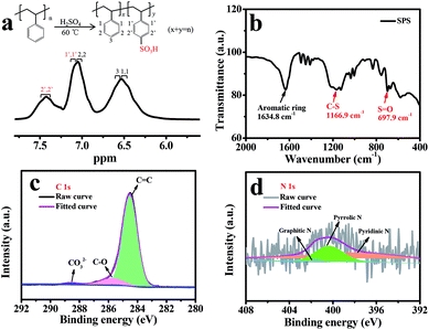 | ||
| Fig. 2 (a) Reaction formula of SPS and 1H NMR spectra of the prepared SPS in DMSO-d6; (b) the FT-IR spectrum of SPS; (c) XPS survey of C 1s spectra and (d) N 1s spectra for the prepared NACC. | ||
The TGA result of the S/C composite powder is shown in Fig. S2.† The sudden weight loss comes from the sublimation of sulfur when the temperature changes to 360 °C, indicating that the sulfur content is about 79.6 wt%, which is in agreement with our designed value (80%). As shown in Fig. S3,† NACC displays an irregular morphology after activation. To explore the pore structure and specific surface area, the nitrogen gas adsorption–desorption isotherms and the distributed pore size of NACC were studied, as displayed in Fig. S4a and b.† The calculated specific surface area of NACC is 484.2 m2 g−1 and the cumulative pore diameter is at 3.9 nm, which would be helpful for enhancing the contact area of the electrolyte and providing transport channels for lithium ions.30,38 Raman spectroscopy was applied for revealing the structural information and property of the carbon materials, as shown in Fig. S5.† The two peaks at 1336.3 and 1599.1 cm−1 correspond to the D bond and G bond, respectively. The former bond is indexed to the existence of amorphous carbon or deficient graphitized carbon, and the latter band is related to the tangential vibration of the sp2-bonded carbon atoms in the crystallographic graphite structure.34,39 In addition, it could be calculated that the peak height ratio of ID/IG is 1.01, which shows a favorable graphitization degree for NACC. The graphitic structure developed in NACC is beneficial for the electronic conductivity.
The surface valances state of N and C element in NACC were further explored by XPS. The fitted C 1s spectra (Fig. 2c) of NACC exhibit three peaks at about 284.5, 285.8 and 288.3 eV, corresponding to the three categories C![[double bond, length as m-dash]](https://www.rsc.org/images/entities/char_e001.gif) C, C–O and CO32−,40,41 respectively. The high content of C
C, C–O and CO32−,40,41 respectively. The high content of C![[double bond, length as m-dash]](https://www.rsc.org/images/entities/char_e001.gif) C bond is consistent with the results of the Raman spectra. The N 1s spectra are shown in Fig. 2d, which reveal the presence of the three nitrogen species, graphitic-N (401.2 eV), pyrrolic-N (400.9 eV) and pyridinic-N (398.1 eV), respectively.34,42 The three combined ways of N atom and carbon atom would be helpful for confining the soluble LPSs.
C bond is consistent with the results of the Raman spectra. The N 1s spectra are shown in Fig. 2d, which reveal the presence of the three nitrogen species, graphitic-N (401.2 eV), pyrrolic-N (400.9 eV) and pyridinic-N (398.1 eV), respectively.34,42 The three combined ways of N atom and carbon atom would be helpful for confining the soluble LPSs.
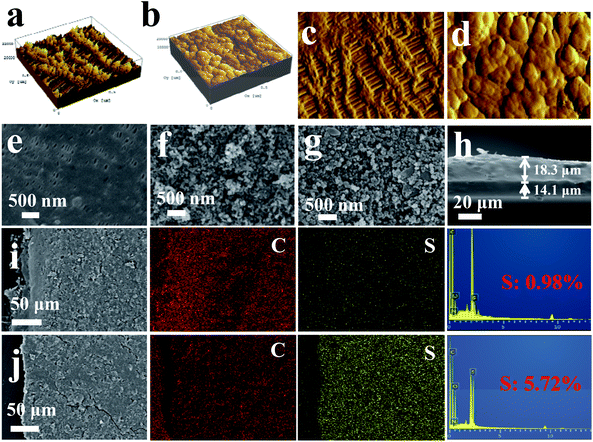
To further study the surface morphology of the modified and initial separators, the atomic force microscope (AFM) technique was applied. Fig. 3a and b shows the 3D topographic AFM images of the different separators; it can be seen that the surface appearance clearly changes after coating, and the coating separator shows a relatively smooth and tight surface. The 2D morphological image of the pristine separator shows a series of pores in micron ranges, but the coated separator (Fig. 3c) shows a close-grained surface, which may be beneficial for blocking LPSs through the separator. The SEM images of the coated separators show three-dimensional porous networks with numerous particle stacking, which could effectively restrict LPSs by a physical region. Nevertheless, the pristine separator has many pores, which are not beneficial to inhibit the migration of LPSs. The result is in keeping with the AFM results. Furthermore, the Raman result of the S-NACC-coated separator is shown in Fig. S5b,† which is similar with the Raman result of NACC, since the main composites of the coated separator are carbon materials. Fig. 3h is the section image of the S-NACC-50%-coated separator; it can be seen that the thicknesses of the Celgard and the coated layer are around 14.1 and 18.3 μm, respectively.
In order to examine the trapped effect in the coating layer, the SEM and EDX results of the S-NACC-50%-coated separator are shown in Fig. 3i and j. It can be seen that there is no obvious sulfur signal in the SEM image before cycling. However, after cycling there is an apparent sulfur signal in the coated layer, which manifests that the S-NACC-50%-coated separator could effectively restrict the dissolved LPSs by the construction of a barrier region. It's worth mentioning that there is about 0.98% sulfur in the coated separator before cycling, which could be associated with the addition of SPS (10%). This result is in keeping with the 1H NMR test of SPS.
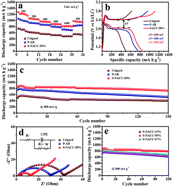
The rate performance of the different separators is depicted in Fig. 4a, and all capacities are on account of the weight of the absolute sulfur material. Among them, from 100 to 1600 mA g−1, the S-NACC-50%-coated separator delivers higher reversible discharge capacities of ∼1200 and ∼820 mA h g−1, respectively, and the discharge capacities of the P-AB-coated separator are lower, ∼1000 and ∼710 mA h g−1, respectively. In contrast, the conventional separator only maintains the capacities of ∼700 and ∼490 mA h g−1, respectively. The rate capabilities of the three samples obviously indicate that the S-NACC-50%-coated separator is better than the P-AB-coated separator and the conventional one in Li–S batteries. What's more, 960 mA h g−1 could be maintained when the current density changed to 200 mA g−1 because the NACC-50%-coated separator could effectively mitigate the shuttle effect of LPSs in Li–S batteries. The initial charge–discharge curves of the different separators at 800 mA g−1are shown in Fig. 4b. The voltage curves of all the batteries express a similar voltage platform during the discharge–charge processes, which consists of two discharging plateaus, a short higher plateau at 2.30 V and a long lower plateau at 2.10 V. Additionally, only a long plateau during the charging process. The two plateaus during the discharging–charging processes correspond to the two-step sulfur redox reactions. Specially, the former plateau at 2.30 V shows that the sulfur obtained electrons and yielded long-chain LPSs (Li2Sx, 4 < x < 8), and the latter plateau at 2.10 V is associated with the further transformation of the long-chain LPSs into lower-order Li2S2 and Li2S. The voltage gaps between the charge and discharge plateaus of the pristine sample, P-AB sample and S-NACC-50% sample are gradually decreasing, indicating that the S-NACC-50% sample possesses the lowest polarization and better dynamitic performance. The corresponding dQ/dV results of the three different separators are shown in Fig. S6,† which are in agreement with the results of the rate capacities.
Fig. 4c presents the cycling performance of the three samples at 800 mA g−1. The initial discharge capacities of the S-NACC-50%, P-AB and conventional separator are 847.5, 760.3 and 543.4 mA h g−1, respectively. In addition, the S-NACC-50% sample maintains a capacity of 731.3 mA h g−1 after 150 cycles, and the capacity retention is 86.0%. Nevertheless, the capacity of the P-AB sample is 529.9 mA h g−1, corresponding to a capacity retention of 69.7%. The capacity of the Celgard sample is 404.7 mA h g−1 (the capacity retention is 74.4%). It is noticeable that the Li–S cells using the S-NACC-50%-modified separator deliver a more stable cycling performance than the P-AB-coated and pristine Celgard; the low capacity attenuation may be attributed to the LPSs prevented by the repulsive effect and the effect of the functional surface groups. The EIS measurement results of fresh batteries with the three separators are shown in Fig. 4d. It is clearly seen that the three samples display the representative semicircles at high frequencies and a short oblique line in the low-frequency area. The high-frequency semicircle represents the charge-transfer resistance (Rct) of the sulfur cathode, and the low-frequency sloping lines reflect the lithium-ion diffusion resistance within the electrodes.43 From correlative equivalent circuit models, the cell with the S-NACC-50%-coated separator showed a Rct value of 9.9 Ω, which is lower than that of the cell with the P-AB-coated separator (26.4 Ω) and conventional separator (38.0 Ω). It could be guessed that the charge-transfer resistance would be reduced by the addition of SPS and NACC, which could decrease the kinetics impedance, and the result is corresponding to the cycle performance tests.
The self-discharge behaviors are mainly impacted by the shuttle effect in Li–S batteries, which has a close connection with the industrial application.44 To evaluate the performance of the three samples, the open circuit potential of Li–S batteries was recorded with the change of time, which is shown in Fig. S7.† The open voltage of Li–S batteries with the pristine separator rapidly decayed to 2.30 V while the open voltage of those with the P-AB- and S-NACC-50%-coated separators were about 2.32 V, within 6 h. This indicted that high-order LPSs turned into low-order LPSs during the self-discharging measurement. As for the coated separator, the capacity retention is higher than that for an uncoated separator.
To better understand the effect of the addition of NACC, different ratios of NACC additions in the coated separator were compared. The cells with S-NACC-33% (the mass ratio of NACC and AB is 1![[thin space (1/6-em)]](https://www.rsc.org/images/entities/char_2009.gif) :
:![[thin space (1/6-em)]](https://www.rsc.org/images/entities/char_2009.gif) 2), S-NACC-50% and S-NACC-67% (the mass ratio of NACC and AB is 2
2), S-NACC-50% and S-NACC-67% (the mass ratio of NACC and AB is 2![[thin space (1/6-em)]](https://www.rsc.org/images/entities/char_2009.gif) :
:![[thin space (1/6-em)]](https://www.rsc.org/images/entities/char_2009.gif) 1) were studied. Research shows that the additions of NACC have an impact on the performance of Li–S batteries. Fig. S8† shows the rate performance of the three samples. It could be seen that the S-NACC-50% presented a better performance than the S-NACC-33% and S-NACC-67% at various rates, especially at 1600 mA g−1. Furthermore, Fig. 4e presents the cycling performances of the three samples at 800 mA g−1. The initial discharge capacities are 847, 775 and 749 mA h g−1, respectively. After 100 cycles, the S-NACC-50% delivers a capacity of 794 mA h g−1 and the capacity retention is 93.7%. The rate and cycle performances for different ratios of NACC additions demonstrate that S-NACC-50% may be more beneficial to remit the shuttle effect; the chemical and physical effect are influenced by the proper ratio used. Because of the irregular morphology, NACC may not be beneficial to trap LPSs, but the character of including N would show good chemical effect on LPSs. So the use of a proper ratio of NACC in the coated separator is feasible. To further research the cycle performance of S-NACC-50%, the cycle performance at 1600 mA g−1 after 100 cycles was studied, as presented in Fig. S9;† the acquired capacity was 620 mA h g−1, corresponding to a capacity retention of 88.1%.
1) were studied. Research shows that the additions of NACC have an impact on the performance of Li–S batteries. Fig. S8† shows the rate performance of the three samples. It could be seen that the S-NACC-50% presented a better performance than the S-NACC-33% and S-NACC-67% at various rates, especially at 1600 mA g−1. Furthermore, Fig. 4e presents the cycling performances of the three samples at 800 mA g−1. The initial discharge capacities are 847, 775 and 749 mA h g−1, respectively. After 100 cycles, the S-NACC-50% delivers a capacity of 794 mA h g−1 and the capacity retention is 93.7%. The rate and cycle performances for different ratios of NACC additions demonstrate that S-NACC-50% may be more beneficial to remit the shuttle effect; the chemical and physical effect are influenced by the proper ratio used. Because of the irregular morphology, NACC may not be beneficial to trap LPSs, but the character of including N would show good chemical effect on LPSs. So the use of a proper ratio of NACC in the coated separator is feasible. To further research the cycle performance of S-NACC-50%, the cycle performance at 1600 mA g−1 after 100 cycles was studied, as presented in Fig. S9;† the acquired capacity was 620 mA h g−1, corresponding to a capacity retention of 88.1%.
To further explore the function mechanism of the S-NACC-50%-coated separator on LPSs, the XPS spectra of P-AB- and S-NACC-50%-coated separator were obtained, as shown in Fig. 5. It can be seen that there are mainly two N species, graphitic-N (401.1 eV) and pyridinic-N (398.4 eV), in Fig. 5a.34,45 Particularly, the content of graphitic-N in the S-NACC-50% sample is higher that in the P-AB sample, which may be due to the introduction of NACC which innately consists of natural nitrogen, and the results are in keeping with the XPS analysis of NACC. As shown in Fig. 5b, for the two samples, the peaks of S0 (164.2 eV), S–O (165.7 eV), SO32− (167.5 eV), C–S (169.5 eV) and sulfate (170.3 eV)46 are detected; the detected sulfur signals after cycling indicate that the active materials are effectively trapped in the coated separator. Paying attention to the P-AB-coated separator, the peak of S−1 (162.6 eV) shows a discharge product of S cathode. However, the peak of S−1 couldn't be detected in the S-NACC-50%-coated separator and the content of S0 is lesser than that in the P-AB-coated separator, which may be associated with the repulsive effect of SPS, resulting in less LPSs being deposited on the coated separator. This result demonstrates the strong repulsive effect of SPS for LPSs.
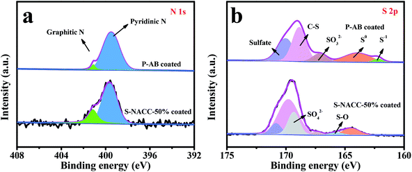 | ||
| Fig. 5 XPS spectra of (a) N 1s, and (b) S 2p for P-AB-coated separator and S-NACC-50%-coated separator after cycling. | ||
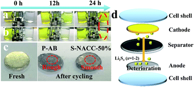
In order to visually verify the effect of the two types of coated separators, polysulfide diffusion experiments were conducted, as shown in Fig. 6a and b. According to previous studies,47 the polysulfide (Li2S6) solution was prepared for this experiment. Comparing the change of color after 24 h, it could be seen that the S-NACC-50%-coated separator shows a better rejection to polysulfides than the P-AB-coated separator. This implies that the S-NACC-50%-coated separator could effectively reject the LPSs and mitigate the shuttle effect. Fig. 6c presents the surfaces of Li anode;48 it can be seen that the surface is smooth for fresh Li anode. However, the surfaces have changed after cycling. For the P-AB-coated separator, the surface is rougher than for the S-NACC-50%-coated separator, indicating that more LPSs move to the Li anode and react with Li anode; the process of deterioration is shown in Fig. 6d.
4. Conclusion
In summary, a S-NACC-50%-coated separator was designed by a combination of the physical effect, chemical effect and repulsive barrier to mitigate the shuttle effect of LPSs in Li–S batteries. The enhancement of Li–S batteries could be strongly related with the application of NACC and SPS. For one thing, the conductive carbon (NACC and AB)-coated separator could trap LPSs by the physical and chemical effect and reutilize the trapped LPSs as the upper current collector. For another, the introduction of SPS could reject the LPSs by the repulsive effect, due to the existence of –SO3H in SPS. The S-NACC-50%-coated separator could obtain a discharge capacity of 731 mA h g−1 after 150 cycles at 800 mA g−1. Hence, the design of the S-NACC-50%-coated separator could be regarded as an effective route to improve the electrochemical performance of Li–S batteries and promote their practical application.Conflicts of interest
There are no conflicts of interest.Acknowledgements
This work was financially supported by the National Natural Science funds (21534008).References
- Y. Guo, M. Sun, H. Liang, W. Ying, X. Zeng, Y. Ying, S. Zhou, C. Liang, Z. Lin and X. Peng, ACS Appl. Mater. Interfaces, 2018, 10, 30451–30459 CrossRef CAS PubMed.
- W. Chen, T. Lei, W. Lv, Y. Hu, Y. Yan, Y. Jiao, W. He, Z. Li, C. Yan and J. Xiong, Adv. Mater., 2018, 1804084 CrossRef PubMed.
- R. Fang, K. Chen, L. Yin, Z. Sun, F. Li and H. M. Cheng, Adv. Mater., 2018, 1800863 Search PubMed.
- Z. Gao, Y. Schwab, Y. Zhang, N. Song and X. Li, Adv. Funct. Mater., 2018, 28, 1800563 CrossRef.
- X. Liu, T. Qian, J. Liu, J. Tian, L. Zhang and C. Yan, Small, 2018, 14, 1801536 CrossRef PubMed.
- Q. Liu, J. Zhang, S. A. He, R. Zou, C. Xu, Z. Cui, X. Huang, G. Guan, W. Zhang, K. Xu and J. Hu, Small, 2018, 14, 1703816 CrossRef PubMed.
- Y. Zheng, H. Fan, H. Li, C. Fan, H. Yuan, Z. Yang, K. Huang, W. Li and J. Zhang, Chemistry, 2018, 24, 13582–13588 CrossRef CAS PubMed.
- J. He, Y. Chen, W. Lv, K. Wen, C. Xu, W. Zhang, Y. Li, W. Qin and W. He, ACS Nano, 2016, 10, 10981–10987 CrossRef CAS PubMed.
- J. He, Y. Chen, W. Lv, K. Wen, P. Li, F. Qi, Z. Wang, W. Zhang, Y. Li, W. Qin and W. He, J. Power Sources, 2016, 327, 474–480 CrossRef CAS.
- Y. He, S. Bai, Z. Chang, Q. Li, Y. Qiao and H. Zhou, J. Mater. Chem. A, 2018, 6, 9032–9040 RSC.
- G. Feng, X. Liu, Y. Liu, Z. Wu, Y. Chen, X. Guo, B. Zhong, W. Xiang and J. Li, Electrochim. Acta, 2018, 283, 894–903 CrossRef CAS.
- W. Chen, T. Lei, T. Qian, W. Lv, W. He, C. Wu, X. Liu, J. Liu, B. Chen, C. Yan and J. Xiong, Adv. Energy Mater., 2018, 1702889, DOI:10.1002/aenm.201702889.
- T. Lei, W. Chen, W. Lv, J. Huang, J. Zhu, J. Chu, C. Yan, C. Wu, Y. Yan, W. He, J. Xiong, Y. Li, C. Yan, J. B. Goodenough and X. Duan, Joule, 2018, 2, 2091–2104 CrossRef CAS.
- L. Hu, C. Dai, H. Liu, Y. Li, B. Shen, Y. Chen, S.-J. Bao and M. Xu, Adv. Energy Mater., 2018, 8, 1800709 CrossRef.
- X. Chen, L. Yuan, Z. Hao, X. Liu, J. Xiang, Z. Zhang, Y. Huang and J. Xie, ACS Appl. Mater. Interfaces, 2018, 10, 13406–13412 CrossRef CAS PubMed.
- J. He, Y. Chen, W. Lv, K. Wen, C. Xu, W. Zhang, W. Qin and W. He, ACS Energy Lett., 2016, 1, 820–826 CrossRef CAS.
- W. Chen, T. Lei, W. Lv, Y. Hu, Y. Yan, Y. Jiao, W. He, Z. Li, C. Yan and J. Xiong, Adv. Mater., 2018, e1804084, DOI:10.1002/adma.201804084.
- W. Chen, T. Lei, C. Wu, M. Deng, C. Gong, K. Hu, Y. Ma, L. Dai, W. Lv, W. He, X. Liu, J. Xiong and C. Yan, Adv. Energy Mater., 2018, 8, 1702348 CrossRef.
- W. Chen, T. Lei, T. Qian, W. Lv, W. He, C. Wu, X. Liu, J. Liu, B. Chen, C. Yan and J. Xiong, Adv. Energy Mater., 2018, 1702889, DOI:10.1002/aenm.201702889.
- T. Ma, M. Liu, T. Huang and A. Yu, J. Power Sources, 2018, 398, 75–82 CrossRef CAS.
- H. Zhao, N. Deng, J. Yan, W. Kang, J. Ju, Y. Ruan, X. Wang, X. Zhuang, Q. Li and B. Cheng, Chem. Eng. J., 2018, 347, 343–365 CrossRef CAS.
- Y. Wei, Z. Kong, Y. Pan, Y. Cao, D. Long, J. Wang, W. Qiao and L. Ling, J. Mater. Chem. A, 2018, 6, 5899–5909 RSC.
- D. B. Babu, K. Giribabu and K. Ramesha, ACS Appl. Mater. Interfaces, 2018, 10, 19721–19729 CrossRef CAS PubMed.
- H. Zhang, C. Lin, X. Hu, B. Zhu and D. Yu, ACS Appl. Mater. Interfaces, 2018, 10, 12708–12715 CrossRef CAS PubMed.
- M. Li, C. Wang, L. Miao, J. Xiang, T. Wang, K. Yuan, J. Chen and Y. Huang, J. Mater. Chem. A, 2018, 6, 5862–5869 RSC.
- Q. Zhao, Q. Zhu, J. Miao, Z. Guan, H. Liu, R. Chen, Y. An, F. Wu and B. Xu, ACS Appl. Mater. Interfaces, 2018, 10, 10882–10889 CrossRef CAS PubMed.
- J. Wang, J. Liang, J. Wu, C. Xuan, Z. Wu, X. Guo, C. Lai, Y. Zhu and D. Wang, J. Mater. Chem. A, 2018, 6, 6503–6509 RSC.
- P. J. Han, S. H. Chung and A. Manthiram, ACS Appl. Mater. Interfaces, 2018, 10, 23122–23130 CrossRef CAS PubMed.
- F. L. Zeng, Z. Q. Jin, K. G. Yuan, S. Liu, X. Cheng, A. B. Wang, W. K. Wang and Y. S. Yang, J. Mater. Chem. A, 2016, 4, 12319–12327 RSC.
- L. Zhu, L. You, P. Zhu, X. Shen, L. Yang and K. Xiao, ACS Sustainable Chem. Eng., 2017, 6, 248–257 CrossRef.
- Y. Zhao, M. Liu, W. Lv, Y.-B. He, C. Wang, Q. Yun, B. Li, F. Kang and Q.-H. Yang, Nano Energy, 2016, 30, 1–8 CrossRef CAS.
- G. Ma, Z. Wen, Q. Wang, C. Shen, P. Peng, J. Jin and X. Wu, J. Power Sources, 2015, 273, 511–516 CrossRef CAS.
- S. A. Abbas, J. Ding, S. H. Wu, J. Fang, K. M. Boopathi, A. Mohapatra, L. W. Lee, P. C. Wang, C. C. Chang and C. W. Chu, ACS Nano, 2017, 11, 12436–12445 CrossRef CAS PubMed.
- P. Zeng, L. Huang, X. Zhang, R. Zhang, L. Wu and Y. Chen, Chem. Eng. J., 2018, 349, 327–337 CrossRef CAS.
- T. Lei, W. Chen, Y. Hu, W. Lv, X. Lv, Y. Yan, J. Huang, Y. Jiao, J. Chu, C. Yan, C. Wu, Q. Li, W. He and J. Xiong, Adv. Energy Mater., 2018, 8, 1802441 CrossRef.
- C. Peng, X.-b. Yan, R.-t. Wang, J.-w. Lang, Y.-j. Ou and Q.-j. Xue, Electrochim. Acta, 2013, 87, 401–408 CrossRef CAS.
- Q. Xie, Y. Li, X. Chen, J. Hu, L. Li and H. Li, J. Power Sources, 2015, 282, 489–497 CrossRef CAS.
- Z. Chang, B. Ding, H. Dou, J. Wang, G. Xu and X. Zhang, Chemistry, 2018, 24, 3768–3775 CrossRef CAS PubMed.
- Y. Xie, L. Fang, H. Cheng, C. Hu, H. Zhao, J. Xu, J. Fang, X. Lu and J. Zhang, J. Mater. Chem. A, 2016, 4, 15612–15620 RSC.
- W. Fan, N.-W. Li, X. Zhang, S. Zhao, R. Cao, Y. Yin, Y. Xing, J. Wang, Y.-G. Guo and C. Li, Adv. Sci., 2018, 5, 1800559 CrossRef PubMed.
- F. Qian, J. Shao, Y. Chen, G. Zhu, Q. Qu and H. Zheng, Electrochem. Energy Technol., 2018, 4, 39–46 Search PubMed.
- L. Yao, X. Dong, C. Zhang, N. Hu and Y. Zhang, J. Mater. Chem. A, 2018, 6, 11260–11269 RSC.
- X. Huang, B. Luo, R. Knibbe, H. Hu, M. Lyu, M. Xiao, D. Sun, S. Wang and L. Wang, Chemistry, 2018, 24, 18544–18550 CrossRef CAS PubMed.
- S. Suriyakumar, A. M. Stephan, N. Angulakshmi, M. H. Hassan and M. H. Alkordi, J. Mater. Chem. A, 2018, 6, 14623–14632 RSC.
- J. Zhu, Y. Li, S. Kang, X.-L. Wei and P. K. Shen, J. Mater. Chem. A, 2014, 2, 3142 RSC.
- L. Lodovico, A. Varzi and S. Passerini, J. Electrochem. Soc., 2017, 164, A1812–A1819 CrossRef CAS.
- P. J. Kim, H. D. Fontecha, K. Kim and V. G. Pol, ACS Appl. Mater. Interfaces, 2018, 10, 14827–14834 CrossRef CAS PubMed.
- J. Zhu, Y. Ge, D. Kim, Y. Lu, C. Chen, M. Jiang and X. Zhang, Nano Energy, 2016, 20, 176–184 CrossRef CAS.
Footnote |
| † Electronic supplementary information (ESI) available. See DOI: 10.1039/c9ra01730e |
| This journal is © The Royal Society of Chemistry 2019 |

