 Open Access Article
Facile synthesis of NF/ZnOx and NF/CoOx nanostructures for high performance supercapacitor electrode materials†
Yedluri Anil Kumar *,
Araveeti Eswar Reddy
 ,
Jin-Soo Bak,
In-Ho Cho and
Hee-Je Kim
 *
*
School of Electrical Engineering, Pusan National University, Busandaehak-ro 63beon-gil, Geumjeong-gu, Busan, 46241, Republic of Korea. E-mail: heeje@pusan.ac.kr; yedluri.anil@gmail.com; Fax: +82 51 513 0212; Tel: +82 51 510 2364
First published on 9th July 2019
Abstract
NF/ZnOx nanocone and NF/CoOx nanoparticle electrode materials were fabricated on a nickel foam surface using a simple chemical bath deposition approach and assessed as an electrode material for high-performance supercapacitors (SCs). The electrochemical properties of the NF/ZnOx and NF/CoOx electrodes were examined by cyclic voltammetry, galvanostatic charge–discharge tests, and electrochemical impedance spectroscopy. The fabricated NF/ZnOx and NF/CoOx SCs devices exhibited a good specific capacitance of 2437 and 2142 F g−1 at a current density of 20 mA g−1, respectively, in a three electrode system. Furthermore, the NF/ZnOx and NF/CoOx electrode materials showed acceptable long cycle-life stability with 97.8% and 95.8% specific capacitance retention after 3000 cycles at a current density of 22 mA g−1 in a 2 M aqueous KOH solution. Furthermore, the NF/ZnOx and NF/CoOx SCs showed a high energy density of 54.15 W h kg−1 and 47.6 W h kg−1 at a power density of 499.8 W kg−1 and 571.2 W kg−1, respectively, with maximum operating voltage of 0.5 V. Overall, NF/ZnOx and NF/CoOx electrode materials are promising electrodes for electrochemical energy storage applications.
Introduction
The utilization of non-renewable fossil fuels has increased the concerns regarding global warming.1 In this regard, scientists have been searching for sustainable and alternative energy sources that are clean, inexpensive, renewable, and safe replacements for traditional fossil fuels.2,3 In recent years, the growth of electrochemical energy storage (ECs) devices has increased. Among all ECs available, supercapacitors (SCs) have attracted considerable interest because of their outstanding power capability, long cycling stability, rapid charge–discharge time, excellent energy efficiency, and safety.4–6 SCs can be used in many applications, such as memory back-up, hybrid electrochromic devices (vehicles), and solid-state sensors.7 Depending on the energy storage process (reactions), SCs can be separated into two parts: electrical double layer capacitors (EDLCs) and faradaic based pseudocapacitors (PCs).8–10 Generally, EDLC-based electrode materials exhibit low specific capacitance, limited energy capabilities and low rate capabilities compared to PCs.11,12 In recent years, PCs have received more attention by researchers owing to their better specific capacitance, excellent cycling life, and fast redox reactions.13 Generally, PC materials are classified into two types: conducting polymers and transition metal oxides (TMO).14 Recently, TMO (such as NiO, MnO2, RuO2, V2O5, Co3O4, CoO, and ZnO)-based materials have become promising electroactive electrode materials because of their excellent specific capacitance and higher energy storage capability.15–17Among the various TMOs, cobalt oxide (CoO) and zinc oxide (ZnO) play crucial roles in SC applications owing to their excellent theoretical capacitance, eco-friendliness, lower cost, and much higher abundance.18–20 Moreover, NF/CoOx and NF/ZnOx exhibit superior specific capacitance and excellent electrochemical activity compared to other electrode materials. Although the literature on NF/CoOx and NF/ZnOx is very limited, enormous research is ongoing to examine the electrochemical energy storage properties of nanostructured NF/CoOx and NF/ZnOx.
Recently, Liu et al. developed Co3O4 nanowires using a calcination method, which delivered a specific capacitance of 278 F g−1 at 1 A g−1.21 Xiao et al. synthesized Co3O4 ultrathin nanosheet that exhibited a specific capacitance of 1121 F g−1 at 1 A g−1.22 Xia et al. presented a specific capacitance of 648 F g−1 at 0.5 A g−1 for CoO/C nanostructure fabricated using a calcination approach.23 Recently, Pant et al. developed ZnO nanoflakes in a graphene nanosheet that exhibited a maximum specific capacitance of 786 F g−1 at 1 A g−1.24 Very recently, Aravinda et al. fabricated ZnO/carbon nanotubes that showed a maximum specific capacitance of 48 F g−1 at 1 mA cm−2.25 On the other hand, there has been limited research on the potential of NF/CoO and NF/ZnO metal oxide materials for SCs.
This paper reports the design and fabrication of novel electrode materials, NF/ZnOx and NF/CoOx, synthesized using a simple chemical bath deposition approach using nickel foam for SCs with excellent energy storage properties. The measurement results showed that the NF/ZnOx and NF/CoOx nanostructures prepared without the additives exhibited a specific capacitance of 2437 F g−1 at a current density of 20 mA g−1 and 2142 F g−1 at a current density of 20 mA g−1, demonstrating its potential as a candidate electrode material for high performance SCs. The outstanding performance of the NF/ZnOx and NF/CoOx electrode materials makes it a promising candidate, offering great potential for high-performance energy storage devices with great electrochemical performance. This type of electrode material may be extended to various metal oxides for different integrated devices to improve the power and energy of capacitors for ever-increasing applications.
Experimental section
Materials preparation of the NF/ZnOx and NF/CoOx electrode materials
NF/ZnOx and NF/CoOx electrodes were fabricated using a simple chemical bath deposition method. Prior to deposition, Ni foam (1 × 1 cm2) was treated with 2 M HCl for 30 min and cleaned with deionized (DI) water and ethanol for 20 min. A 100 mL precursor solution was prepared with 0.06 M zinc nitrate and 0.08 M hexamethylenetetramine (HMTA) solutions in DI water and stirred for another 1 h to form a precursor solution. The resulting solution and a piece of Ni foam were transferred to a beaker with a 100 mL capacity and heated to 100 °C for 12 h. After cooling to room temperature, the product was washed several times with ethanol and DI water and the product was finally dried at 60 °C for 12 h. Finally, the product was annealed at 300 °C for 1 h in a furnace to improve the crystallinity. NF/CoOx was also prepared in the absence of a NF/ZnOx source under the same experimental conditions. The average mass loading of NF/ZnOx and NF/CoOx were approximately 8 and 7 mg cm−2, respectively.Materials characterization of nanoparticle and nanocone
X-ray diffraction (XRD) was used to estimate the crystallite size and crystalline phases (XRD, D/max-2400, Rigaku) using Cu Kα radiation over the range of 20–80 °C and operated at 40 kV and 30 mA. Scanning electron microscopy (SEM, Hitachi S-4800) and transmission electron microscopy (TEM) associated with an energy dispersive X-ray detector (EDS) using a JEOL, JEM-2010F TEM operated at 200 kV was used to study the internal features of the synthesized samples. TEM specimens were prepared by grinding a small fragment of ZnOx and CoOx powder material under methanol and dispersing it on a holey carbon support film. Specimens were examined at liquid nitrogen temperature in a cooling stage, to reduce beam damage and contamination effects. X-ray photoelectron spectroscopy (XPS, KBSI, Busan) using monochromatic Al Kα (1486.6 eV) radiation was used to analyses the chemical binding energy of the samples.Electrochemical measurements
Cyclic voltammetry (CV), galvanostatic charge–discharge (GCD) measurements, and electrochemical impedance spectroscopy (EIS) of the as-prepared (NF/ZnOx and NF/CoOx) electrodes were carried out in a standard three electrode configuration using a Biologic-SP150 workstation in a 2 M KOH aqueous electrolyte. The NF/ZnOx and NF/CoOx electrode materials were used as the working electrode; Pt wire and Ag/AgCl were employed as the counter and reference electrodes, respectively. EIS was carried out under a zero potential by sweeping the frequency from 0.1 Hz to 100 kHz at an amplitude of 5 mV. The specific capacitance (Cs, F g−1) and energy and power densities of the prepared samples were calculated from the GCD curves at different current densities according to the following equations:
 | (1) |
 | (2) |
 | (3) |
Results and discussion
As depicted in (Fig. 1a, b, d and e), highly conductive, highly flexible and inexpensive nickel foam (NF) was utilized as a substrate; the resulting Ni foam could serve as an efficient candidate for energy storage devices. During electrochemical reaction of deposition, OH− ions released from Zn2+ provide abundant active sites for nucleation in the reaction solution. Meanwhile, in the process of hydrolysis, part of the Zn(OH)2 colloid dissolves to Zn2+ and OH− within the solution, which results in the formation of NF/ZnOx nuclei. Secondly, similar to the above mentioned methodology, nanoparticles like NF/CoOx by a similar chemical bath deposition process. During deposition, slowly released OH− ions from the urea react with Co2+ ions in the reaction solution to precipitate CoOx surface, leading to the growth of nanoparticle structure.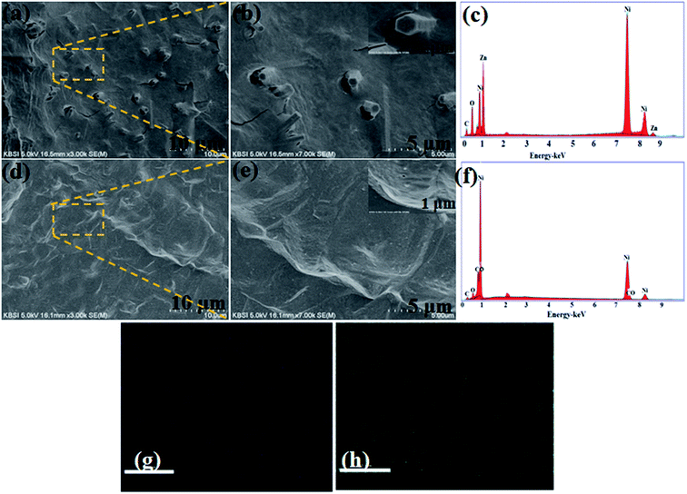 | ||
| Fig. 1 (a and b) FE-SEM images, (c and f) EDX pattern and (d and e) FE-SEM images of NF/ZnOx and NF/CoOx on nickel foam and (g and h) elemental mapping of Zn and O. | ||
The surface morphology and microstructures of the as-prepared NF/ZnOx and NF/CoOx nanostructure electrode materials were examined by field emission scanning electron microscopy (FE-SEM) images. Fig. 1 presents FE-SEM images of NF/ZnOx and NF/CoOx nanostructures deposited on nickel foam substrates at different magnifications using a simple chemical bath deposition approach. FE-SEM (Fig. 1a and b) revealed the as-fabricated NF/ZnOx to have a cone-like nanostructure. As shown in Fig. 1a and b, the NF/ZnOx nanostructure displayed a unique surface morphology with a uniform distribution over the nickel foam substrate, showing a cone-shaped nanostructure with a large surface area. This can augment the transport of electrolyte ions and ensure adequate surface contact between the active material and electrolyte in supercapacitor electrodes, which are beneficial to the redox reaction. Fig. 1c presents the EDX spectrum; the NF/ZnOx was comprised mainly of Zn, Ni, C and O. Fig. 1d and e shows FE-SEM images of NF/CoOx revealing a wave-like nanostructure. The FE-SEM images (Fig. 1d and e) of the NF/CoOx indicated nanoparticles interconnected with each other and distributed uniformly over the Ni foam, which is a beneficial surface for the electrochemical reaction. EDS was also performed to confirm the formation of the NF/CoOx nanostructure, as illustrated in Fig. 1f. The spectrum indicated the presence of Co, Ni, O and C. Moreover, the EDS elemental mapping images further reveal there appears a distribution of Zn and O across the structure (Fig. 1g and h), unambiguously confirming the nanocone structure is attributed to NF/ZnOx.
The structural features of the prepared NF/ZnOx and NF/CoOx samples were examined by HR-TEM, as shown in Fig. 2. HR-TEM clearly resembling the nanoparticle-like morphologies of the synthesized NF/ZnOx and NF/CoOx samples. The mean length and width of the obtained nanocone and nanoparticles were 1 μm, respectively (Fig. 2a and b). The NF/ZnOx had a uniform surface, clear edges, and minor thickness. Therefore, these nanocone and nanoparticle structures are beneficial for efficient and fast ion and electron transportation to the surface of the active materials, which enhance the effective utilization of the active material. The formation of these nanocone and nanoparticle are governed by a range of factors, such as nucleation, grain growth and chemical bath deposition parameters (temperature and time duration). The HR-TEM images which was the individual (111) planes are regularly arranged over the nanoparticles in similar directions as shown in Fig. 2d.
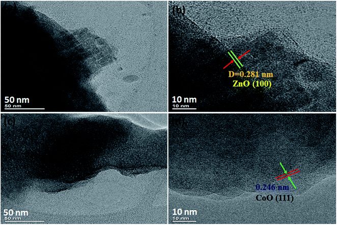 | ||
| Fig. 2 TEM and HR-TEM images of NF/ZnOx and NF/CoOx, (a and b) TEM images of NF/ZnOx, (c and d) TEM images of NF/CoOx. | ||
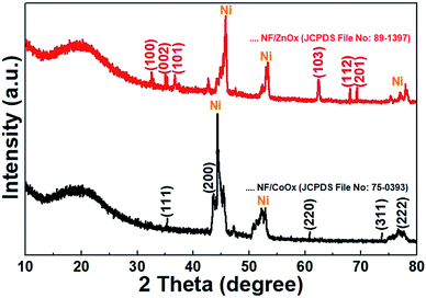
The crystal structure and phase of the NF/ZnOx nanocone and NF/CoOx nanoparticle samples were identified by XRD, and the XRD pattern is shown in Fig. 3. The XRD peaks at 31.7°, 34.2°, 36.2°, 62.8°, 67.9°, and 69.0° 2θ were indexed to the (1 0 0), (0 0 2), (1 0 1) (1 0 3) (1 1 2), and (2 0 1) crystal planes of the ZnO (JCPDS no: 89–1397), respectively.26–28 The peaks at 36.5°, 42.4°, 61.5°, 73.7°, and 77.8° 2θ were assigned to (111), (200), (220), (311), and (222) planes corresponding to the cubic phase of CoO (JCPDS 75-0393).29 The characteristic peaks of the prepared samples were in good agreement with those reported previously. In addition, the strong peaks corresponding to the (111), (200), and (220) crystal planes were indexed to the Ni foam substrate (JCPDS card no. 70-1849).30
Fig. S1a† presents the XPS survey spectra of the NF/ZnOx complete spectrum clearly showing Zn, Ni and O with no other impurities. The presence of Ni in the survey spectrum was attributed to the background of the Ni foam. Fig. S1b† presents the high-resolution XPS spectrum of Zn 2p. The two major peaks at 1022.7 eV and 1045.5 eV were assigned to the Zn 2p3/2 and Zn 2p1/2 peaks of Zn2+ on the nickel foam surface.31 Fig. S1c† presents the Ni 2p spectrum consisting of two major peaks which were the Ni 2p3/2 peaks located at 856.8 eV and 874.4 eV indicates the presence of Ni2+ and Ni3+, respectively; meanwhile, the Ni 2p1/2 peaks were fitted at 862.4 eV and 880.2 eV, which represents the Ni2+ and Ni3+ oxidation states, respectively.32 Furthermore, Fig. S1d† presents the deconvolution spectrum of O 1s. There are three peaks located at eV values of 529.5 (O1), 530.5 (O2), and 531.9 eV (O3); this correspond to the oxy metal bonds and hydroxyl metal bonds.33 Overall, the presence of NF/ZnOx confirmed that the nanocone structure had been prepared successfully. Fig. S2a† presents the XPS survey spectra of the NF/CoOx complete spectrum clearly showing Co, Ni and O. As shown in Fig. S2b† the deconvoluted Co 2p at 780.12 (Co3+ 2p3/2) and 795.2 eV (Co3+ 2p1/2) corresponding to Co3+, and the fittings of Co 2p at 783.6 (Co2+ 2p3/2) and 799.3 eV (Co2+ 2p1/2) can be assigned to Co2+; this proves existence of Co2+ and Co3+ oxidation states in the as-synthesized material. Fig. S2c† presents the Ni 2p spectrum consisting of two major peaks which were the Ni 2p3/2 peaks located at 855.4 eV and 873.6 eV indicates the presence of Ni2+ and Ni3+, respectively; meanwhile, the Ni 2p1/2 peaks were fitted at 862.4 eV and 880.2 eV, which represents the Ni2+ and Ni3+ oxidation states, respectively.32 Fig. S2d† presents deconvolution spectrum of O 1s. The high-resolution scan of the O 1s spectrum showed a peak with a binding energy of 230.8 eV, which is associated with typical metal–oxygen bond.
In order to evaluate the surface area and pore size distribution properties of the as synthesized NF/ZnOx and NF/CoOx electrodes, N2 adsorption–desorption isotherms of BET analysis are shown in Fig. S3a and b.† Uniform distribution of NF/ZnOx ensures higher electrochemically active surface area and hence enhances the electrical conductivity. After analysis, NF/CoOx was found to have minimum surface area and so it was found to have the lowest specific capacitance than the other electrode of NF/ZnOx. The BET surface area and mean pore diameter of NF/CoOx was found to be 65.9 m2 g−1 with an average pore sizes mostly below 5 nm whereas NF/ZnOx showed approximately 79.4 m2 g−1 with an average pore sized mostly below b nm, respectively. This large surface area confirms that the introduction of NF/ZnOx electrode could enhance the specific surface area and increased the reaction sites at the interface of the electrode and the electrolyte significantly.
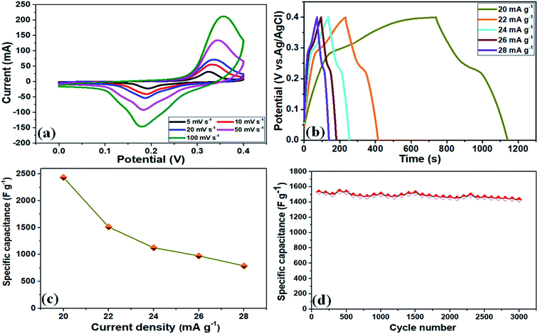
To examine the electrochemical performance and assess the advantages of these NF/ZnOx and NF/CoOx electrode materials, CV, GCD, Cs, and cycling stability were measured in a standard 3-electrode set up using a 2 M KOH aqueous solution as the supporting electrolyte. Fig. 4a presents the CV curves of the NF/ZnOx electrode at various scan rates and potential window between 0 and 0.4 V (vs. SCE). All CV curves revealed a well-defined a pair of redox peaks with increasing scan rate. The CV area increased and a similar CV curve shapes were obtained, indicating pseudocapacitive material. The electrode maintained a uniform and typical redox reaction with a well-defined peak even at higher scan rates (100 mV s−1 from 5 mV s−1). At low-scan rates, most of the inner active sites participate and very high specific capacitance can be obtained. Moreover, the anodic and cathodic peaks shifted toward higher and lower potentials, respectively, due to the insufficient penetration of ions from electrolyte into the dense center of the nanostructure. Fig. 4b presents GCD measurements of the NF/ZnOx electrode carried out at various current densities, ranging from 20 mA g−1 to 28 mA g−1 in the cut-off voltage from 0 to 0.4 V. The entire charge and discharge profiles were symmetrical with different current densities, suggesting that the electrode material exhibits more reversible charge and discharge characteristics.
The specific capacitance of the NF/ZnOx was determined from the discharge curves of the GCD profiles and the corresponding results, as shown in the Fig. 4b. The specific capacitance of the NF/ZnOx electrode material was 2437 F g−1 at 20 mA g−1. Fig. 4c presents GCD plots of NF/ZnOx at different current densities from 20 to 28 mA g−1 in a potential window from 0 to 0.4 V. Fig. 4c displays the calculated specific capacitance based on the discharge current density. The NF/ZnOx electrode showed Cs values of 2437, 1512, 1125, 975, and 787 F g−1 at current densities of 20, 22, 24, 26, and 28 mA g−1, respectively. Therefore, the high specific capacitance and rate capability of as-synthesized NF/ZnOx were attributed to the exclusive porous architecture, which could be useful to shorten the ion-diffusion pathways, enhance the spaces for ion-buffer storage, and offer effective capacitance. The specific capacitance results were higher than the recently reported values of ZnO-based electrodes, such as Co3O4@ZnO nanoheterostructrues (415 F g−1 at 1 A g−1),34 ZnCo2O4 microspheres (542.7 F g−1 at 1 A g−1),35 ZnO nanoflakes (260 F g−1 at 2 A g−1),36 ZnCo2O4 nanostructure (776.2 F g−1 at 1 A g−1)37 and ZnO@Co3O4 core/shell heterostructure (857.7 F g−1 at 1 A g−1),38 respectively. Moreover, the cycling stability of the NF/ZnOx was examined at a current density of 22 mA g−1. The NF/ZnOx showed good capacitance retention of 97.8% after 3000 cycles, highlighting its remarkable long-term cycling stability, as shown in (Fig. 4d).
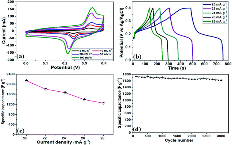
The electrochemical performance of the NF/CoOx electrode material was also analyzed by CV, GCD, Cs, and cycling stability measurements. Fig. 5a and b presents the CV and GCD curves of the NF/CoOx electrode. The NF/CoOx exhibited a specific capacitance of 2142, 1807, 1670, 1392, and 1250 F g−1 at current densities of 20, 22, 24, 26, and 28 mA g−1, respectively (Fig. 5c). The specific capacitance of the NF/CoOx electrode exhibited superior performance to other previously reported CoO-based electrodes with Co3O4 nanostructure (637.2 F g−1 at 2 A g−1),39 Co3O4 nanotube (574 F g−1 at 2 A g−1),40 Co3O4 nanorod (456 F g−1 at 1 A g−1),41 Co3O4/graphene (328 F g−1 at 1 A g−1)42 and Co3O4 nanocubes (833 F g−1 at 50 mV s−1),43 respectively. In addition, long cycling behavior is another important factor for the practical prospects of a supercapacitor. Fig. 5d presents the cycling performance of the as-prepared NF/CoOx at 22 mA g−1 over 3000 cycles. A gradual enhancement in cycling behavior was observed due to the occurrence of an activation process with the electrolyte penetrating into the inner parts of materials. After 3000 cycles, the NF/CoOx electrode still retained 95.8% of its initial capacitance.
EIS was performed on NF/ZnOx and NF/CoOx electrode materials over the frequency range, 0.1 Hz to 100 kHz, to further investigate the electrochemical behavior, and the corresponding EIS plots are shown in Fig. 6a. All the curves included a partial semicircle in the high frequency region, corresponding to the charge transfer resistance, and an inclined line along the imaginary axis in the low frequency region, suggesting excellent electrical conductivity due to rapid ion and electron transport in the electrode, which leads to superior performance. The charge transfer resistance (Rct) of the NF/ZnOx and NF/CoOx electrodes were low at 0.2 Ω and 0.4 Ω, respectively. The energy density (E) and power density (P) are generally used as important parameters to characterize the performance of supercapacitor applications. The Ragone plots of NF/ZnOx and NF/CoOx is shown in Fig. 6b. Impressively by using eqn (2) and (3), the NF/ZnOx and NF/CoOx exhibited a high energy density (E) of 54.15 W h kg−1 and 47.6 W h kg−1 at a power densities (P) of 499.8 W kg−1 and 571.2 W kg−1, respectively, highlighting the excellent energy storage performance of NF/ZnOx and NF/CoOx. Remarkably, these obtained values are substantially superior than the reported values for the AC‖Al–Co oxide,44 AC‖Ni–Co oxide,45 AC‖Fe3O4,46 AC‖MnO2 (ref. 47) and AC‖(Ni1/3Co1/3Mn1/3)(OH)2 (ref. 48) asymmetric capacitors with identical experimental conditions to those employed here. The high energy density should be attributed to both its high specific capacitance and its wide electrochemical window in the aqueous electrolyte.
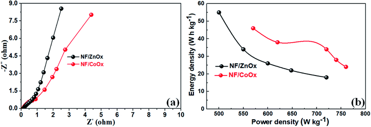 | ||
| Fig. 6 (a) Electrochemical impedance spectra (EIS) and (b) Ragone plots of the NF/ZnOx and NF/CoOx electrodes. | ||
Conclusion
NF/ZnOx and NF/CoOx electrode materials were fabricated using a simple chemical bath deposition approach for high energy-storage performance. These NF/ZnOx and NF/CoOx electrodes evaluated for supercapacitors delivered much enhanced electrochemical behaviors and enhanced the use of active material and provided a greater electrical conductivity and faster kinetics. The fabricated NF/ZnOx and NF/CoOx SCs devices exhibited a good specific capacitance of 2437 and 2142 F g−1 at a current density of 20 mA g−1, respectively, and exhibited outstanding cycling performance with 97.8% and 95.8% specific capacitance retention, respectively, after 3000 cycles at a current density of 22 mA g−1. The electrodes exhibited a high specific surface area, low Rct value, and good cycling performance, highlighting their potential applicability for high performance energy storage applications for the future.Conflicts of interest
There are no conflicts to declare.Acknowledgements
This work was financially supported by BK 21 PLUS, Creative Human Resource Development Program for IT Convergence (NRF-2015R1A4A1041584), Pusan National University, Busan, South Korea. We would like to thank KBSI, Busan for SEM, TEM, XRD, XPS and EDX analysis.References
- Y. Huang, H. Li, Z. Wang, M. Zhu, Z. Pei, Q. Xue, Y. Huang and C. Zhi, Nano Energy, 2016, 22, 422–438 CrossRef CAS.
- Y. A. Kumar, A. E. Reddy and H.-J. Kim, Energies, 2019, 12, 1308 CrossRef.
- D. Zhang, Y. Zhang, Y. Luo and P. K. Chu, Nano Energy, 2015, 13, 47–57 CrossRef CAS.
- Y. A. Kumar, S. S. Rao, D. Punnoose, C. V. Thulasivarma, C. V. V. M. Gopi, K. Prabakar and H.-J. Kim, R. Soc. Open Sci., 2017, 4, 170427 CrossRef.
- X. Meng, H. Sun, J. Zhu, H. Bi, Q. Han, X. Liu and X. Wang, New J. Chem., 2016, 40, 2843–2849 RSC.
- L. Wang, X. Feng, L. Ren, Q. Piao, J. Zhong, Y. Wang, H. Li, Y. Chen and B. Wang, J. Am. Chem. Soc., 2015, 137, 4920–4923 CrossRef CAS.
- H. Hu, B. Guan, B. Xia and X. W. Lou, J. Am. Chem. Soc., 2015, 137, 5590–5595 CrossRef CAS.
- A. K. Yedluri and H.-J. Kim, Dalton Trans., 2018, 47, 15545–15554 RSC.
- J. Y. Lin and S. W. Chou, RSC Adv., 2013, 3, 2043–2048 RSC.
- Q. Wang, Y. Ma, X. Liang, D. Zhang and M. Miao, J. Mater. Chem. A, 2018, 6, 10361–10369 RSC.
- W. Yang, X. Li, Y. Li, R. Zhu and H. Pang, Adv. Mater., 2018, 31, 1804740 CrossRef.
- Y. Li, Y. Xu, W. Yang, W. Shen, H. Xue and H. Pang, Small, 2018, 14, 1704435 CrossRef.
- J. Zhang, P. Gu, J. Xu, H. Xue and H. Pang, Nanoscale, 2016, 8, 18578–18595 RSC.
- Y. Yan, P. Gu, S. Zheng, M. Zheng, H. Pang and H. Xue, J. Mater. Chem. A, 2016, 4, 19078–19085 RSC.
- Y. A. Kumar and H.-J. Kim, New J. Chem., 2018, 42, 19971 RSC.
- I. Shown, A. Ganguly, L. C. Chen and K. H. Chen, Energy Sci. Eng., 2015, 3, 2–26 CrossRef CAS.
- N. Choudhary, C. Li, J. Moore, N. Nagaiah, L. Zhai, Y. Jung and J. Thomas, Adv. Mater., 2017, 29, 1605336 CrossRef.
- J. Xu, S. Liu and Y. Liu, RSC Adv., 2016, 6, 52137–52142 RSC.
- D. Bekermann, A. Gasparotto, D. Barreca, C. Maccato, E. Comini, C. Sada, G. Sberveglieri, A. Devi and R. A. Fischer, ACS Appl. Mater. Interfaces, 2012, 4, 928 CrossRef CAS.
- S. K. Meher and G. R. Rao, J. Phys. Chem. C, 2011, 115, 15646 CrossRef CAS.
- W. Liu, X. Li, M. Zhu and X. He, J. Power Sources, 2015, 282, 179–186 CrossRef CAS.
- Z. Xiao, L. Fan, B. Xu, S. Zhang, W. Kang, Z. Kang, H. Lin, X. Liu, S. Zhang and D. Sun, ACS Appl. Mater. Interfaces, 2017, 9, 41827–41836 CrossRef CAS PubMed.
- N. Zhang, X. Yan, J. Li, J. Ma and D. Ng, Electrochim. Acta, 2017, 226, 132–139 CrossRef CAS.
- B. Pant, M. Park, G. P. Ojha, J. Park, Y. S. Kuk, E. J. Lee, H. Y. Kim and S. J. Park, J. Colloid Interface Sci., 2018, 522, 40–47 CrossRef CAS.
- L. S. Aravinda, K. K. Nagaraja, H. S. Nagaraja, K. U. Bhat and B. R. Bhat, Electrochim. Acta, 2013, 95, 119–124 CrossRef CAS.
- A. K. Yedluri, T. Anitha and H.-J. Kim, Energies, 2019, 12, 1143 CrossRef.
- Y. A. Kumar and H.-J. Kim, Energies, 2018, 11, 3285 CrossRef CAS.
- J. Hao, X. Wang, F. Liu, S. Han, J. Lian and Q. Jiang, Sci. Rep., 2017, 7, 3021 CrossRef.
- C. Zheng, C. Cao, Z. Ali and J. Hou, J. Mater. Chem. A, 2014, 2, 16467–16473 RSC.
- J. Hao, X. Wang, F. Liu, S. Han, J. Lian and Q. Jiang, Sci. Rep., 2017, 7, 3021 CrossRef.
- H. Borchert, S. Haubold, M. Haase, H. Weller, C. McGinley, M. Riedler and T. Moller, Nano Lett., 2002, 2, 151–154 CrossRef CAS.
- A. Urbano, S. C. Castro, R. Landers, J. Morais, A. D. Siervo, A. Gorenstein, M. H. Tabacniks and M. C. A. Fantini, J. Power Sources, 2001, 97, 328–331 CrossRef.
- F. Parimigiani and L. Sangaletti, J. Electron Spectrosc. Relat. Phenom., 1999, 98, 287–302 CrossRef.
- J. Xu, S. Liu and Y. Liu, RSC Adv., 2016, 6, 52137 RSC.
- Y. Y. Gai, Y. Shang, L. Gong, L. Su, L. Hao, F. Dong and J. Li, RSC Adv., 2017, 7, 1038–1044 RSC.
- B. Pant, M. Park, G. P. Ojha, J. Park, Y. S. Kuk, E. J. Lee, H. Y. Kim and S. J. Park, J. Colloid Interface Sci., 2018, 522, 40–47 CrossRef CAS PubMed.
- L. Xu, Y. Zhao, J. Lian, Y. Xu, J. Bao, J. Qiu, L. H. Xu, M. Hua and H. Li, Energy, 2017, 123, 296–304 CrossRef CAS.
- Y. A. Kumar and H.-J. Kim, RSC Adv., 2019, 9, 1115 RSC.
- D. Cai, H. Huang, D. Wang, B. Liu, L. Wang, Y. Liu, Q. Li and T. Wang, ACS Appl. Mater. Interfaces, 2014, 6, 15905–15912 CrossRef CAS.
- D. Mohapatra, S. Parida, S. Badrayyana and B. K. Singh, Appl. Mater. Today, 2017, 7, 212–221 CrossRef.
- L. Cui, J. Li and X. G. Zhang, J. Appl. Electrochem., 2009, 39, 1871 CrossRef CAS.
- M. H. Yang and B. G. Choi, Chem. Eng. Commun., 2017, 204, 723–728 CrossRef CAS.
- R. Samal, B. Dash, C. K. Sarangi, K. Sanjay, T. Subbaiah, G. Senanayake and M. Minakshi, Nanomaterials, 2017, 7, 356 CrossRef.
- Y.-G. Wang, L. Cheng and Y.-Y. Xia, J. Power Sources, 2006, 153, 191–196 CrossRef CAS.
- C. Tang, Z. Tang and H. Gong, J. Electrochem. Soc., 2012, A651–A656 CrossRef CAS.
- X. Du, C. Wang, M. Chen, Y. Jiao and J. Wang, J. Phys. Chem. C, 2009, 113, 2643–2646 CrossRef CAS.
- A. Yuan and Q. Zhang, Electrochem. Commun., 2006, 8, 1173–1178 CrossRef CAS.
- Y. Zhao, Y. Lai, J. Hao and Y. Ji, J. Alloys Compd., 2009, 471, 466–471 CrossRef CAS.
Footnote |
| † Electronic supplementary information (ESI) available. See DOI: 10.1039/c9ra01809c |
| This journal is © The Royal Society of Chemistry 2019 |

