 Open Access Article
Controlling the nucleophilic properties of cobalt salen complexes for carbon dioxide capture†
Meliton R. Chiong III *ab and
Francis N. C. Paraan
 b
b
aMaterials Science and Engineering Program, University of the Philippines Diliman, Quezon City, Philippines. E-mail: mrchiong@msep.upd.edu.ph
bNational Institute of Physics, University of the Philippines Diliman, Quezon City, Philippines
First published on 26th July 2019
Abstract
The nucleophilic properties of cobalt salen complexes are examined using density functional theory to investigate its carbon fixing capacity. In particular, carbon dioxide attack on neutral and anionic cobalt salen molecules is considered. Carbon fixation occurs for the anionic cobalt salen complex and is due to the nucleophilic interaction between the cobalt center and carbon dioxide molecule in a Co dz2–CO2 π* interaction. A minimum energy path search by a nudged elastic band calculation reveals a lower forward activation energy for the anionic complex than the neutral complex, indicating that the formation of the anionic complex is thermodynamically and kinetically favored. In this case, the CO2 molecule is chemisorbed as partial charge transfer from the cobalt center to carbon dioxide is observed. Proposed reaction mechanisms explain how the Co–C bond energy of the CO2–cobalt salen complex can be tuned by appropriate substitutions of electron donating or withdrawing groups on the phenyl ring.
1 Introduction
The capture of carbon dioxide (CO2) by appropriate catalysts and its eventual conversion by electrochemical reduction into a wide range of value-added products such as methane, methanol, carbon monoxide, and formic acid has received great attention.1 Several studies have been done in order to search for and understand the interaction of CO2 with different surface and molecular catalysts.2 Hori made a comprehensive investigation of the different reaction products of CO2 reduction by different metal surfaces3 and since then, metal-surface mediated CO2 reduction has been widely studied. Recent studies worked on improving the catalytic performance of metals by modifying and incorporating surface nanostructures.4,5Aside from employing metal surfaces as heterogeneous catalysts, organometallic complexes with transition metal centers can also be used as homogeneous catalysts.6 This offers another possibility of improving catalytic performance by tailoring the molecular structure of the ligand. Understanding the structure and functional models of transition metal–carbon dioxide complexes is important in probing the surface-bound intermediates in catalytic processes. Although initially identified as a poor ligand, CO2 has demonstrated outstanding versatility by exhibiting various coordination modes. Different coordination compounds formed by CO2 has been synthesized in recent years.7,8 The nomenclature of these compounds includes a description of hapticity, the number of contiguous atoms coordinated to the metal by the ligand, indicated by ηn, where n is the number of atoms involved in a coordination bond.
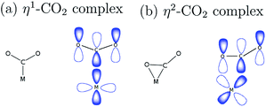
Metal centers that have coordination vacancy or ligands that are good leaving groups are capable of forming a complex with the weakly electrophilic CO2, as illustrated in Fig. 1. In η1–CO2 complex, the metal center forms a bond with CO2 through carbon directly.9 This bonding is characterized by the overlap of orbitals of an electron-rich metal center and a ligand that has the same symmetry label, forming a σ-bond. In η2–CO2 complex, both carbon and oxygen atoms of CO2 form a bond with the metal center. This is characterized by a π-type interaction of the metal and ligand.
Common organic ligands that are used as catalysts include phthalocyanine, porphyrin, and cyclam.10–12 These tetradentate ligands offer possible binding sites in the axial positions as they form square planar metal complexes. Cobalt porphyrin complex was reported as a possible electrocatalyst in the reduction of CO2 to methane.13 Density functional theory (DFT) and ab initio molecular dynamics studies reported that the electrocatalytic reduction of CO2 to CO by cobalt porphyrin proceeds via a Co(porphyrin)–COOH intermediate.14,15 However, the use of a tetradentate Schiff-base ligand as an electrocatalyst has not been extensively studied. Schiff-base ligands such as N,N′-bis(salicylaldehyde)-ethylenediimino ligand, abbreviated as salen, are coordinated to the metal center by phenolate oxygen and imine nitrogen which extend the conjugation of the phenyl ring. Fig. 2 shows the structure of cobalt salen complex. A study by Gambarotta et al. investigated the carbon capture behavior of a bifunctional salen ligand complex containing Co(I) and an alkali cation.16 It was recently demonstrated experimentally that Ni(II)(salen) and Cu(II)(salen) complexes can act as very efficient electrocatalysts for the electrocatalytic reduction of CO2.17
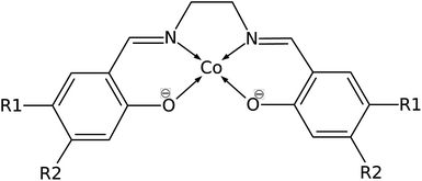 | ||
| Fig. 2 Structure of Co(salen) (R1 = R2 = H), salen = N,N′-bis(salicylaldehyde)-ethylenediimino ligand. R1 and R2 are sites for substitution. | ||
The possibility of Co(salen) as an electrocatalyst can be examined because it is a square-planar complex with axial sites available for carbon fixation, and because it contains aromatic rings that can be exploited to control the electron density of the complex. Aromatic substitution with electron withdrawing or donating groups can affect the electron density and reactivity of the metal center. Thus, the substitution may provide an effective way to tune the affinity of carbon capture of organometallic complexes in electrocatalysis.
In this study, a theoretical investigation of the binding of carbon dioxide to cobalt salen complex, Co(salen), is examined using density functional theory (DFT). This paper is organized as follows. In Section 2 we present theoretical and computation details of our work. In Section 3, we report a stable structure formed by CO2 and the anionic [Co(salen)]−. In Section 4 we further examined the binding process by analyzing the electronic structure of the complex and the orbital overlap of CO2 and Co. In Section 5, we discuss how the bond energy is manipulated by substituting electron donating or withdrawing groups on the ligand. Finally, we summarize our findings in Section 6.
2 Computational details
DFT calculations were done using the generalized gradient approximation (GGA) with the Perdew–Burke–Ernzerhof (PBE) exchange–correlation functional.18 We used a plane-wave basis set and the pseudopotential method with ultrasoft pseudopotentials to obtain fairly accurate structural results at a lower computational cost.19–21 To ensure the completeness of this basis, the kinetic energy cutoff was set to 45 Ry (450 Ry for the charge density cutoff) in which the variation in the total energy of the self-consistent field calculation was below 0.001 eV.The bound CO2 and Co(salen) system was modeled by indicating the position of the CO2 molecule where the C atom is on top of the Co atom so that the complex is characterized by a η1–C coordination. We considered both neutral Co(salen) and anionic [Co(salen)]− complexes, as well as their CO2-bound forms. Geometry optimization of these structures was done by fully optimizing all structural parameters until the forces on each atom is below 0.001 Ry Å−1. For a charged system, Makov–Payne correction was employed in order to achieve faster convergence.22 The size of the simulation box was set to 30 × 30 × 30 bohr3 to ensure enough vacuum space between mirror images. This was done by increasing the dimensions of the cubic box until the variation in the total energy is less than 0.01 Ry. Brillouin zone sampling was performed at the Γ-point and treated with Gaussian smearing using a smearing parameter of 0.01 Ry.
Nudged elastic band calculation was done with climbing image scheme to search the minimum energy path and transition state structure of the formation of Co(salen)–CO2 and [Co(salen)–CO2]− adducts.23 The transition state image maximizes its energy along the band (reaction coordinate) and minimizes in all other directions. The activation energy of an elementary step can be obtained from the first-order saddle point of the potential energy surfaces, which corresponds to the highest energy along the minimum energy path.
The charge transfer between CO2 and the complex is characterized by the charge density difference defined as
| Δn(r) = nCO2/Co(salen)(r) − [nCO2(r) + nCo(salen)(r)] | (1) |
The bond energy is calculated using
| Ebond = ECo(salen)–CO2 − ECo(salen) − ECO2 | (2) |
The calculations were performed using the pwSCF package of Quantum ESPRESSO,24 while postprocessing and visualization were done with the XCrySDen package.25
3 Structural properties
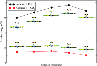
Upon relaxation of the Co(salen)–CO2 structure, the CO2 molecule was unable to form a stable bond with the neutral Co(salen) complex. Any attempt to optimize the geometry of the different Co–CO2 coordination modes, including η1(C), η1(O), and η2(C,O), resulted in separate Co(salen) and CO2 molecules. On the other hand, the CO2 molecule was able to form a stable bond with the anionic [Co(salen)]− complex. The equilibrium Co–C distance of the [Co(salen)–CO2]− adduct is 2.189 Å (Fig. 4).A climbing-image nudged elastic band (CI-NEB) calculation with five images was done, where the initial and final images were fixed corresponding to the unbound and bound adducts, respectively. In the formation of the hypothetical, neutral Co(salen)–CO2 adduct, the initial image was chosen to correspond to the unbound Co(salen) and CO2 molecules resulting from the geometry relaxation. Since a stable Co(salen)–CO2 was not attained, the final image was chosen to have its atomic coordinates identical to those of the relaxed [Co(salen)–CO2]− adduct, and its total charge adjusted to zero. In the formation of the anionic [Co(salen)–CO2]− adduct, the initial and final images were chosen by relaxing both unbound and bound molecules, respectively.
As shown in Fig. 3, the energy of the bound Co(salen)–CO2 adduct is relatively higher than the unbound state, signifying that the unbound state is more stable than the bound state. Moreover, the CI-NEB calculation shows an activation energy barrier of 0.828 eV associated with the formation of bound Co(salen)–CO2, while the formation of [Co(salen)–CO2]− from its unbound structures proceeds with a lower activation energy barrier of 0.042 eV. Furthermore, the energy of the bound [Co(salen)–CO2]− is relatively lower than its unbound structures. Therefore, the formation of the anionic [Co(salen)–CO2]− adduct is both thermodynamically and kinetically favorable.
Fig. 4 shows the DFT-optimized structure of [Co(salen)–CO2]− complex. The structural parameters are listed in Table 1. Both C–O bond lengths of the bent CO2 are 1.217 Å and O–C–O bond angle is 143.5°. In this case, a η1(C)–CO2 complex is formed due to the formation of Co–C σ bond. The closest available structural data is obtained from Co(n-Pr-salen)(CO2)K(THP) where O–C–O bond angle is 132.0–134.9°, C–O bond lengths of 1.20–1.24 Å, and Co–C bond length of 1.99–2.00 Å.16 The deviation of the calculated values from experiment may be due to the additional stabilization by K+ cation as it acts as a Lewis base by coordinating with the oxygen atom of the CO2 molecule. The transition state structure for the formation of [Co(salen)–CO2]− adduct is shown in Fig. S1 in the ESI,† with a Co–C bond length of 2.666 Å and O–C–O bond angle of 154.7°, as the CO2 molecule slowly approaches the Co atom and the O–C–O bond slowly bends.
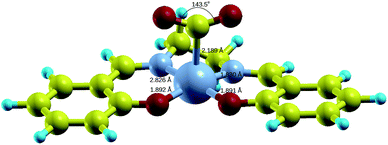 | ||
| Fig. 4 Relaxed structure of [Co(salen)–CO2]− complex. Yellow = C, cyan = H, red = O, small gray = N, big gray = Co. | ||
| Parameter | Unbound [Co(salen)]− and CO2 | Bound [Co(salen)–CO2]− |
|---|---|---|
| Co–N1 bond length (Å) | 1.796 | 1.826 |
| Co–N2 bond length (Å) | 1.795 | 1.830 |
| Co–O1 bond length (Å) | 1.888 | 1.892 |
| Co–O2 bond length (Å) | 1.889 | 1.891 |
| Co–C bond length (Å) | — | 2.189 |
| O–C–O bond angle (deg) | 180 | 143.5 |
| CO2 partial charge | +0.125e | −0.430e |
| Co partial charge | +0.079e | +0.154e |
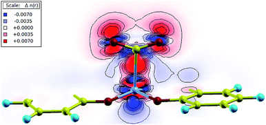
Bader charge analysis was performed in order to measure the partial charge associated with each atom.26 During the binding process, partial charges were redistributed from the Co atom to the CO2 molecule, as the partial charge on Co increased while that of CO2 decreased. Charge transfer was also visualized in the charge density difference plot of the Co–CO2 plane as shown in Fig. 5. There was an increased accumulation of charge in the region between carbon and cobalt (red region), indicating an enhanced chemical bonding. The charges were redistributed from blue to red regions, showing a depleted electron density associated with cobalt, and increased electron density associated with carbon dioxide. Furthermore, the loss of linearity of CO2 is associated with the formation of the CO2˙− radical anion as the metal center is oxidized from Co(I) to Co(II) accompanying the charge transfer. The stabilization of the complex resembles a metal-to-ligand charge transfer occurring in the nucleophilic attack of Co to the electrophilic carbon.27–29
4 Electronic properties
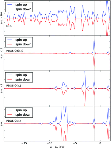
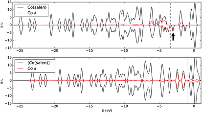
In order to understand the binding process, we further examine the interaction between cobalt and CO2 electronic states using molecular orbitals. Fig. 6 shows the molecular orbital representation of the HOMO and HOMO − 1 of both [Co(salen)]− and [Co(salen)–CO2]− adducts. From the figure, a bonding molecular orbital is observed in HOMO − 1 of the latter. This is also consistent with Fig. 5, where charges accumulate between cobalt and carbon atoms to form a σ bond. Furthermore, the total density of states shown in Fig. 7 are the same for both spin polarizations. This indicates that the adduct is diamagnetic. Thus, our structure has no net magnetization and the binding of CO2 is mainly due the orbital and electrostatic interactions with Co.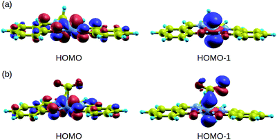 | ||
| Fig. 6 HOMO and HOMO − 1 of (a) [Co(salen)]− and (b) [Co(salen)–CO2]− complex. Bonding MO is observed in HOMO − 1. | ||
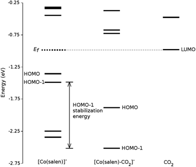
We analyze this orbital overlap by projecting the total density of states onto the atomic orbitals (PDOS). The vertical line on Fig. 7 marks the HOMO − 1 state. The PDOS data showed that Co dz2, O pz, and C pz have significant contribution to this state. The square modulus of the overlap matrix of the HOMO − 1 orbital with these orbitals are 0.567, 0.119, and 0.018, respectively. The O pz and C pz orbitals primarily constitute the CO2 π* orbital.30 Thus, the formation of the η1–CO2 σ bond is mainly due to the back-donation of electrons from the Co dz2 orbital to the CO2 π*, typical for compounds which have low-lying empty π* LUMO.31 As shown in Fig. 8, the LUMO of CO2 coincides well with the Fermi level of [Co(salen)]−. This orbital alignment explains the ease of back-donation and charge transfer. The stabilization brought by the back-bonding and partial charge transfer is due to the lowering of the HOMO − 1 level (HOMO − 1 stabilization energy) by 0.621 eV and a corresponding Co–C bond energy of 19.63 kJ mol−1.
A way to explain why the CO2 molecule forms a stable bond with the anionic [Co(salen)]−, and not with the neutral Co(salen) complex, is by analyzing their respective electronic structures before carbon capture. The spin-polarized density of states of both Co(salen) and [Co(salen)]− complexes are shown in Fig. 9. For the neutral Co(salen) complex, the cobalt center has a +2 state with an unpaired electron (d7, S = 0), and a Fermi energy of −3.325 eV. The local density of Co d states is polarized near the Fermi level, and a spin minority state exists in the midgap region. Upon the initial reduction of Co(salen) to [Co(salen)]−, the Co(II) atom is reduced to Co(I) and the complex becomes non-ferromagnetic as the density of states for both spins are the same (S = 1). Here, the d states of the [Co(salen)]− complex comprise most of HOMO and HOMO − 1. Furthermore, the Fermi energy for the anionic complex increases to −1.0025 eV, allowing the frontier orbitals to have a good overlap with the π* LUMO of the CO2 molecule. The additional electron also contributes to the electron–electron repulsion, decreasing the effective nuclear charge experienced by the valence electrons, which explains the increase in Fermi energy. Hence, the additional electron in the anionic [Co(salen)]− facilitates CO2 capture by bringing the frontier orbitals closer to the LUMO of the CO2 molecule.
5 Nucleophilic properties of phenyl substituted [Co(salen)]−
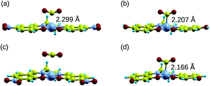
Manipulating the nucleophilicity of the cobalt center gives rise to the possibility of tuning the chemisorption strength of CO2 to [Co(salen)]− by controlling the electron density on the cobalt center. Because the salen ligand is coordinated to the cobalt center with its imine nitrogen and phenolic oxygen, activating or deactivating the conjugated phenyl ring with electron donating or withdrawing groups will affect the electron density on these atoms and on cobalt. Thus, the nucleophilicity of cobalt, a measure of its extent to donate electrons to an electrophile, will be affected by the change in its electron density.We investigate the changes in nucleophilic properties of [Co(salen)]− by substituting –NO2 and –OH groups as electron withdrawing and donating groups, respectively, on the phenyl rings. Two substitution sites, R1 and R2, were considered, as shown in Fig. 2. These sites were chosen to account for both para- and meta-substitution of the phenyl ring with respect to the phenolic oxygen. Table 2 shows the HOMO − 1 stabilization energy, bond energy, Co–C distance, and charge density on cobalt atom for both unsubstituted and substituted [Co(salen)]−. Fig. 10 shows the relaxed structure of phenyl-substituted [Co(salen)–CO2]−. On R1, substituting –NO2 significantly weakens the bond as shown by a decrease in bond and HOMO − 1 stabilization energies, while substituting –OH has little effect on these properties. The weakening is also accompanied by an increase in Co–C bond length and charge density on cobalt. On the other hand, substituting R2 with –NO2 has similar weakening effect on R1 as no Co–C bond is formed. However, the decreased Co–C bond distance upon substituting –OH on R2 signifies an increased bond strength and HOMO − 1 stabilization energy.
| Unsubstituted | R1 | R2 | |||
|---|---|---|---|---|---|
| –NO2 | –OH | –NO2 | –OH | ||
| HOMO − 1 stabilization energy (eV) | 0.621 | 0.440 | 0.608 | 0.062 | 0.721 |
| Bond energy (kJ mol−1) | 19.63 | 2.23 | 18.32 | 4.06 | 23.48 |
| Co–C bond distance (Å) | 2.189 | 2.299 | 2.207 | — | 2.166 |
| Charge density on cobalt (×10−3 bohr−3) | +0.725 | +0.809 | +0.728 | +1.268 | +0.565 |
In order to explain these trends, we propose a mechanism of charge delocalization involving the electron withdrawing and donating groups on the phenyl rings and the cobalt center using its resonance structures. Fig. 11(a) shows how the –NO2 group on R1 withdraws electrons from the phenolic oxygen, decreasing the density of electrons on the oxygen atom that is coordinated to the cobalt center. Hence, we see an increased positive charge density as electrons on the cobalt center are withdrawn, which decreases its nucleophilicity. This weakens the carbon fixing capacity of cobalt as less electrons are now available for back-bonding. Substituting –NO2 on R2 has a similar effect as electrons are withdrawn from the imine nitrogen as shown in Fig. 12(a). The withdrawal of electrons leaves nitrogen with an incomplete valence shell, thereby decreasing the density of electrons that is coordinated to the cobalt center. The decrease in electron density causes the cobalt atom to be less polarizable, making it a “hard” Lewis base which does not form a strong bond with a “soft” Lewis acid such as carbon dioxide.32
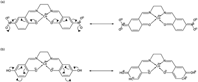 | ||
| Fig. 11 (a) Substitution on R1 with –NO2 decreases electron density on cobalt, while (b) substituting with –OH has no significant effect. | ||
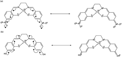 | ||
| Fig. 12 (a) Substitution on R2 with –NO2 decreases electron density on cobalt, while (b) substituting with –OH increases it. | ||
In Fig. 11(b), on the other hand, the electron donating effect of the –OH group on R1 is only confined within the phenyl ring and does not affect the charge density of the phenolic oxygen as the latter already has full valency. Thus, electron donating groups on R1 have little effect on the nucleophilicity of cobalt. For the OH-substituted phenyl ring in Fig. 12(b), the established resonance structure enables the increased electron density on imine nitrogen. This electron delocalization increases the available electrons coordinated to cobalt so that the positive charge density on cobalt decreases, making it more nucleophilic. The increased nucleophilicity on cobalt forms a stronger Co–C bond and leads to an increase in the HOMO − 1 stabilization energy.
Therefore, the carbon fixing capacity of [Co(salen)]− can easily be controlled by substituting electron withdrawing and donating groups on the appropriate locations. Electron donating groups para to the imine group strengthen the Co–C bond, while electron withdrawing groups in general weaken it. Similarly, functional groups which have similar effect as either –NO2 and –OH can be substituted in order to achieve the desired Co–C bond strength. These phenyl substitutions allow one to tune the carbon fixing capacity of [Co(salen)]− while improving its selectivity and specificity as a homogeneous catalyst for the electrochemical reduction of CO2.
6 Conclusions
We presented a theoretical model that predicts carbon dioxide capture on Co(salen) after reducing this organometallic catalyst to [Co(salen)]−. The bonding favors the formation of an η1–C mode where a σ bond is formed by the overlap of the Co dz2 and CO2 π* orbitals. Additionally, this bonding is accompanied by a partial charge transfer due to the back-donation of electrons to the low-lying LUMO of CO2, since it lies very close to the Fermi energy of [Co(salen)]−. The interaction of CO2 with the complex lowers the energy of the HOMO − 1 orbital by approximately 0.621 eV. Altering the charge density around the phenyl rings of the catalyst affects the nucleophilicity of the cobalt center so that electron withdrawing groups weaken the Co–C bond strength. Meanwhile, electron donating groups in the para position with respect to the imine nitrogen increases the nucleophilicity of the cobalt center. The theoretical treatment done here can be refined further in future work to account for solvation effects by using a polarizable continuum model, employing hybrid functionals, and applying van der Waals corrections to the dispersion interaction. Still, the results of this study provide a sound basis for the experimental investigation of the electrochemical reduction of CO2 by Co(salen) and other similar organometallic catalysts.Conflicts of interest
There are no conflicts to declare.Acknowledgements
MRC acknowledges the support of the DOST-SEI through its ASTHRDP Scholarship. This work is supported by the UP System Enhanced Creative Work and Research Grant ECWRG 2018-1-009.References
- J. Qiao, Y. Liu, F. Hong and J. Zhang, Chem. Soc. Rev., 2014, 43, 631–675 RSC.
- B. Khezri, A. C. Fisher and M. Pumera, J. Mater. Chem. A, 2017, 5, 8230–8246 RSC.
- Y. Hori, Electrochemical CO2 reduction on metal electrodes, Springer, New York, 2008, vol. 42, pp. 89–189 Search PubMed.
- Y. Zhao, C. Wang and G. G. Wallace, J. Mater. Chem. A, 2016, 4, 10710–10718 RSC.
- A. Eilert, F. S. Roberts, D. Friebel and A. Nilsson, J. Phys. Chem. Lett., 2016, 7, 146–1470 Search PubMed.
- R. Francke, B. Schille and M. Roemelt, Chem. Rev., 2018, 4631–4701 CrossRef CAS PubMed.
- M. Aresta, C. F. Nobile, V. G. Albano, E. Forni and M. Manassero, J. Chem. Soc., Chem. Commun., 1975, 636–637 RSC.
- K. Pandey, Coord. Chem. Rev., 1995, 140, 37–114 CrossRef CAS.
- J. Mascetti, Carbon dioxide as chemical feedstock, Wiley-VCH & Co., Weinheim, 2010, ch. 4, pp. 55–88 Search PubMed.
- T. Yoshida, K. Kamato, M. Tsukamoto, T. Iida, D. Schlettwein, D. Wohrle and M. Kaneko, J. Electrochem. Soc., 1995, 385, 209–225 Search PubMed.
- N. Sonoyama, M. Kirii and T. Sakata, Electrochem. Commun., 1999, 1, 213–216 CrossRef CAS.
- M. Beley, J. P. Collin, R. Ruppert and J. P. Sauvage, J. Am. Chem. Soc., 1986, 108, 7461–7467 CrossRef CAS PubMed.
- J. Shen, M. J. Kolb, A. J. Gottle and M. T. M. Koper, J. Phys. Chem. C, 2016, 120, 15714–15721 CrossRef CAS.
- I. Nielsen and K. Leung, J. Phys. Chem. A, 2010, 114, 10166–10173 CrossRef CAS PubMed.
- K. Leung, I. Nielsen, N. Sai, C. Medforth and J. A. Shelnutt, J. Phys. Chem. A, 2010, 114, 10174–10184 CrossRef CAS PubMed.
- S. Gambarotta, F. Arena, C. Floriani and P. F. Zanazzi, J. Am. Chem. Soc., 1982, 104, 5082–5092 CrossRef CAS.
- S. Singh, B. Phukan, C. Mukherjee and A. Verma, RSC Adv., 2015, 5, 3581–3589 RSC.
- J. P. Perdew, K. Burke and M. Ernzerhof, Phys. Rev. Lett., 1996, 77, 3865–3868 CrossRef CAS PubMed.
- W.-L. Yim and T. Klüner, J. Comput. Chem., 2008, 29, 1306–1315 CrossRef CAS PubMed.
- E. Maggio, P. Liu, M. J. van Setten and G. Kresse, J. Chem. Theory Comput., 2017, 13, 635–648 CrossRef CAS PubMed.
- C. Massobrio and E. Ruiz, Monatsh. Chem., 2003, 134, 317–326 CrossRef CAS.
- G. Makov and M. C. Payne, Phys. Rev. B: Condens. Matter Mater. Phys., 1995, 51, 4014–4022 CrossRef CAS PubMed.
- G. Henkelman, J. Chem. Phys., 2000, 113, 9901 CrossRef CAS.
- P. Giannozzi, S. Baroni and N. Bonini, et al., J. Phys.: Condens. Matter, 2009, 21, 395502 CrossRef PubMed.
- A. Kokalj, J. Mol. Graphics Modell., 1999, 17, 176–179 CrossRef CAS.
- W. Tang, E. Sanville and G. Henkelman, J. Phys.: Condens. Matter, 2009, 21, 084204 CrossRef CAS PubMed.
- M. Rosi, A. Sgamellotti, F. Tarantelli and C. Floriani, J. Organomet. Chem., 1987, 332, 153–164 CrossRef CAS.
- S. Sakaki, K. Kitaura and K. Morokuma, Inorg. Chem., 1982, 21, 760–765 CrossRef CAS.
- R. Caballol, E. S. Marcos and J.-C. Barthelat, J. Phys. Chem., 1987, 91, 1328–1333 CrossRef CAS.
- A. Dedieu, C. Bo and F. Ingold, Metal-Ligand Interactions: From Atoms, to Clusters, to Surfaces, Kluwer Academic Publishers, Dordrecht, The Netherlands, 2007, p. 179 Search PubMed.
- R. Stadler and K. W. Jacobsen, Phys. Rev. B: Condens. Matter Mater. Phys., 2006, 74, 164105 Search PubMed.
- R. G. Pearson, J. Chem. Educ., 1968, 45, 176–179 CrossRef.
Footnote |
| † Electronic supplementary information (ESI) available. See DOI: 10.1039/c9ra01990a |
| This journal is © The Royal Society of Chemistry 2019 |

