 Open Access Article
Metal–organic framework derived hollow porous CuO–CuCo2O4 dodecahedrons as a cathode catalyst for Li–O2 batteries†
Shu-ying Zhena,
Hai-tao Wub,
Yan Wangb,
Na Lia,
Hao-sen Chen*a,
Wei-li Song a,
Zhen-hua Wangb,
Wang Sun*b and
Ke-ning Sun
 *b
*b
aInstitute of Advanced Structure Technology, Beijing Institute of Technology, 100081, Beijing, China. E-mail: chenhs@bit.edu.cn; Fax: +86-010-68918696; Tel: +86-010-68918696
bBeijing Key Laboratory for Chemical Power Source and Green Catalysis, School of Chemistry and Chemical Engineering, Beijing Institute of Technology, Beijing, 100081, China. E-mail: sunwang@bit.edu.cn; bitkeningsun@163.com
First published on 24th May 2019
Abstract
Herein, hollow porous CuO–CuCo2O4 dodecahedrons are synthesized by using a simple self-sacrificial metal–organic framework (MOF) template, which resulted in dodecahedron morphology with hierarchically porous architecture. When evaluated as a cathodic electrocatalyst in lithium–oxygen batteries, the CuO–CuCo2O4 composite exhibits a significantly enhanced electrochemical performance, delivering an initial capacity of 6844 mA h g−1 with a remarkably decreased discharge/charge overpotential to 1.15 V (vs. Li/Li+) at a current density of 100 mA g−1 and showing excellent cyclic stability up to 111 charge/discharge cycles under a cut-off capacity of 1000 mA h g−1 at 400 mA g−1. The outstanding electrochemical performance of CuO–CuCo2O4 composite can be owing to the intrinsic catalytic activity, unique porous structure and the presence of substantial electrocatalytic sites. The ex situ XRD and SEM are also carried out to reveal the charge/discharge behavior and demonstrate the excellent reversibility of the CuO–CuCo2O4 based electrode.
1. Introduction
Eco-friendly and high-efficiency energy storage devices, with enhanced energy and power densities, have garnered significant research attention due to the rapidly growing demand for electronic devices and electric vehicles and increasing environmental concerns.1,2 Among the current secondary battery systems, non-aqueous rechargeable Li–O2 batteries (LOBs) render a compelling theoretical specific gravimetric energy density of ∼3500 W h kg−1, which exhibits their promise in future energy storage devices.3–5 Nevertheless, several practical issues, including high over-potential, inferior reversibility and poor rate performance, hinder the successful realization of LOBs. Most of these shortcomings arise from the sluggish reaction kinetics, involving a tri-phase interface (electrode/oxygen/electrolyte), and the passivation of cathode by insoluble and insulating Li2O2 product.6–8 Therefore, various cathode electrocatalysts, such as heteroatom-doped carbonaceous materials, precious metals and their alloys, transition metal oxides and carbides, have been designed to boost the oxygen reduction reaction (ORR) and oxygen evolution reaction (OER) processes, reduce the over-potential, increase the rate performance and enhance the stability of LOBs.9–11 The transition metal oxides, in general, and copper–cobalt complex oxides, in particular, exhibit promise as cathode catalysts for LOBs due to their low cost, controllable structure and high bifunctional activity.12–15Besides, the porous architecture of the air electrode also has a crucial effect on the electrochemical performance of LOBs.5,10,13 The air electrode surface is easily passivated by insoluble and insulating discharge products, i.e., Li2O2, which hinders the efficient transfer of reactants and electrons and adversely influences the reaction kinetics. Hence, the deliverable capacity and energy density of LOBs are much lower than the theoretical. Therefore, the hierarchical porous structure is required to efficiently transfer the reactants/electrons and store the discharge products (Li2O2), which results in improved capacity and rate capability of LOBs.15,16
In recent years, nano-scale metal–organic frameworks (MOFs) have been employed as promising precursors to fabricate transition metal oxides with desirable pore structure.17–19 For instance, Zhang et al. have fabricated MOFs derived porous Co–Mn–O nanocubes and employed as cathode catalysts for LOBs to obtain improved rate capability and cyclic performance, which can be ascribed to the synergistic effect of porous architecture and electrocatalytic activity.20 Recently, hierarchically porous ZnO/ZnFe2O4/C nanocages have been synthesized by using octahedral Fe(III)-MOF-5, as a template, and utilized as a cathodic material in LOBs.21 MOF-derived transition metal oxides render several unique traits, such as hierarchically porous architecture, abundant interconnected channels, a large surface area and pore volume, which are very desirable for efficient cathode catalysts in LOBs.20–22 However, to the best of our knowledge, the fabrication and investigation of MOF-derived hierarchically porous copper–cobalt oxide nanocatalysts for LOBs are less reported.
Herein, hollow CuO–CuCo2O4 dodecahedron nanostructure, with hierarchical meso- and macro-pores, has been synthesized by a simple solvothermal method, where zeolitic imidazolate framework-67 (ZIF-67) has been employed as the self-sacrificing template. The electrochemical performance of hollow CuO–CuCo2O4 dodecahedron nanoparticles has been studied as an air electrode catalyst for LOBs. The hierarchically-arranged surface mesopores and hollow macropores facilitate the oxygen diffusion and electron transport and relieve pore blockage due to the accumulation of the discharge products, i.e., Li2O2. Combined with the high bifunctional catalytic activity of copper–cobalt composite oxide, the LOBs with CuO–CuCo2O4 based air-electrode achieved a high capacity of 6844 mA h g−1 at 100 mA g−1, exhibited low over-potential and rendered superior reversibility, which implies that the MOF-derived cathode catalyst is a highly promising alternative for next-generation LOBs.
2. Experimental section
2.1 Materials
2-Methylimidazole (98%), cobaltous nitrate hexahydrate (AR, 99%, Co(NO3)2·6H2O), cupric nitrate trihydrate (AR, 99%, Cu(NO3)2·3H2O), and anhydrous methanol (AR, 99.5%) were purchased from Aladdin. Ultrapure water with a resistivity of 18.25 MΩ cm was prepared in laboratory. All raw materials were used as received without further purification.2.2 Materials synthesis
2.3 Material characterization
X-ray diffraction (XRD) patterns of ZIF-67 and CuO–CuCo2O4 composites were obtained by using an X'Pert PRO MPD X-ray diffractometer with Cu Kα radiations. Moreover, the discharged/charged cathode electrodes without washing treatment had been enwrapped in a thin polyimide film to reduce their exposure to the air during the XRD characterization. The morphology and microstructure of CuO–CuCo2O4 composites have been investigated by scanning electron microscopy (SEM, Quanta FEG 250) and transmission electron microscopy (TEM, JEM-2001F). The high-resolution TEM (HRTEM) images were obtained by JEM-2010F, equipped with energy dispersive X-ray spectroscopy (EDXS). The discharged/charged cathode electrodes were washed by tetraethylene glycol dimethyl ether (TEGDME) (99%, Sigma) solvents and dried in argon-filled glove box before SEM characterization. The electrode samples were hermetically sealed during transfer to the electron microscope. X-ray photoelectron spectroscopy (XPS) was carried out by using Physical Electronics 5400 ESCA. The surface area and pore structure were determined by N2 adsorption/desorption isotherms, which have been recorded by an Autosorb-IQ2-MP-C instrument.2.4 LOBs fabrication and electrochemical characterization
The air electrode slurry was fabricated by blending 40 wt% CuO–CuCo2O4 composite, 50 wt% Super P and 10 wt% polytetrafluoroethylene (PTFE) in isopropanol. Then, the homogeneously mixed slurry was sprayed on carbon paper and vacuum-dried at 100 °C for 24 h. The loading of the active material was ∼0.4 mg cm−2. Then, a coin-cell battery, with uniformly distributed holes on the cathode side, has been assembled in an argon-filled glove box to investigate the electrochemical performance of CuO–CuCo2O4 composite in LOBs. The coin-cell battery consists of an oxygen electrode, a glass fiber separator (Whatman, GF/D) and a lithium metal anode. The Li metal had been immersed in 0.1 M LiClO4–propylene carbonate electrolyte for several days before being used. 1 M LiClO4/DMSO were used as the electrolyte. LAND CT2001A system was used to record the galvanostatic discharge/charge curves in the voltage range of 2.2–4.5 V (vs. Li+/Li) under a pure oxygen atmosphere (>99.999%, Beijing Beiwen Gas Manufacturing Factory). Cyclic voltammetry (CV) was carried out by using CHI660E electrochemical workstation in the voltage range of 2.0–4.5 V (vs. Li+/Li) at a scan rate of 0.1 mV s−1.3. Results and discussion
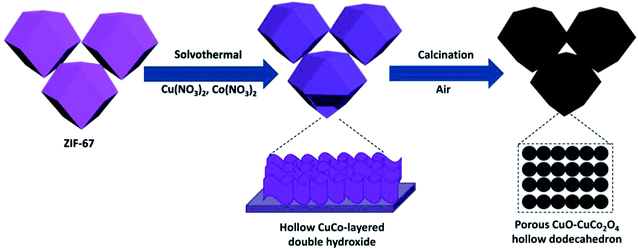
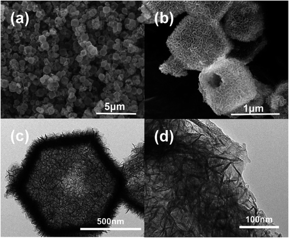
As depicted in Fig. 1, dodecahedral ZIF-67 nanoparticles were first synthesized and further used as a self-sacrificing template to prepare CuCo layered dihydroxides with hollow dodecahedron morphology. After calcination at 400 °C with a heating rate of 1 °C min−1 in air, hollow CuO–CuCo2O4 dodecahedron with hierarchical porous structure was fabricated.The SEM and TEM images of ZIF-67 particles exhibit a uniform particle size of ∼700 nm and a solid dodecahedral structure, as given in Fig. S1.† The XRD pattern of the prepared ZIF-67 demonstrates excellent crystallinity and consistency with the simulated pattern (Fig. S2†). Due to the hydrolysis of Cu(NO3)2 and Co(NO3)2 in anhydrous methanol under solvothermal conditions, Cu–Co hydroxide has been formed due to the co-precipitation of Co3+ ions released by slowly dissolved ZIF-67 and Cu2+/Co3+ ions in the solvent.23 As revealed by SEM and TEM images (Fig. 2), ZIF-67 derived flower-like Cu–Co hydroxide precursor, assembled by ultrathin nanosheets, presents a hollow structure and maintains the dodecahedral morphology. Interestingly, there are one or more large openings on the surface of each Cu–Co hydroxide dodecahedron, which are supposed to facilitate the rapid diffusion of oxygen molecules and improve utilization and reaction rate of the internal surface.24,25
After calcination in air, Cu–Co hydroxide has been transformed into CuO–CuCo2O4 composite. As shown in Fig. 3a, XRD patterns demonstrate the presence of cubic CuCo2O4 (JCPDS no. 76-1887) and hexagonal CuO (JCPDS no. 43-1003). SEM images (Fig. 3b and S3a†) reveal that CuO–CuCo2O4 composites maintained the hollow dodecahedral structure with a small number of surface openings, which exhibited a decrease in size (∼500 nm) after calcination. TEM images (Fig. 3c) further confirmed the hollow-porous structure of CuO–CuCo2O4 composites and exhibited that the surface nanosheets are actually comprised of nanocrystals, with an average diameter of ∼10 nm (inset in Fig. 3c). The N2 adsorption–desorption isotherms of CuO–CuCo2O4 composites present type-IV curves, with a distinct H3-type hysteresis loop in the middle-to-high pressure region, which confirms the presence of mesopores. The porous CuO–CuCo2O4 composites render a high surface area of 124 m2 g−1, with the main pore size of 3–12 nm (Fig. S4†).
 | ||
| Fig. 3 Materials characterization: (a) XRD pattern, (b) SEM image, (c) TEM image, (d) HRTEM image and (e) elemental maps of CuO–CuCo2O4 composites. | ||
Fig. 3d presents the HRTEM image of CuO–CuCo2O4 composite, where the lattice spacing of 0.25 and 0.30 nm belongs to (400) and (422) diffraction planes of CuCo2O4, respectively, and 0.28 nm represents the (112) plane of CuO. One should note that these observations are consistent with XRD results. The selected area electron diffraction (SAED, Fig. S3b†) pattern also confirms the polycrystalline feature of the CuO/CuCo2O4 composite. Furthermore, the elemental mapping results (Fig. 3e) indicate the uniform distribution of Cu, Co, and O in CuO–CuCo2O4 composite. The contrast in element distribution between the edge and the center also confirms the hollow structure and the existence of few large surface openings in CuO–CuCo2O4 dodecahedron.
Fig. 4a presents the wide-range XPS spectrum of CuO–CuCo2O4 composites, indicating the presence of Cu, Co, and O elements.15 The high-resolution XPS spectrum of Cu 2p is depicted in Fig. 4b, revealing the co-existence of Cu+ and Cu2+ ions.15,26 The Cu 2p3/2 spectrum consists of two peaks at 932.7 and 935.3 eV, corresponding to tetrahedral Cu+ and Cu2+ ions, respectively, and one main peak at 933.9 eV, which can be assigned to octahedral Cu2+.26,27 Moreover, the binding energies of 940.8 and 943.3 eV in the Cu 2p spectrum correspond to the satellites of divalent Cu.26,27 Furthermore, both peaks of Co 2p3/2 spectrum (Fig. 4c) can be fitted with two spin–orbit doublets at the binding energies of 779.2 and 780.4 eV, corresponding to the octahedral Co3+ and tetrahedral Co2+ ions, respectively.15,27 The peaks at 781.8 and 789.1 eV can be ascribed to the satellites of Co2+ ions.27 The peak of Co 2p1/2 spectrum can be decomposed into two peaks, centered at 794.3 and 795.8 eV, corresponding to octahedral Co3+ and tetrahedral Co2+ ions, respectively.27,28 In O 1s spectrum (Fig. 4d), the binding energy of 529.4 eV belongs to lattice oxygen (O2−) and the peak at 531.1 eV represents the defects, chemisorbed oxygen and coordinated lattice oxygen.15,26 These results reveal the existence of abundant surface valence states and defects, which can improve the intrinsic catalytic activity of the CuO–CuCo2O4 composite.
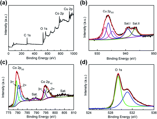 | ||
| Fig. 4 Materials characterization: XPS spectra of CuO–CuCo2O4: (a) full spectrum, high-resolution XPS spectrum of (b) Cu 2p, (c) Co 2p, and (d) O 1s. | ||
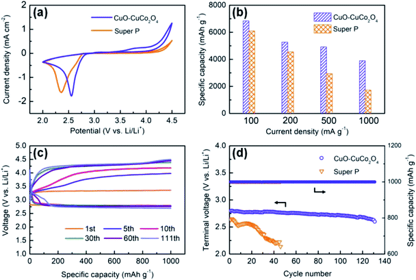
To evaluate the electrochemical performance of CuO–CuCo2O4 composites, the LOBs with CuO–CuCo2O4 composite and pure Super P cathodes are fabricated and evaluated by using cyclic voltammetry (CV) and galvanostatic charge/discharge tests. Fig. 5a presents the CV curves of CuO–CuCo2O4 composites and pure Super P cathodes. It can be readily observed that CuO–CuCo2O4 composites exhibited a higher reduction peak potential of 2.55 V and a lower oxidation peak potential of 3.75 V. Moreover, the reduction and oxidation current densities of the CuO–CuCo2O4-based LOBs were larger than the pure Super P-based LOBs, which indicates the superior catalytic activity of CuO–CuCo2O4 for ORR and OER.22,27 The abundant octahedral Cu2+ ions in CuO–CuCo2O4 composite, as illustrated in Fig. 4b, may explain its excellent OER activity. It has been reported that the octahedral divalent ions render superior catalytic activity toward OER than the tetrahedral ions.15,26
Hence, the CuO–CuCo2O4 composite is a promising air electrode material in LOBs owing to its excellent catalytic activity towards ORR and OER, hierarchically arranged hollow porous architecture, high surface area and large pore volume. Such a structure is not only beneficial to expand active electrochemical sites and promote the electrolyte diffusion but also accommodates more discharge products when used as an air electrode material in LOBs. Fig. S5a† presents the initial full discharge/charge profiles of CuO–CuCo2O4- and pure Super P-based LOBs at 100 mA g−1. The CuO–CuCo2O4 composite delivered an initial discharge capacity of 6844 mA h g−1 and presented a stable discharge plateau at ∼2.79 V, whereas the pure Super P cathode delivered an initial capacity of 6054 mA h g−1 and exhibited a potential plateau at 2.65 V. Furthermore, the discharge/charge overpotential of the CuO–CuCo2O4 cathode has been significantly reduced to 1.15 V, which confirms the superior catalytic activity of CuO–CuCo2O4 composite towards ORR and OER in non-aqueous LOBs. We also tested the full discharge/charge performance of pure Super P based- and CuO–CuCo2O4 based-electrodes under a voltage-limiting mode within 2.2–4.4 V without capacity limitation, as shown in Fig. S5b and c,† respectively. Due to the good reversibility, the CuO–CuCo2O4 based-electrode still delivered a high capacity over 1000 mA h g−1 after 7 cycles under a current density of 500 mA g−1 whereas the Super P based-electrode only show 1 cycles. The rate capability of LOBs, with two different cathodes, has been evaluated by carrying out discharge/charge testing at different current densities, ranging from 100 to 1000 mA g−1 (Fig. 5b). Although the discharge capacity of both cathodes decreased with increasing current density because of enhanced polarization, the discharge capacity of CuO–CuCo2O4 cathode remained higher than the discharge capacity of Super P cathode. At the current density of 200, 500 and 1000 mA g−1, the CuO–CuCo2O4 composite cathode exhibited the discharge capacity of 5276, 4917 and 3903 mA h g−1, whereas the Super P cathode delivered the capacity of 4556, 2943 and 1731 mA h g−1, respectively. A comparative chart of average discharge specific capacities with error-bar was also provided to avoid the measurement errors, as given in Fig. S6.† Although the specific capacities vary from one to another when using coin-type cells, the trend that the synthesized catalyst can increase the discharge capacities is obvious and affirmatory. Moreover, it can be readily observed that the CuO–CuCo2O4 composite cathode retained 74% of the initial capacity when the current density was enhanced from 200 to 1000 mA g−1. However, the Super P cathode only retained 38% of the initial capacity with increasing current density, which confirms the superior rate performance of CuO–CuCo2O4 composite cathode.
Furthermore, the cyclic performance, which is a key performance criterion in LOBs, can be remarkably improved by employing a high-efficient catalyst. Herein, the cyclic performance of CuO–CuCo2O4 composite cathode and Super P cathode has been investigated by measuring the restricted capacity of 1000 mA h g−1 at 400 mA g−1 in the voltage range of 2.2 to 4.5 V, as shown in Fig. 5c and d. During the first cycling process, CuO–CuCo2O4 composite showed a high discharge potential of ∼2.80 V, which is obviously higher than the Super P cathode (∼2.65 V vs. Li/Li+). Moreover, CuO–CuCo2O4 composite cathode demonstrated a low charging potential of ∼3.34 V, which is 0.54 V higher than the discharge voltage and indicates the superior OER catalytic activity. The CuO–CuCo2O4 composite and Super P cathodes exhibited a cycling efficiency of 83.9% and 61.0% (discharge platform voltage/charge platform voltage), respectively. During the initial 10 cycles, the charging potential increased with increasing ohmic resistance due to the formation of solid electrolyte interface (SEI) film on the lithium metal and the partial deactivation of the active sites on the cathode surface.5,29
Furthermore, after 111 charge/discharge cycles, CuO–CuCo2O4 composite cathode maintained a high terminal discharge voltage of 2.69 V under the limited charge voltage of 4.5 V. On the other hand, the Super P cathode only remained operational for 46 charge/discharge cycles and the terminal discharge voltage quickly decreased to 2.14 V, as given in Fig. S5d.† The electrochemical performance of CuCo2O4 and other MOF-derived transition metal oxides in Li–O2 batteries has been summarized in Table S1.† It can be readily observed that the as-synthesized CuO–CuCo2O4 composite delivered superior electrocatalytic performance than the previously reported MOF-derived transition metal oxides. The outstanding electrocatalytic performance of CuO–CuCo2O4 composite can be ascribed to the synergetic effect of intrinsic catalytic activity and the hollow porous dodecahedral architecture.
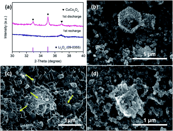
In addition, the ex situ XRD and SEM analysis were carried out to observe the structural and morphological changes in CuO–CuCo2O4 composite cathode during charging/discharging. Fig. 6a shows the coexistence of CuCo2O4 and Li2O2 after the 1st discharge state, which indicates that Li2O2 is the dominant product in the ORR process. However, the Li2O2 is fully decomposed after charging, which indicates the excellent reversibility of the discharge product during the charge–discharge process. Furthermore, the ex situ SEM images (Fig. 6c) show that the surface of CuO–CuCo2O4 cathode is entirely covered by insoluble flake-like reaction products after the discharge process, which is consistent with the reported morphology of Li2O2 discharge product.30,31 However, the flake-like reaction product has been completely removed from the cathode surface after the charge process, as shown in Fig. 6d, preserving the initial cathode morphology (Fig. 6b). These observations confirm the excellent reversibility of the CuO–CuCo2O4 composite cathode.
4. Conclusions
In all, we have proved the successful synthesis of MOF-derived CuO–CuCo2O4 composite by solvothermal method and used as a cathode catalyst in rechargeable LOBs. Owing to the unique morphology of ZIF-67 template, the as-synthesized CuO–CuCo2O4 composite rendered dodecahedron morphology with hollow porous structure. The hierarchically constructed meso- and macro-pores provided abundant electrocatalytic active sites and large surface area, which facilitated the charge transfer kinetics, resulted in efficient transportation of reactants/electrons and accommodated the discharge products, i.e., Li2O2. Overall, the CuO–CuCo2O4 composite resulted in significantly enhanced electrocatalytic activity for ORR and OER in non-aqueous LOBs. As a result, the CuO–CuCo2O4 composite cathode delivered a high discharge capacity of 6844 mA h g−1 at 100 mA g−1 and stable cycle life up to 111 cycles. The flake-like Li2O2 discharge product and the excellent reversibility of the CuO–CuCo2O4 based air electrode were also revealed by ex situ XRD and SEM characterizations. These results reveal that MOF-derived CuO–CuCo2O4 composite is a promising cathode catalyst for high-performance and long-life LOBs.Conflicts of interest
There are no conflicts to declare.Acknowledgements
This work is supported by National Natural Science Foundation of China (21506012 and 51802018), China Postdoctoral Science Foundation (no. 2017M620642) and Analysis & Testing Center (Beijing Institute of Technology).References
- K. M. Abraham, J. Phys. Chem. Lett., 2015, 6, 830–844 CrossRef CAS PubMed
.
- P. G. Bruce, S. A. Freunberger, L. J. Hardwick and J. M. Tarascon, Nat. Mater., 2011, 11, 19–29 CrossRef PubMed
.
- N. Akhtar and W. Akhtar, Int. J. Energy Res., 2015, 39, 303–316 CrossRef CAS
.
- T. Vegge, J. M. Garcia-Lastra and D. J. Siegel, Curr. Opin. Electrochem., 2017, 6, 100–107 CrossRef CAS
.
- H. Wu, W. Sun, Y. Wang, F. Wang, J. Liu, X. Yue, Z. Wang, J. Qiao, D. W. Rooney and K. Sun, ACS Appl. Mater. Interfaces, 2017, 9, 12355–12365 CrossRef CAS PubMed
.
- A. Chamaani, M. Safa, N. Chawla and B. El-Zahab, ACS Appl. Mater. Interfaces, 2017, 9, 33819–33826 CrossRef CAS PubMed
.
- J. Ren, Z. Huang, P. K. Kalambate, Y. Shen and Y. Huang, RSC Adv., 2018, 8, 28496–28502 RSC
.
- R. Bi, G. Liu, C. Zeng, X. Wang, L. Zhang and S. Z. Qiao, Small, 2019, 15, e1804958 CrossRef PubMed
.
- N. Chawla, A. Chamaani, M. Safa and B. El-Zahab, J. Electrochem. Soc., 2016, 164, A6303–A6307 CrossRef
.
- J. Gao, X. Cai, J. Wang, M. Hou, L. Lai and L. Zhang, Chem. Eng. J., 2018, 352, 972–995 CrossRef CAS
.
- H. Dong, P. Tang, S. Zhang, X. Xiao, C. Jin, Y. Gao, Y. Yin, B. Li and S. Yang, RSC Adv., 2018, 8, 3357–3363 RSC
.
- S. Liu, C. Wang, S. Dong, H. Hou, B. Wang, X. Wang, X. Chen and G. Cui, RSC Adv., 2018, 8, 27973–27978 RSC
.
- Y. Chen, D. Cao, S. Zhang, F. Yu and Y. Wu, Batteries Supercaps, 2019, 2, 1–13 CrossRef
.
- T. Grewe, X. Deng, C. Weidenthaler, F. Schüth and H. Tüysüz, Chem. Mater., 2013, 25, 4926–4935 CrossRef CAS
.
- H. T. Wu, W. Sun, J. R. Shen, Z. Mao, H. Wang, H. Q. Cai, Z. H. Wang and K. N. Sun, ACS Sustainable Chem. Eng., 2018, 6, 15180–15190 CrossRef CAS
.
- S. Xu, Y. Yao, Y. Guo, X. Zeng, S. D. Lacey, H. Song, C. Chen, Y. Li, J. Dai, Y. Wang, Y. Chen, B. Liu, K. Fu, K. Amine, J. Lu and L. Hu, Adv. Mater., 2018, 30, 1704907 CrossRef PubMed
.
- Y. Li, Y. Xu, W. Yang, W. Shen, H. Xue and H. Pang, Small, 2018, 14, e1704435 CrossRef PubMed
.
- M. Yuan, R. Wang, W. Fu, L. Lin, Z. Sun, X. Long, S. Zhang, C. Nan, G. Sun, H. Li and S. Ma, ACS Appl. Mater. Interfaces, 2019, 11, 11403–11413 CrossRef CAS PubMed
.
- C. Deng and D. W. Wang, Batteries Supercaps, 2019, 2, 290–310 CrossRef CAS
.
- J. Zhang, L. Wang, L. Xu, X. Ge, X. Zhao, M. Lai, Z. Liu and W. Chen, Nanoscale, 2015, 7, 720–726 RSC
.
- W. Yin, Y. Shen, F. Zou, X. Hu, B. Chi and Y. Huang, ACS Appl. Mater. Interfaces, 2015, 7, 4947–4954 CrossRef CAS PubMed
.
- A. Li, X. Zhang, Z. Xie, Z. Chang, Z. Zhou and X. H. Bu, Inorg. Chem., 2018, 57, 14476–14479 CrossRef CAS PubMed
.
- C. Sun, J. Yang, X. Rui, W. Zhang, Q. Yan, P. Chen, F. Huo, W. Huang and X. Dong, J. Mater. Chem. A, 2015, 3, 8483–8488 RSC
.
- S. Xu, Y. Yao, Y. Guo, X. Zeng, S. D. Lacey, H. Song, C. Chen, Y. Li, J. Dai, Y. Wang, Y. Chen, B. Liu, K. Fu, K. Amine, J. Lu and L. Hu, Adv. Mater., 2018, 30, 1704907 CrossRef PubMed
.
- H. Kim, H. Lee, M. Kim, Y. Bae, W. Baek, K. Park, S. Park, T. Kim, H. Kwon, W. Choi, K. Kang, S. Kwon and D. Im, Carbon, 2017, 117, 454–461 CrossRef CAS
.
- A. La RosaToro, R. Berenguer, C. Quijada, F. Montilla, E. Morallón and J. L. Vázquez, J. Phys. Chem. B, 2006, 110, 24021–24029 CrossRef CAS PubMed
.
- W. Sun, Y. Wang, H. T. Wu, Z. H. Wang, D. Rooney and K. N. Sun, Chem. Commun., 2017, 53, 8711–8714 RSC
.
- P. F. Li, W. Sun, Q. Yu, P. Yang, J. S. Qiao, Z. H. Wang, D. Rooney and K. N. Sun, Solid State Ionics, 2016, 289, 17–22 CrossRef CAS
.
- Z. Sadighi, J. Liu, F. Ciucci and J. K. Kim, Nanoscale, 2018, 10, 15588–15599 RSC
.
- B. Sun, X. Huang, S. Chen, P. Munroe and G. Wang, Nano Lett., 2014, 14, 3145–3152 CrossRef CAS PubMed
.
- J. Cheng, M. Zhang, Y. Jiang, L. Zou, Y. Gong, B. Chi, J. Pu and L. Jian, Electrochim. Acta, 2016, 191, 106–115 CrossRef CAS
.
Footnote |
| † Electronic supplementary information (ESI) available. See DOI: 10.1039/c9ra02860a |
| This journal is © The Royal Society of Chemistry 2019 |

