 Open Access Article
EMI shielding of ABS composites filled with different temperature-treated equal-quantity charcoals
Krishna Kamal Halderab,
V. K. Sachdev *a,
Monika Tomar
 c and
Vinay Gupta
 a
a
aDepartment of Physics and Astrophysics, University of Delhi, Delhi-110007, India. E-mail: vk_sachdev@yahoo.com
bKirori Mal College, University of Delhi, Delhi-110007, India
cMiranda House, University of Delhi, Delhi-110007, India
First published on 30th July 2019
Abstract
Acrylonitrile-butadiene-styrene (ABS) composites were prepared by dry mixing equal-quantity (20 wt%) charcoals treated at different temperatures followed by hot compression. Processing parameters were kept the same. Seven samples of the same charcoal were modified for carbonization at different temperatures varying from 500 °C to 1100 °C in steps of 100 °C. Temperature treatment of charcoal crafts an increase in the conductivity of ABS composites, primarily accountable for the enhancement of shielding. The electromagnetic shielding effectiveness in the X-band (8.2–12.4 GHz) has been discovered to significantly increase for composites with ascending temperature-treated charcoals. An abrupt increase in the conductivity of ABS composites containing equal quantities of charcoal subjected to enhanced temperature treatments truly explains the effective absorption behaviour. The composite containing 1100 °C temperature-treated charcoal shows absorption-dominated SE of ∼36.8 dB at 11.6 GHz. Dielectric behaviour proclaims a decrease in dielectric loss (ε′′) with an increase in the frequency. Besides this, the increased carbonization temperatures also show increased porosity and high dielectric losses. The scanning electron microscopy studies validate the increase in the porosity of charcoals due to the increase in the treatment temperature. The results are promising for the development of custom-made shielding composites possessing equal quantities of charcoal treated at enhanced temperatures.
1. Introduction
Electronic devices have brought a revolution in society with their faster technological development. On the optimistic side these devices have made the humans life much easier, but on the pessimistic side electromagnetic (EM) interference with the sophisticated electronic devices and EM radiation exposure to human health become distressing. Electromagnetic interference (EMI) is the meddling of unwanted signals produced by one electronic device with that of the other via conducted or radiated paths, giving rise to the degradation of system or equipment performance.1,2 Thus, EM shielding of sophisticated electronic paraphernalia is inevitable. Therefore, it is desirable to identify and develop some effective shielding materials. Conventionally, metals are used as shielding materials, but this is disadvantageous because of heavy weight, poor chemical resistance, seams and difficulty in handling as a shield. Metals are now being replaced by conducting polymer composites (CPCs) for use as shielding materials.1,3–5 Polymer composites using metal nanoparticles and various compounds derived from metals as fillers are explored. Carbonyl iron-loaded polydimethylsiloxane composites have been reported to be applied in radio absorbers.6 Indeed, polymer composites have a wide range of applications. In automobile industries, the focus is on the replacement of metal alloys with high-strength polymer composites.7 The polymer composites are electrical insulators in general. To make them conducting, different types of conducting fillers such as MWCNTs, graphene, graphite, metal powder and carbon fibre have been used.5,8–13 CPCs' low cost, easy processing, as well as suitable matrices for biomolecule immobilization qualified them for the development of polyaniline-based biosensors.14 Additionally, CPCs are used for applications in field emission transistors, supercapacitors, batteries, solar cells and biomedical instruments.7,15,16 Although MWCNTs are the most explored materials as fillers because of their high aspect ratio and good conductivity, the high aspect ratio develops strong van der Waals intermolecular interactions that causes much difficulty in the uniform dispersion of MWCNTs in the polymer matrix.17 The electrical properties of various forms of carbon-based polymer composites have attracted considerable attention in many scientific applications including EMI shielding. The potential of 2D materials for microwave absorption and EMI shielding applications in the GHz frequency range18 has been reported. Reduced graphene oxide (RGO) as a filler is a good contender for EMI shielding applications at a higher temperature range.19 In one report, carbon fibre-incorporated silica composites for EMI shielding and microwave absorption applications20 are described. The conductive nature of carbon results in an enhanced EMI shielding property in carbon-filled polymer composites. These composites are broadly divided into two categories, namely, the sp2-bonded atoms having hexagonal stacking and sp3-bonded atoms of carbon having tetrahedral geometry. It is reported that carbonization, i.e. temperature treatment, changes the chemical and electrical properties of carbon-based materials.21 During the process of carbonization/temperature treatment of wood, sp2-bonded atoms are formed.22 The electrical resistivity of carbonized materials is stated to be strongly dependent on the carbonization temperature. Reports describe that carbonized wood behaves as an insulator for carbonization temperatures below 500 °C, while above 800 °C, its resistivity decreases considerably,23 exhibiting a good conductivity with the increase in the carbonization temperature up to 1800 °C.24 This feature boosts the suitability of carbon-based compounds (charcoal) as fillers in polymer composites, particularly for EMI shielding applications. Charcoal/UHMPE polymer composites have been described to show enriched mechanical properties on carbonization,25 but there is no report on the study of EMI shielding properties pertinent to the carbonization temperature of charcoal.In the present work, acrylonitrile-butadiene-styrene (ABS) polymer composites containing equal quantities of conductive charcoal carbonized at different temperatures are developed and investigated for EMI shielding applications. ABS is used as a polymer matrix. It is a thermoplastic resin copolymer of acrylonitrile, butadiene and styrene. It exhibits hard and rigid nature, good heat resistance, excellent performance at high and low temperatures, electroplatability, light-weight structure and good dimensional stability.26 It offers good impact strength and chemical resistance. It also possesses good adhesive properties and printability.27 In this research, conductive ABS polymer composites using equal amounts of charcoal carbonized at different temperatures were developed. The carbonization temperature of ∼800 °C improves the Young's modulus of charcoal,28 which enhances the mechanical strength of the composites.25,29 The process of additional carbonization of charcoal through temperature treatments is a noteworthy approach to modify the electrical conductivity and morphology of the composite that makes the charcoal-customized conductive filler for EMI shielding applications.
2. Experimental
ABS-92 was procured from Lanxess India in granular form and pulverized to particle size <400 micron. Hard wood commercial charcoal was selected because of its ability for additional carbonization through temperature treatments. Further carbonization of charcoal was achieved in a N2 atmosphere using a Tubular furnace procured from Jupiter Engineering Works India. Desired temperatures in the range of 500–1100 °C were regulated within the accuracy of ±1% for 1 hour. Seven temperature-treated charcoal samples correspondingly at 500, 600, 700, 800, 900, 1000 and 1100 °C were obtained. Each charcoal sample was crushed to powder and its 20 wt% representative fixed quantity was mixed into the ABS powder by means of a magnetic stirrer for 200 minutes. Herein, 20 wt% quantity of the charcoal was chosen since the conductivity percolation threshold of the charcoal without temperature treatment in ABS composites is ∼10 wt% and the probability of some good first-hand information is more. The resulting mixture was heated at 115 °C for 15 minutes in a rectangular X-band wave guide-shaped pressure mould, brought back to a lower temperature of 90 °C and subsequently compressed at a constant pressure of 75 MPa for 15 minutes. Three composite pellets were prepared for each temperature-treated charcoal. The electrical conductivity (σ) values of composites were determined using a Keithley 4200 system-210 V/100 mA, 0.1 fA resolution setup, while EMI Shielding effectiveness (SE) evaluations were performed using an Agilent vector network analyser (VNA), model N5230C PNA-L 10 MHz to 40 GHz in the X-band frequency range, the same as earlier.30 S-parameters were measured in the same range. For morphological studies of composites, a ZEISS FESEM was used. The ASTM D792 method was employed for the assessment of density of each carbonized charcoal. For XRD, Rigaku Ultima-IV was used, and FTIR spectroscopy of charcoal was performed on a PerkinElmer (Frontier).3. Results and discussion
3.1 XRD studies
Fig. 1 represents the XRD patterns for treated charcoals at carbonization temperatures of 500 °C, 800 °C and 1100 °C. For each carbonization temperature, two diffraction peaks were obtained at angles (2θ) of 23.38° and 43.18°.31,32 The peak at 43.18° becomes prominent with the increasing carbonization temperature. In this whole XRD pattern, no sharp peak is noticed, which implies that the carbonized charcoal is amorphous in nature.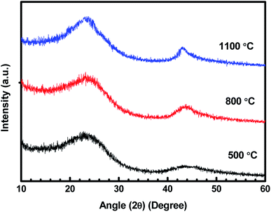 | ||
| Fig. 1 XRD patterns of carbonized charcoals at 500 °C, 800 °C and 1100 °C carbonization temperatures. | ||
3.2 FTIR studies
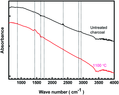
The FTIR spectra of the untreated charcoal and the 1100 °C temperature-treated carbonized charcoal are displayed in Fig. 2. The black colour of both untreated and treated charcoals indicates higher absorption of visible spectra. Consequently, the FTIR spectra have not been clearly resolved. The peak at 880 cm−1 in the spectrum of 1100 °C temperature-treated carbonized charcoal represents the aromatic outer mode of vibration, which is absent in the spectrum of untreated charcoal.23 The C![[double bond, length as m-dash]](https://www.rsc.org/images/entities/char_e001.gif) C vibrational band represented by 1450 cm−1 and 1630 cm−1 appeared after the carbonization of charcoal.33 The peak at 1450 cm−1 could be attributed to the C–H deformation in lignin and carbohydrate.34 The peak corresponding to the –C
C vibrational band represented by 1450 cm−1 and 1630 cm−1 appeared after the carbonization of charcoal.33 The peak at 1450 cm−1 could be attributed to the C–H deformation in lignin and carbohydrate.34 The peak corresponding to the –C![[double bond, length as m-dash]](https://www.rsc.org/images/entities/char_e001.gif) O functional group has been observed at 1750 cm−1.35 The peak at 2340 cm−1 in the spectrum of untreated charcoal may be assigned to the dissolved CO2 present in the untreated charcoal,36 which disappears after carbonization at higher temperatures (1100 °C). The peaks appearing between 2800–3000 cm−1 have been assigned to CH3, CH2 and CH functional groups.35 A decrease in the intensity at higher carbonization temperatures is observed.
O functional group has been observed at 1750 cm−1.35 The peak at 2340 cm−1 in the spectrum of untreated charcoal may be assigned to the dissolved CO2 present in the untreated charcoal,36 which disappears after carbonization at higher temperatures (1100 °C). The peaks appearing between 2800–3000 cm−1 have been assigned to CH3, CH2 and CH functional groups.35 A decrease in the intensity at higher carbonization temperatures is observed.
3.3 Conductivity
The variation in the log(σ) values as a function of charcoal carbonization temperature for seven ABS–charcoal composite samples each containing 20 wt% of charcoal carbonized at different temperatures between 500 and 1100 °C in steps of 100 °C is shown in Fig. 3. Herein, σ is the mean value of three samples of each composite corresponding to their carbonization temperature shown on the log scale because of large variations in σ from 3.56 × 10⁻⁵ S cm−1 to 4.81 S cm−1 over the temperature range of 500–1100 °C. The maximum departure of σ from the mean values is ±0.24 S cm−1 for the largest value of σ (at 1100 °C).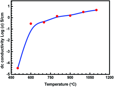 | ||
| Fig. 3 Variation in dc conductivity (σ) of ABS charcoal composites with the carbonization temperature. | ||
It may be seen that the σ value of the composites increases sharply from semiconducting to conducting range, 3.56 × 10⁻⁵ S cm−1 to 2.99 × 10⁻¹ S cm−1 related to charcoals treated at 500 °C and 600 °C. Beyond that, σ tends towards saturation with an increase in the carbonization temperature. An almost flat value of 4.81 S cm−1 is obtained for the composite having charcoal carbonized at 1100 °C temperature. The increase in the carbonization temperature decreases the volatile stuffing within the charcoal, thereby increasing the content of carbon in the charcoal and forming a more graphitised carbon structure.37,38 EDAX performed on 500 °C, 900 °C and 1100 °C temperature-treated charcoals confirm the increase in the carbon content from 89.31 wt% with 95.64 at% in charcoal treated at 500 °C to 91.85 wt% with 96.73 at% in charcoal treated at 1100 °C through 91.62 wt% with 96.62 at% in charcoal treated at 900 °C. The saturating carbon content with the increase in temperature authenticates the conductivity behaviour in this range of temperature. Hydrogen would be released due to the breakage of C–H bonds. Initially up to 600 °C, the removal of volatile materials is likely to be the largest, and beyond that, the removal of volatile substance decreases. The breakage of C–H bonds produces free electrons, responsible for the increase in the conductivity of charcoal. Moreover, increasing the carbonization temperature increases the C/H ratio, which leads to a rise in the degree of aromatization of charcoal.38 The aromatization of charcoal would lead to a decrease in the resistivity since the aromatic nuclei have low energy gap and high σ values.38,39 Here, in these charcoal/ABS composites, mainly conduction and hopping are the two possible ways of charge transportation through a network of conducting pathways. The increasing electrical conductivity of the carbonized charcoal at elevated carbonization temperatures can be explained assuming the formation of more graphitised carbon structures37,38 and the migration of electrons via conduction and hopping through the defects and interface between the disorder of the graphitised carbon structure.20,40,41 The increase in the carbonization temperature produces an increase in the graphitised carbon concentration, which results in a decrease in the distance between graphitised carbon particles, responsible for the rising level of conductivity of carbonized charcoals. The temperature-treated charcoal with improved conductivity forms a conducting network within the polymer composites, which converts the insulating polymer into semiconducting or conducting polymer composites, resulting in a higher electrical conductivity.42 The porosity and surface area of temperature-treated charcoals are anticipated to increase with temperature, improving the surface chemistry of charcoals.
3.4 Density
Seven temperature-treated charcoals obtained correspondingly at 500, 600, 700, 800, 900, 1000 and 1100 °C were put to density measurements. The density of each carbonized charcoal has been measured using the ASTM D792 method through the equation ωa/(ωa − ωl), where ωa and ωl represent the weight of the sample in air and distilled water, respectively. The digital balance used for weighing was accurate to 0.0001 g. The density of the carbonized charcoals is noticed to decrease up to 800 °C remarkably. Above 800 °C, the fall in the density of charcoals is in a very slow pace. The density of the untreated charcoal is ∼0.705 g cm−3, whereas the density of 800 °C temperature-treated charcoal is ∼0.511 g cm−3. The density of 1100 °C temperature-treated carbonized charcoal is 0.474 g cm−3 because up to 800 °C most of the volatile substances in the charcoal got evaporated.3.5 Morphological studies
Pristine ABS has a featureless morphology. Undoubtedly, the incorporation of charcoals into its matrix would change the morphology and microstructure of composites. However, it is important to see how the same charcoal in equal amounts but treated at different temperatures behaves in the ABS matrix. FESEM studies reveal the structural changes in ABS composites containing charcoals treated at increasing carbonization temperatures. Fig. 4(a–d) are the FESEM micrographs of cryo-fractured pellets of ABS composites prepared with charcoals treated at 500, 700, 900 and 1100 °C temperatures. The presence of discrete and small-sized conducting composite particles noticeable in Fig. 4(a) may be responsible for the low value of σ, whereas large cohesive conducting composite particles with pores shown in Fig. 4(b–d) endorse a high σ value. The removal of volatile materials and the increase in the C/H ratio at elevated carbonization temperatures of charcoals have probably made it possible to form chunks of conducting composites in ABS composites. The increase in the carbonization temperature increases the surface area and porosity of charcoals,43 leading to the formation of foam-like structures. During fabrication of composites, the charcoal powder get coated on to the ABS particles and on pressure compaction localized in to the interfacial positions. Pressure compaction enhances the closeness between the particles and thereby the σ value.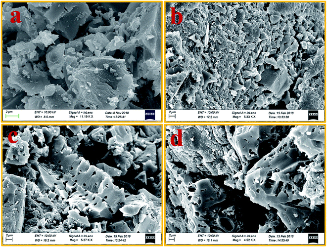 | ||
| Fig. 4 (a–d) FESEM images of 500 °C, 700 °C, 900 °C and 1100 °C temperature-treated charcoals/ABS composites, respectively. | ||
3.6 Dielectric studies
The dielectric properties of a polymer composite mainly depend on the permittivity, conductivity, and relative volume fraction of constituents in the composite in addition to the morphology of the system.44 The dielectric constant depends on the porosity and grain size of the filler. With the increase in the pore and grain sizes, the dielectric constant decreases.45 As the carbonization temperature increases, the pore size of the charcoal increases and the density decreases. The dielectric constant is recognised as ε = ε′ + jε′′, where ε′ and ε′′ are the real and imaginary parts of the dielectric constant, respectively.46,47 Percolating composites containing conducting fillers display the noteworthy permittivity due to interfacial polarization, which appears at the interface of different materials.48,49 The mobile charges in different parts of composites are obstructed at the interface consisting of two materials of different permittivities and conductivities. These bunged up charges are incapable to discharge freely amass at an interface and give rise to an overall field distortion. This results in an increase in the capacitance of the system as a result of high interfacial polarization.44 The values for ε′ and ε′′ for charcoal/ABS pellets are evaluated using the Nicholson–Ross–Weir method from S-parameter measurements using a vector network analyser as described earlier.42Using free electron theory, ε′′ can be written as,20,50
 | (1) |
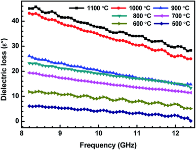 | ||
| Fig. 5 Variation of dielectric loss (ε′′) of ABS charcoal composites with the frequency for different carbonization temperatures. | ||
| Carbonization temperature (°C) | ε′ | ε′′ | A | R | T | SERef | SEAbs | SETotal |
|---|---|---|---|---|---|---|---|---|
| 500 | 13.13 | 6.11 | 49.82 | 39.63 | 10.55 | 2.19 | 7.58 | 9.77 |
| 600 | 14.77 | 11.80 | 49.57 | 41.21 | 9.22 | 2.31 | 9.11 | 11.42 |
| 700 | 13.80 | 19.38 | 47.25 | 51.19 | 1.56 | 3.11 | 14.96 | 18.07 |
| 800 | 13.69 | 23.24 | 46.76 | 52.21 | 1.02 | 3.30 | 16.70 | 20.00 |
| 900 | 18.25 | 26.10 | 35.10 | 64.55 | 0.33 | 4.51 | 20.23 | 24.74 |
| 1000 | 15.99 | 43.16 | 36.03 | 63.80 | 0.16 | 4.41 | 23.46 | 27.87 |
| 1100 | 14.75 | 45.06 | 35.27 | 64.69 | 0.02 | 4.26 | 31.85 | 36.11 |
Fig. 6 represents the variation of loss tan![[thin space (1/6-em)]](https://www.rsc.org/images/entities/char_2009.gif) δ with the carbonization temperature of charcoals in ABS–carbonized charcoal composites, calculated using tan
δ with the carbonization temperature of charcoals in ABS–carbonized charcoal composites, calculated using tan![[thin space (1/6-em)]](https://www.rsc.org/images/entities/char_2009.gif) δ = ε′′/ε′. Dielectric loss tan
δ = ε′′/ε′. Dielectric loss tan![[thin space (1/6-em)]](https://www.rsc.org/images/entities/char_2009.gif) δ is the dissipation of energy. Different physical phenomena like electrical conduction, dielectric relaxation and loss from non-linear processes contribute to loss tan
δ is the dissipation of energy. Different physical phenomena like electrical conduction, dielectric relaxation and loss from non-linear processes contribute to loss tan![[thin space (1/6-em)]](https://www.rsc.org/images/entities/char_2009.gif) δ.51 In Table 1, the value of ε′′ increases with the increasing carbonization temperature, which can be explained using eqn (1). It can be seen that the electrical conductivity plays an important role in developing ε′′. The values of ε′ remain almost constant for all the carbonization temperature as the quantity of different temperature treated charcoals in composites is equal. Therefore, tan
δ.51 In Table 1, the value of ε′′ increases with the increasing carbonization temperature, which can be explained using eqn (1). It can be seen that the electrical conductivity plays an important role in developing ε′′. The values of ε′ remain almost constant for all the carbonization temperature as the quantity of different temperature treated charcoals in composites is equal. Therefore, tan![[thin space (1/6-em)]](https://www.rsc.org/images/entities/char_2009.gif) δ increases with the rising carbonization temperature since the rise in carbonization temperature raises the conductivity of the charcoal. This outcome reveals that the ABS composites become more lossy with the growing conductivity of charcoal particles.
δ increases with the rising carbonization temperature since the rise in carbonization temperature raises the conductivity of the charcoal. This outcome reveals that the ABS composites become more lossy with the growing conductivity of charcoal particles.
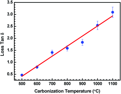 | ||
Fig. 6 Variation in tan![[thin space (1/6-em)]](https://www.rsc.org/images/entities/char_2009.gif) δ of ABS charcoal composites at a frequency of 8.2 GHz for different carbonization temperatures. δ of ABS charcoal composites at a frequency of 8.2 GHz for different carbonization temperatures. | ||
3.7 Shielding measurements
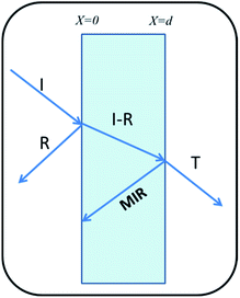
Shielding is the attenuation of electromagnetic (EM) signals after a blockade is introduced between the radiation source and the object to be protected. Fig. 7 illustrates the schematic of shielding mechanisms.There are three mechanisms of EMI shielding: reflection, absorption and Multiple Internal Reflection (MIR). Reflection is a surface phenomenon as it occurs at the interface of two materials, whereas absorption is a volume phenomenon and its contribution increases with the increase in the shield thickness. Multiple reflection is significant only in the case of thin shields and can be neglected for thick shields when loss due to absorption SEAbs becomes >10 dB,52
| SETotal = SEAbs + SERef + SEMIR | (2) |
The SE values are determined using reflectance (R), transmittance (T) and absorbance (A), which refer to the fraction of power incident (PI), reflected (PR), transmitted (PT) and absorbed (PA) respectively by the shield, defined as:
 | (3) |
In terms of S-parameters
 | (4) |
 | (5) |
SERef and SEAbs are evaluated using the following relations:
| SERef(dB) = 10 × log10(1 − R) | (6) |
 | (7) |
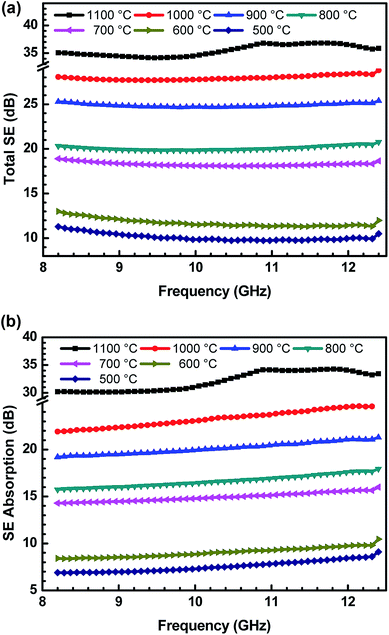
In the present work, the SE values are determined by measuring scattering parameters S11/S22 and S12/S21, obtained using two ports of vector network analyser.30 S-parameters are stately with a regular fixed interval of 84 MHz in the frequency range of 8.2–12.4 GHz. The uncertainties in SE measurements are between 0.07 and 1 dB, using a VNA uncertainty calculator.42 Fig. 8(a and b) show the variation of total SE and evaluated value of SE absorption as a function of frequency for various ABS–charcoal composites having charcoals carbonized at different temperatures.
Total SE and SE absorption, both are seen to be increasing with the increase in the treatment temperature of charcoals in the composites. Further, it may be seen that as a function of frequency, total SE and absorption SE both remain almost constant in the entire frequency range for all the samples. The evaluated value SE reflection is observed to be almost the same since the quantity of charcoals is the same in all the ABS composites. For ABS–charcoal composites having charcoal treated at 500 °C, total SE is ∼9.9 dB at 11.6 GHz frequency, which increases to ∼36.8 dB in the composite charcoal treated at 1100 °C. Broadly, the increase in total SE is due to the increase in the conductivity of composites. Basically, ABS is an insulator and the charcoal is accountable for the increase in the electrical conductivity of the ABS–charcoal. As the carbonization temperature increases, the conductivity of charcoal increases due to the aromatization of charcoal, breakage of C–H bonds and reduction of volatile substances.38 During the fabrication of composites, the charcoal powder is coated on the ABS particles and the probability of its migration to interfacial positions may not be ruled out. Pressure compaction enhances the closeness between composite particles leading to the formation of conducting channels, thus providing adequate electrical conduction. The porous structure and increasing electrically conducting nature of ABS–charcoal composites with the increasing carbonization temperature observed in FESEM micrographs (Fig. 4) corroborate the increase in total SE with enhanced carbonization temperature-treated charcoals in ABS composites.
Earlier, the SE performance of composites in the same ABS matrix with nano-fibril MWCNTs and laminar graphite was studied.42 The maximum value of total SE ∼40 dB with small quantity (5 wt%) of MWCNTs in ABS achieved was comparatively higher because of MWCNTs' high aspect ratio and good conductivity, but high cost and difficulty in the processing of MWCNTs in a polymer matrix hamper its commercial applications.
Reflection and absorption are correspondingly the surface and volume phenomena for primary EMI shielding mechanism. Both are known to increase with the increase in the conductivity of polymer composites. As reflection (R) occurs before absorption (A), the intensity of the EM wave that enters inside the shield after primary reflection is based on the quantity (1 − R). Therefore, in order to get a true picture, the absorption (A) can be normalized using the factor (1 − R) to yield effective absorbance (Aeff) using the following relation,53,54
 | (8) |
Fig. 9 shows the variation in Aeff of ABS charcoal composites at a frequency of 8.2 GHz for different carbonization temperatures. From the previous knowledge,42 the Aeff values have been extracted from S11/S12 parameters. The expression for SEAbs can be written as,55
 | (9) |
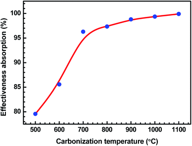 | ||
| Fig. 9 Variation in Aeff of ABS charcoal composites at a frequency of 8.2 GHz for different carbonization temperatures. | ||
Fig. 10 demonstrates the behaviour of total SE, SE absorption and SE reflection of ABS–charcoal composites as a function of carbonization temperature of the charcoal at a certain representational frequency of 11.6 GHz.
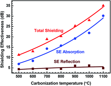 | ||
| Fig. 10 Variation of total SE, SE absorption and SE reflection of ABS/charcoal composites as a function of carbonization temperature of charcoals at a certain frequency of 11.6 GHz. | ||
It may be seen that total SE and evaluated value of SE absorption increase, whereas SE reflection, which has a comparatively smaller value, remains unaffected with the rise in the carbonization temperature of charcoals. Thus, the major contribution in total SE is from SE absorption. For a non-magnetic material, shielding due to absorption is mainly due to ohmic loss.56 The increase in SE absorption is attributed to the increase in the σ value of composites with equal quantities of charcoals treated at increasing temperatures. In FESEM images, the foam-like structures has been observed that offer lots of interfaces. The incident EM radiation reflected and scattered by these interfaces is highly absorbed before escaping from the sample.57 The FTIR study reveals the presence of a number of functional groups within the carbonized charcoal, and in the conductivity section, the possibility of the presence of defects has been discussed. These functional groups and defects create asymmetric distribution of charges, resulting in the development of dipoles within the composites.58 If an external EM field has been applied, dipoles will rotate and convert the EM energy into heat due to relaxation loss.58,59 The rise of carbonization temperature reduces the internal friction resulting in an increase in loss tangent.60
It is observed that ε′ remains almost constant to a moderate value of ∼15 for all the composites, whereas σ increases to a maximum value of 4.81 S cm−1 for the ABS–charcoal composite having charcoals treated at 1100 °C. Hence, the increase in σ is supposed to be responsible for good absorption. A constant value of SE reflection obtained may be related to the amount of charcoal present in the composite, which is fixed for all the composites. The total SE is absorption dominant in all the samples. The highest total SE of 36.8 dB at 11.6 GHz (1100 °C carbonization temperature) has the major contribution of SE absorption (∼34.2 dB). The charcoal located at interfacial positions surrounded by ABS is assumed to be responsible for the observed dielectric properties due to space charge polarization at the interfaces. The moderate dielectric constant and good conductivity improve the absorption at the interface. Sufficient dissipation of energy probably occurs as a result of the inflow of EM waves through composites of larger chunks seen in FESEM micrographs (Fig. 4(c and d)).
The investigation of EMI shielding mechanism of ABS composites filled with different temperature-treated equal-quantity charcoals in terms of power coefficients would be thought-provoking.
Table 1 displays T, R, and A of these composites as a function of the carbonization temperature of filler charcoals. As the carbonization temperature increases, T largely decreases, indicative of the enhanced EMI shielding ability. R reveals an increase with the carbonization temperature, which should be ascribed to the impedance mismatch59 at interfaces induced by the increased conductivity of charcoals. In the present research, increased conductivities are brought by carbonization temperatures since the quantity of the charcoal (20 wt%) is the same. Absorption A undergoes a continuous decrease ascribed to the increase in R, as the carbonization temperature realised increased the conductivity. However, R does not increase significantly from 900 °C onwards since the conductivity almost becomes saturated above this temperature. Increase in A on decreasing carbonization temperature represents the improvement of electrical dipoles.
4. Conclusion
SE is found to be increasing for ABS–charcoal composites containing equal quantities of carbonized charcoal (20 wt%) treated with stepwise increasing temperatures. The increase in σ with the carbonization temperature is attributed to the improvement in the EMI shielding behaviour of ABS–charcoal composites. EDAX executed on these temperature-treated charcoals corroborates the increase in the carbon content and thus the σ performance. The ABS–charcoal composite having the 1100 °C temperature-treated charcoal showed the maximum absorption-dominated total SE of ∼36.8 dB at 11.6 GHz. It is significant to see how the same charcoal taken in equal amounts but treated at different temperatures behaves in the ABS matrix. SE reflection of composites does not change with the carbonization temperature of filler charcoals although σ of composites increases. A sudden change in the Aeff of the composites with an increasing carbonization temperature is almost in tune with the σ behaviour. The findings reasonably indicate the decisive importance of ABS composites containing different temperature-treated equal-quantity charcoals for tailor-made product application.Conflicts of interest
There is no conflicts to declare.Acknowledgements
The authors are grateful to the Department of Science and Technology, Government of India for logistic support of this work.References
- N. Joseph, S. K. Singh, R. K. Sirugudu, V. R. K. Murthy, S. Ananthakumar and M. T. Sebastian, Mater. Res. Bull., 2013, 48, 1681–1687 CrossRef CAS.
- S. H. Lee, S. Yu, F. Shahzad, J. P. Hong, W. N. Kim, C. Park, S. M. Hong and C. M. Koo, Compos. Sci. Technol., 2017, 144, 57–62 CrossRef CAS.
- S. Geetha, K. Satheesh Kumar, C. R. Rao, M. Vijayan and D. Trivedi, J. Appl. Polym. Sci., 2009, 112, 2073–2086 CrossRef CAS.
- J. Cao and D. Chung, Cem. Concr. Res., 2003, 33, 1737–1740 CrossRef CAS.
- Y. Wu, Z. Wang, X. Liu, X. Shen, Q. Zheng, Q. Xue and J.-K. Kim, ACS Appl. Mater. Interfaces, 2017, 9, 9059–9069 CrossRef CAS PubMed.
- M. Cvek, R. Moucka, M. Sedlacik, V. Babayan and V. Pavlínek, Smart Mater. Struct., 2017, 26, 095005 CrossRef.
- A. G. Koniuszewska and J. W. Kaczmar, Prog. Rubber, Plast. Recycl. Technol., 2016, 32, 1–24 CrossRef.
- J. Joo and A. Epstein, Appl. Phys. Lett., 1994, 65, 2278–2280 CrossRef CAS.
- R. Kumaran, M. Alagar, S. Dinesh Kumar, V. Subramanian and K. Dinakaran, Appl. Phys. Lett., 2015, 107, 113107 CrossRef.
- H.-C. Lee, J.-Y. Kim, C.-H. Noh, K. Y. Song and S.-H. Cho, Appl. Surf. Sci., 2006, 252, 2665–2672 CrossRef CAS.
- J. Wu and D. Chung, Carbon, 2003, 41, 1313–1315 CrossRef CAS.
- H. Kim, K. Kim, C. Lee, J. Joo, S. Cho, H. Yoon, D. Pejaković, J.-W. Yoo and A. Epstein, Appl. Phys. Lett., 2004, 84, 589–591 CrossRef CAS.
- Z. Min, H. Yang, F. Chen and T. Kuang, Mater. Lett., 2018, 230, 157–160 CrossRef CAS.
- Q. Zhang, A. Prabhu, A. San, J. F. Al-Sharab and K. Levon, Biosens. Bioelectron., 2015, 72, 100–106 CrossRef CAS PubMed.
- Y. Zhou, Q. Zhang, J. Wu, C. Xi and M. E. Meyerhoff, J. Mater. Chem. B, 2018, 6, 6142–6152 RSC.
- Q. Zhang, H. S. Majumdar, M. Kaisti, A. Prabhu, A. Ivaska, R. Österbacka, A. Rahman and K. Levon, IEEE Trans. Electron Devices, 2015, 62, 1291–1298 CAS.
- J.-M. Thomassin, X. Lou, C. Pagnoulle, A. Saib, L. Bednarz, I. Huynen, R. Jerôme and C. Detrembleur, J. Phys. Chem. C, 2007, 111, 11186–11192 CrossRef CAS.
- M. S. Cao, J. C. Shu, X. X. Wang, X. Wang, M. Zhang, H. J. Yang, X. Y. Fang and J. Yuan, Ann. Phys., 2019, 1800390 CrossRef CAS.
- B. Wen, M. Cao, M. Lu, W. Cao, H. Shi, J. Liu, X. Wang, H. Jin, X. Fang and W. Wang, Adv. Mater., 2014, 26, 3484–3489 CrossRef CAS PubMed.
- M.-S. Cao, W.-L. Song, Z.-L. Hou, B. Wen and J. Yuan, Carbon, 2010, 48, 788–796 CrossRef CAS.
- S.-Y. Wang and C.-P. Hung, J. Wood Sci., 2003, 49, 450–454 CrossRef.
- K. Ishimaru, T. Hata, P. Bronsveld, T. Nishizawa and Y. Imamura, J. Wood Sci., 2007, 53, 442–448 CrossRef CAS.
- K. Nishimiya, T. Hata, Y. Imamura and S. Ishihara, J. Wood Sci., 1998, 44, 56–61 CrossRef CAS.
- K. Nishimiya, T. Hata, H. Kikuchi and Y. Imamura, J. Wood Sci., 2004, 50, 177–181 CrossRef CAS.
- S. Li and D. Li, Mater. Lett., 2014, 137, 409–412 CrossRef CAS.
- L. W. Mckeen, Fatigue and tribological properties of plastics and elastomers, A. AC02498715, Plastics Design Library, 1997 Search PubMed.
- M. Kutz, Applied plastics engineering handbook: processing and materials, William Andrew, 2011 Search PubMed.
- T. Okabe, K. Saito, M. Fushitani and M. Otsuka, J. Porous Mater., 1996, 2, 223–228 CrossRef CAS.
- N. Phonphuak and S. Thiansem, ScienceAsia, 2011, 37, 120–124 Search PubMed.
- S. Sharma, V. Gupta, R. Tandon and V. Sachdev, RSC Adv., 2016, 6, 18257–18265 RSC.
- B. Janković, V. Dodevski, M. Stojmenović, S. Krstić and J. Popović, J. Therm. Anal. Calorim., 2018, 1–16 Search PubMed.
- M. Arora, M. Wahab and P. Saini, J. Polym., 2014, 2014, 193058 Search PubMed.
- F. Davrieux, P. L. A. Rousset, T. C. M. Pastore, L. A. d. Macedo and W. F. Quirino, Quim. Nova, 2010, 33, 1093–1097 CrossRef CAS.
- N. Labbé, D. Harper, T. Rials and T. Elder, J. Agric. Food Chem., 2006, 54, 3492–3497 CrossRef PubMed.
- S. Yao, K. Zhang, K. Jiao and W. Hu, Energy Explor. Exploit., 2011, 29, 1–19 CrossRef CAS.
- T. Schädle, B. Pejcic and B. Mizaikoff, Anal. Methods, 2016, 8, 756–762 RSC.
- M. Somerville and S. Jahanshahi, Renewable energy, 2015, 80, 471–478 CrossRef.
- M. Kumar and R. Gupta, J. Mater. Sci., 1993, 28, 440–444 CrossRef CAS.
- K. Ouchi, Fuel, 1967, 46, 71–84 CAS.
- W.-L. Song, M.-S. Cao, Z.-L. Hou, X.-Y. Fang, X.-L. Shi and J. Yuan, Appl. Phys. Lett., 2009, 94, 233110 CrossRef.
- B. Wen, M.-S. Cao, Z.-L. Hou, W.-L. Song, L. Zhang, M.-M. Lu, H.-B. Jin, X.-Y. Fang, W.-Z. Wang and J. Yuan, Carbon, 2013, 65, 124–139 CrossRef CAS.
- V. Sachdev, S. Sharma, M. Tomar, V. Gupta and R. Tandon, RSC Adv., 2016, 6, 45049–45058 RSC.
- J. Dıaz-Teran, D. Nevskaia, A. López-Peinado and A. Jerez, Colloids Surf., A, 2001, 187, 167–175 CrossRef.
- M. E. Leyva, G. M. Barra, A. C. Moreira, B. G. Soares and D. Khastgir, J. Polym. Sci., Part B: Polym. Phys., 2003, 41, 2983–2997 CrossRef CAS.
- T. T. Fang, H. L. Hsieh and F. S. Shiau, J. Am. Ceram. Soc., 1993, 76, 1205–1211 CrossRef CAS.
- M. H. Al-Saleh, W. H. Saadeh and U. Sundararaj, Carbon, 2013, 60, 146–156 CrossRef CAS.
- I. Otero-Navas, M. Arjmand and U. Sundararaj, Polymer, 2017, 114, 122–134 CrossRef CAS.
- C. C. Ku and R. Liepins, Electrical properties of polymers, Hanser Publishers, New York, 1987 Search PubMed.
- J. Yacubowicz, M. Narkis and L. Benguigui, Polym. Eng. Sci., 1990, 30, 459–468 CrossRef CAS.
- S. Ramo, J. R. Whinnery and T. Van Duzer, Fields and waves in communication electronics, John Wiley & Sons, 2008 Search PubMed.
- M. T. Sebastian, Dielectric materials for wireless communication, Elsevier, 2010 Search PubMed.
- V. Choudary, S. Dhawan and P. Saini, EMI Shielding Theory and Development of New Materials, Research Signpost: Kerala, India, 2012, pp. 67–100 Search PubMed.
- H.-R. Kim, B.-S. Kim and I.-S. Kim, Mater. Chem. Phys., 2012, 135, 1024–1029 CrossRef CAS.
- W.-L. Song, M.-S. Cao, M.-M. Lu, S. Bi, C.-Y. Wang, J. Liu, J. Yuan and L.-Z. Fan, Carbon, 2014, 66, 67–76 CrossRef CAS.
- S. Ganguly, P. Bhawal, R. Ravindren and N. C. Das, J. Nanosci. Nanotechnol., 2018, 18, 7641–7669 CrossRef CAS.
- F. Sharif, M. Arjmand, A. A. Moud, U. Sundararaj and E. P. Roberts, ACS Appl. Mater. Interfaces, 2017, 9, 14171–14179 CrossRef CAS PubMed.
- H.-Y. Wu, L.-C. Jia, D.-X. Yan, J.-f. Gao, X.-P. Zhang, P.-G. Ren and Z.-M. Li, Compos. Sci. Technol., 2018, 156, 87–94 CrossRef CAS.
- M. Cao, X. Wang, W. Cao, X. Fang, B. Wen and J. Yuan, Small, 2018, 14, 1800987 CrossRef PubMed.
- M. S. Cao, X. X. Wang, M. Zhang, J. C. Shu, W. Q. Cao, H. J. Yang, X. Y. Fang and J. Yuan, Advanced Functional Materials, 2019, p. 1807398 Search PubMed.
- W.-Q. Cao, X.-X. Wang, J. Yuan, W.-Z. Wang and M.-S. Cao, J. Mater. Chem. C, 2015, 3, 10017–10022 RSC.
| This journal is © The Royal Society of Chemistry 2019 |

