 Open Access Article
Controllable TiO2 coating on the nickel-rich layered cathode through TiCl4 hydrolysis via fluidized bed chemical vapor deposition
Xinxin Liab,
Hebang Shib,
Bo Wangc,
Na Lia,
Liqiang Zhang*a and
Pengpeng Lv *bd
*bd
aState Key Laboratory of Heavy Oil Processing, China University of Petroleum Beijing, Beijing 102249, China
bState Key Laboratory of Multiphase Complex Systems, Institute of Process Engineering, Chinese Academy of Sciences, Beijing 100190, China. E-mail: lvpengpeng@ipe.ac.cn
cEnergy Research Institute, Shandong Academy of Science (Qilu University of Technology), Jinan 250014, China
dUniversity of Chinese Academy of Science, Beijing 100049, China
First published on 7th June 2019
Abstract
Surface coating of metal oxides is an effective approach for enhancing the capacity retention of a nickel-rich layered cathode. Current conventional coating techniques including wet chemistry methods and atomic layer deposition are restricted by the difficulty in perfectly balancing the coating quality and scale-up production. Herein, a highly efficient TiO2 coating route through fluidized bed chemical vapor deposition (FBCVD) was proposed to enable scalable and high yield synthesis of a TiO2 coated nickel-rich cathode. The technological parameters including coating time and TiCl4 supply rate were systematically studied, and thus a utility TiO2 deposition rate model was deduced, promoting the controllable TiO2 coating. The FBCVD TiO2 deposition mechanism was fundamentally analyzed based on the TiCl4 hydrolysis principle. The amorphous and uniform TiO2 coating layer is compactly attached on the particle surface, forming a classical core–shell structure. Electrochemical evaluations reveal that the TiO2 coating by FBCVD route indeed improves the capacity retention from 89.08% to 95.89% after 50 cycles.
Introduction
As a leading candidate cathode material of lithium ion batteries (LIBs), nickel-rich layered materials, LiNixCoyMn1−x−yO2 (x ≥ 0.5, NCM), integrating the features of LiNiO2, LiCoO2 and LiMnO2, have attracted great attention due to their comparatively better comprehensive electrochemical performances.1–3 However, commercial applications of nickel-rich NCM cathodes are severely hindered by the intrinsic structural and thermal instability,4 which may easily result in poor cycle life during prolonged battery cycles. During cycling, especially at elevated temperatures and in highly charged state, the transition metal (TM) ions in the nickel-rich NCM commonly undergo migration, which results in severe structural degradation from layered phase to spinel-like phase.5 Besides, the high Ni content in NCM further accelerates the active surface chemistry, and thus the cathode material tends to react easily with electrolyte, forming inactive products (NiO) and causing high interfacial resistance.6 Thus, the nickel-rich NCM cathodes suffer from voltage fading and capacity decay, leading to poor cycling stability.Surface coating modification, building a core–shell structure, is a very effective strategy to enhance the cycling stability of the nickel-rich NCM cathodes. Various suitable coating species have been reported, including metal oxides,5,7 fluorides8,9 and phosphates.10,11 The coated NCM cathode materials have demonstrated a significant enhancement in electrochemical properties. It is a fact that the coating content and uniformity are the crucial factors on the improvement of surface coating modification as collectively summarized by recent research papers.4,9,10 Conventional wet chemistry routes have been frequently applied to prepare coated NCM cathode materials.2,12–14 However, sol–gel route may easily result in multiple complex coating processes, requiring post heat treatment, and the obtained coating quality is less controllable, largely short of uniformity and completeness.15 Compared to sol–gel methods, atomic layer deposition (ALD) seems to be an effective coating technique, which can precisely control the conformal coating on particle surfaces. For ALD of TiO2 layer, TiCl4 and titanium tetraisopropoxide (TTIP) are adopted as raw materials through hydrolysis reactions.16–18 Nevertheless, the key limiting factor of ALD process is the extremely low deposition rate (ca. 1 nm min−1). The rigorous operating environment, equipment constraints and the accompanying high costs restrict the ALD technique from scale-up production.19 Therefore, it is extremely urgent to develop a scalable, effective and industrialized coating technique.
Fluidized bed chemical vapor deposition (FBCVD) route is generally considered as a promising coating approach. It involves chemical reactions of gaseous reactants in a fluidized environment, followed by the deposition on the fluidized particle surface, forming core–shell structural coated particles. The FBCVD technique exhibits many appealing advantages of efficient coating, continuous production, low energy consumption, low cost and reaction parameter control.20 As an efficient coating technique, FBCVD has been successfully applied to produce core–shell carbon and silicon carbide coated nuclear fuel particles.21–23 Titanium dioxide (TiO2) coating has been testified to effectively enhance the electrochemical performances by protecting the active surface from the electrolyte invasion and retarding the cation mixing phenomenon.14,18,24 Unfortunately, to the best of our knowledge, TiO2 coating to produce core–shell coated NCM particles by FBCVD is still not yet reported.
In this work, we proposed a new-type FBCVD route based on the TiCl4 hydrolysis principle. As a matter of fact, the rate of TiCl4 hydrolysis is too fast to controllably deposit TiO2.25,26 In the ALD process, atomic-scale control promotes monolayer deposition and the coating layer thickens with the rigorously repeating reaction sequence.27 That is why the deposition rate of ALD is so low. As a result, the key factor of TiO2 deposition through FBCVD route is the accurate regulation of the gaseous reactive raw materials, that is, the technological parameter effects on the TiO2 deposition behaviors. Hence, the present work aimed at fabricating core–shell structural TiO2 coated NCM particles via FBCVD and grasping the controllable deposition behavior. Particularly, the research focused on the effects of coating time and TiCl4 supply rate on the TiO2 deposition behaviors. Based on the obtained technological parameter effects, a utility rate model of TiO2 deposition was induced, promoting the controllable deposition of TiO2. After FBCVD process, an amorphous and uniform TiO2 layer was compactly attached on the NCM particle surface, forming core–shell structural TiO2 coated particles. The FBCVD TiO2 deposition mechanism was fundamentally analyzed. The whole TiO2 coating process by FBCVD is controllable and cost-effective. The electrochemical stability of the prepared coated NCM cathode is evaluated to verify the surface coating modification effect.
Experimental
Fabrication of TiO2 coated NCM811 particles
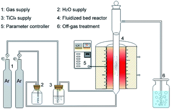
Uniform coating of TiO2 on the LiNi0.8Co0.1Mn0.1O2 (NCM811) particle surface is achieved via a FBCVD route, as shown in Fig. 1. The experimental system contains four parts, which are gas supply, reagent supply, fluidized bed reactor and off-gas treatment. Commercial NCM811 cathode material, supplied by CITIC Guoan MGL New Energy Technology Co., Ltd, China, was selected as research object, and TiCl4 (purity 99.99 wt%, supplied by Aladdin Chemistry Co., Ltd) was adopted as Ti resource. In a typical coating experiment, NCM811 powder (5.0 g) was firstly loaded into a lab-level quartz fluidized bed reactor (diameter of 17 mm). TiCl4 and H2O reagents were transported with carrier gas of Ar (purity 99.99 wt%) through two isolated rubber tubes and jetted into the fluidized bed reactor through two bubblers. The Ar gas through H2O bubbler was also used as fluidizing gas. The two reagents mutually mixed and reacted in the fluidized bed reactor, and then TiO2 was deposited on the NCM811 particle surface. After coating process, the reactor was moved away from the furnace and cooled down to room temperature. The deposition reaction parameters are listed in Table 1. The synthesized coated samples are denoted as S1–S7, and the pristine NCM811 as S0.| Carrier gas Ar (TiCl4) (ml min−1) | Fluidizing gas Ar (ml min−1) | Coating time (min) | Temperature (°C) | Samples |
|---|---|---|---|---|
| 100 | 800 | 1 | 350 | S1 |
| 100 | 800 | 3 | 350 | S2 |
| 100 | 800 | 5 | 350 | S3 |
| 100 | 800 | 10 | 350 | S4 |
| 50 | 800 | 3 | 350 | S5 |
| 200 | 800 | 3 | 350 | S6 |
| 400 | 800 | 3 | 350 | S7 |
Materials characterizations
The X-ray diffraction (XRD, X'Pert MPD Pro, Panalytical) with Cu Kα radiation (λ = 1.5408 Å) was applied to analyze the phase characteristics of samples. Field-emission scanning electron microscope (FESEM, JSM-7001F, JEOL) equipped with an energy-dispersive X-ray spectroscopy (EDS) detector (INCA X-Max) and high resolution transmission electron microscope (HRTEM, F20, Tecnai) were employed to identify the particle morphologies and microstructures. The coating contents of TiO2 were calculated from the Ti element amounts, which were measured by inductively coupled plasma optical emission spectrometry (ICP-OES, 5110, Agilent Technologies). The existing state of Ti element in the TiO2 coating layer was analyzed by X-ray photoelectron spectroscope (XPS, PHI-5000C, PerkinElmer) with Mg Kα radiation source (h = 1253.6 eV). XPSPEAK4.1 software provided by Raymond W. M. Kwok (The Chinese University of Hongkong, China) was applied to analyze the XPS data.Electrochemical measurements
The electrochemical performances of the pristine and coated samples were measured to evaluate the TiO2 coating effect. The test electrodes were fabricated by mixing active material (80 wt%), acetylene black (10 wt%) and polyvinylidene fluoride (PVDF) binder (10 wt%), using N-methyl-2-pyrrolidone (NMP) solvent. The cathode electrode was manufactured by pasting the slurry onto an aluminum foil, followed by film pressing, circular disc cutting, and vacuum drying at 120 °C for 24 h. CR2032 coin cells were assembled in an argon-filled glove box. The electrolyte is 1 M LiPF6 in a non-aqueous solution of ethylene carbonate (EC) and dimethyl carbonate (DMC) (1![[thin space (1/6-em)]](https://www.rsc.org/images/entities/char_2009.gif) :
:![[thin space (1/6-em)]](https://www.rsc.org/images/entities/char_2009.gif) 1 by volume) and the separator is porous polypropylene (Celgard 2400) film. The cells were cycled on a LAND CT2001A tester (Wuhan, China) at different current densities between 2.75 and 4.2 V. The electrochemical impedance spectra (EIS) measurements were performed using Solartron 1260 Frequency Response Analyzer combined with a Solartron 1287 potentiate with a signal amplitude of 5 mV over a frequency range of 100 kHz to 0.01 Hz.
1 by volume) and the separator is porous polypropylene (Celgard 2400) film. The cells were cycled on a LAND CT2001A tester (Wuhan, China) at different current densities between 2.75 and 4.2 V. The electrochemical impedance spectra (EIS) measurements were performed using Solartron 1260 Frequency Response Analyzer combined with a Solartron 1287 potentiate with a signal amplitude of 5 mV over a frequency range of 100 kHz to 0.01 Hz.
Results and discussion
Thermodynamics analysis for TiCl4 hydrolysis
The hydrolysis of TiCl4 is a quite complicated reaction system,28,29 which includes many transition states such as TiCl3OH, TiCl2(OH)2, TiCl(OH)3, Ti(OH)4, and etc. Ignoring these unstable intermediate states, two main hydrolysis reactions are considered in this thermodynamics analysis,30 which are described by eqn (1) and (2).| TiCl4 + H2O = TiOCl2 + 2HCl | (1) |
| TiCl4 + 2H2O = TiO2 + 4HCl | (2) |
The corresponding thermodynamics analysis results, calculated with HSC Chemistry 5.11 (Outokumpu Research Oy), are depicted in Fig. 2. Fig. 2a shows the Gibbs free energy changes (ΔG) of TiCl4 hydrolysis reactions. As observed, the ΔG of the two hydrolysis reactions gradually decrease with increasing temperatures. The TiO2-obtained hydrolysis reaction of eqn (2) shows completely negative ΔG, which are much lower than that of the TiOCl2-obtained hydrolysis reaction of eqn (1) within 0–600 °C. It means that TiCl4 hydrolysis is inclined to efficiently convert to TiO2.
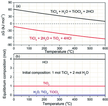 | ||
| Fig. 2 Thermodynamics analysis: (a) Gibbs free energy changes and (b) thermodynamic equilibrium composites of TiCl4 hydrolysis at various temperatures. | ||
Thermodynamic equilibrium compositions were calculated to further understand the complicated hydrolysis reactions, which is based on the total ΔG minimization method. Fig. 2b depicts the calculated thermodynamic equilibrium results. The initial conditions are set to 1 mol for TiCl4 and 2 mol for H2O, respectively. From a thermodynamic point of view, the amounts of TiO2 and HCl keep at straight lines of 1 mol and 4 mol respectively within 0–600 °C. The two changeless equilibrium values imply almost complete conversion of the given TiCl4 and H2O. This result further indicates that TiCl4 is highly reactive toward water to form the final product of TiO2.
Characterizations of the pristine NCM811
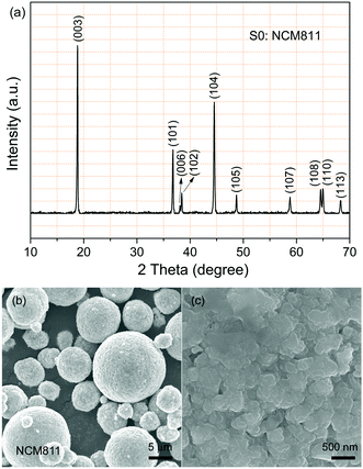
Typical commercial NCM811 was applied as kernel particle in this work. The crystal structure and particle morphology of the pristine NCM811 (sample S0) were firstly characterized by XRD and FESEM. Fig. 3a displays the XRD pattern of the pristine NCM811 particles over 2θ degree from 10° to 70°. As observed, the diffraction peaks faultlessly conforms to hexagonal α-NaFeO2 structure with R![[3 with combining macron]](https://www.rsc.org/images/entities/char_0033_0304.gif) m space group. No extra secondary phase peaks can be detected. Besides, clear splits can be observed between the (006)/(102) and (108)/(110) peaks, which indicate the existence of the layered structure.31
m space group. No extra secondary phase peaks can be detected. Besides, clear splits can be observed between the (006)/(102) and (108)/(110) peaks, which indicate the existence of the layered structure.31
The pristine NCM811 particles exhibit secondary spherical morphology with little porous, as shown in Fig. 3b and c. The particles are poly-dispersed with a log-normal size distribution, and the mean diameter is in the range of 5–12 μm. The magnified region of a single particle shown in Fig. 3c reveals that the intrinsically coarse particle is composed of numerous flake primary particles (300–500 nm) with clean surfaces.
Technological parameter effect on the controllable deposition of TiO2
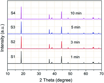
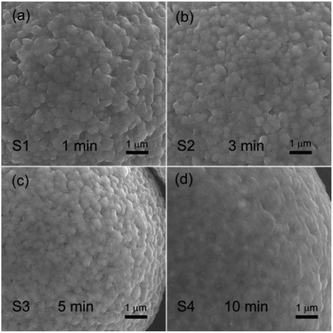
The TiO2 deposition directly influences on the properties of the coated NCM811. As a result, clarifying the technological parameter effect and realizing the controllable deposition of TiO2 are important contents in this work. Coating time and carrier gas Ar flow rate (TiCl4) are the key factors in the TiCl4 supply quantity, and thus chosen to research the technological parameter effect. The crystal features of the coated samples with increasing coating times were detected by XRD and the obtained patterns are displayed in Fig. 4. As observed, the four samples exhibit well-ordered layer hexagonal α-NaFeO2 structure, almost the same structure as the pristine NCM811. It is worth noting that no diffraction peaks of crystalline TiO2 exist, which may be attributed to the low content and the amorphous nature of TiO2. It is clear that the TiO2 coating layer deposited by FBCVD process has little influence on the NCM structure.Fig. 5 displays the magnified particle surfaces of the corresponding coated samples. As observed, after FBCVD process, the particles still remain secondary spherical morphology. At short coating times of 1 min and 3 min, see Fig. 5a and b, scarcely any changes happen to the coarse particle surface, that is to say, low coating content of TiO2 has little influence on the particle surface. With increasing the coating time to 5 min, a thin and smooth layer can be observed on the particle surface of sample S3 (Fig. 5c). The apparent core–shell structure of TiO2 coated particles is formed. Further increasing the coating time to 10 min, the TiO2 layer becomes much thicker. The secondary spherical morphology disappears and a surface smooth particle is formed, as shown in Fig. 5d.
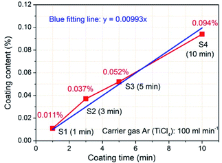
In order to determine the coating content of TiO2 in the samples after FBCVD process, ICP-OES was applied to ensure the Ti element content. Fig. 6 depicts the coating contents of TiO2 with increasing coating times, calculated based on the Ti element content measured by ICP-OES. As expected, increasing coating times significantly increases the TiO2 coating contents. When the time is 1 min, the TiO2 coating content is 0.011%. While the time increases to 10 min, the corresponding coating content reaches 0.094%. The increased TiO2 coating content results in a thickened layer, which is scrupulously corresponded to the FESEM observation result (Fig. 5d). The TiO2 coating content data were linear fitted and a blue fitting line was obtained, depicted in Fig. 6. As can be seen from the two lines, the fitting line matches well with the experimental data, that is, the TiO2 coating content has a good linear relationship with the coating time. According to the fitting line, the content of TiO2 deposition is 0.01% per minute under 100 ml min−1 of carrier gas Ar flow rate (TiCl4).
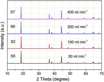
The factor of carrier gas Ar flow rate (TiCl4) is also discussed and TiO2 coated samples were prepared with increasing flow rates of carrier gas Ar (TiCl4) at a coating time of 3 min. Fig. 7 displays the corresponding XRD patterns of the coated samples. Similarly, the obtained samples exhibit the same crystal structure as the pristine NCM811. TiO2 coating with increasing flow rates of carrier gas Ar (TiCl4) has little influence on the hexagonal α-NaFeO2 layered structure, which cannot be detected in the XRD patterns.
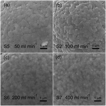
Fig. 8 shows the magnified particle surfaces of the coated samples with increasing flow rates of carrier gas Ar (TiCl4). As observed, the variation of particle surface reveals a similar tendency. When flow rates of carrier gas Ar (TiCl4) are 50 and 100 ml min−1, surface change can be hardly observed in Fig. 8a and b.
The coated particles exhibit coarse features, still remaining secondary spherical morphology. With increasing the flow rates to 200 and 400 ml min−1, a thickened and smooth layer can be clearly observed on the particle surface of sample S6 (Fig. 8c) and sample S7 (Fig. 8d). As a result, increasing flow rates of carrier gas Ar (TiCl4) can smooth the particle surface by increasing the TiO2 coating content, forming a core–shell structure of TiO2 coated particles.
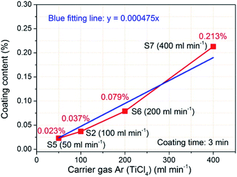
Fig. 9 shows the corresponding coating contents of TiO2 with increasing flow rates of carrier gas Ar (TiCl4). Increasing the flow rate of carrier gas Ar (TiCl4), that is, increasing the supply of gaseous TiCl4, obviously increases the TiO2 coating contents. When the flow rate is 50 ml min−1, the TiO2 coating content is 0.023%. With the carrier gas Ar flow rate increasing, the TiO2 coating content increases to 0.037% (100 ml min−1 of carrier gas Ar flow rate), 0.079% (200 ml min−1 of flow rate), and even reaches 0.213% (400 ml min−1 of flow rate). The TiO2 coating content data were also linear fitted and the calculated blue fitting line matches well with the experimental data. As a result, the TiO2 coating content has a good linear relationship with the flow rate of carrier gas Ar (TiCl4). According to the fitting line, the content of TiO2 deposition is 0.024% per 50 ml min−1 at a coating time of 3 min. The TiO2 deposition rate model, derived from the two fitting lines of the technological parameter effects, gives important information on the TiO2 deposition by FBCVD. The obtained TiO2 deposition rate, directly influenced by the coating time and the carrier gas Ar flow rate (TiCl4), is the key factor of the controllable deposition of TiO2. Accordingly, under the same main experimental parameter conditions, we can obtain coated NCM materials with designed TiO2 coating content by adjusting the coating time and the carrier gas Ar flow rate (TiCl4).
Characterizations of the coated NCM811
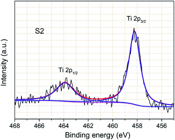
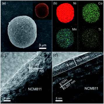
XPS measurement was carried out to clarify the existing state of Ti element in the coating layer. Fig. 10 displays the typical Ti 2p spectrum of sample S2. The observed binding energies of Ti 2p2/3 and 2p1/2 are 458.3 and 463.9 eV, respectively, which are very close to previously reported binding energy values.32,33 This confirms that the TiO2 layer remains on the sample S2 particle surface and no interaction exists between the TiO2 layer and the kernel particle. Meanwhile, The Ti 2p peak shapes are quite symmetrical, indicating that TiO2 is probably the only chemical state of Ti element.The elemental distributions of the synthesized TiO2 coated particles were examined and the results are displayed in Fig. 11a and b. One typical secondary spherical particle (sample S2) with 12 μm in diameter was selected. The elemental signals (Fig. 11b) of Ni, Co and Mn perfectly overlapped and match well with the spherical particle. The result indicates that the three elements of Ni, Co and Mn distribute homogeneously in the NCM particle. The elemental mapping of Ti element arising from TiO2 is evenly distributed on the particle surface, indicating that a uniform TiO2 layer was formed on the NCM particle surfaces. It is worth noting that the signal from Ti is much weaker. This phenomenon is due to the much lower content of Ti compared with that of the other three elements.
In order to further verify the uniform TiO2 coating layer on the particle surfaces, TEM was carried out. Fig. 11c and d presents the TEM images of the pristine NCM811 (sample S0) and TiO2 coated particle (sample S2). Distinct lattice fringes can be observed in Fig. 11c, which shows that the pristine NCM811 is well crystallized. The measured lattice interplanar spacing is 0.207 nm, well corresponding to the (104) crystal plane of layered NCM. No extra film can be detected on the smooth particle surface. In contrast, after FBCVD process, a homogenous coating layer with thickness of 6 nm can be clearly observed on the surface of the synthesized sample S2 particle. The TiO2 coating layer is amorphous, compactly attached to the surface of kernel NCM. Due to the flexible structure, the amorphous TiO2 coating layer is beneficial for lithium ion diffusion.
Mechanism of the TiO2 deposition
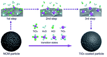
Based on the above thermodynamics analysis and the coated particle characterization results, the mechanism of TiO2 deposition on the NCM particle is concluded, as illustrated in Fig. 12. The FBCVD TiO2 deposition process, on the strength of the TiCl4 hydrolysis, can be logically divided into three representative reaction steps. In the fluidized bed reactor, the NCM particles are completely exposed in the gaseous reactive precursor atmosphere, as shown in the 1st step. H2O vapor is firstly continuously introduced into the reactor with the fluidizing gas Ar and undergoes self-limiting chemisorption to from surface hydroxyl groups. Then with the injection of gaseous TiCl4, the interaction of TiCl4 with H2O occurs, which includes many stages. Chlorine atoms in TiCl4 molecule are substituted by hydroxyl groups step by step. Some transition states such as TiCl3OH, TiCl2(OH)2, TiCl(OH)3, and Ti(OH)4 generate in the hydrolysis process, just the 2nd step. At the end of the hydrolysis, heterogeneous nucleation of TiO2 forms on the particle surface and rapid aggregative growth runs to form a uniform TiO2 film (shown in the 3rd step). Due to the high mass and heat transfer rates of FBCVD technique, the highly dispersive flowing particles are inclined to a uniform and precise deposition of TiO2.Electrochemical evaluation of TiO2 coated NCM cathode
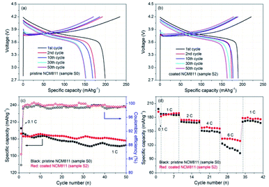
In order to investigate the TiO2 coating modification effect on electrochemical properties of NCM cathodes, the electrochemical evaluations of the synthesized TiO2 coated sample were conducted and the results are presented in Fig. 13. Fig. 13a and b display the typical charge–discharge curves of the pristine and TiO2 coated samples (sample S0 and S2, respectively) for different cycles. For the electrochemical testing, the cells were firstly activated at 0.1C for one cycle, and then sequentially cycled at 1C till 50 cycles between 2.75 and 4.2 V. The initial charge and discharge capacities of the pristine NCM811 electrode are 241.9 and 198.9 mA h g−1, respectively. The obtained initial coulombic efficiency is ca. 82.33%. By contrast, after TiO2 coating, the coated sample shows an improved initial coulombic efficiency of 85.38% with the corresponding charge and discharge capacities of 221.8 and 189.4 mA h g−1, respectively. The TiO2 coating slightly enhanced the initial coulombic efficiency from 82.33% to 85.38%. The similar voltage profiles of the two electrodes suggest that the lithiation–delithiation process and fundamental nature of the NCM electrode were not affected by the presence of TiO2 coating. It is worth noting that the voltage profiles for different cycles of the coated sample are obviously closer, implying a better reversibility than that of the pristine NCM811 electrode.Fig. 13c presents the cycling performance of the two electrodes. The specific capacities of the two electrodes tend to decrease slowly with cycling and a little scattering exists due to the environment temperature. The pristine NCM811 electrode delivers specific discharge capacities from 189.6 to 168.9 mA h g−1 for 50 cycles and the retention of capacity reaches 89.08%. After TiO2 coating, the capacity retention increases to 95.89% (from 184.7 to 177.1 mA h g−1 after 50 cycles). That is to say, the cycling stability of NCM electrode is enhanced by TiO2 coating modification. The corresponding coulombic efficiency variations of the two electrodes are shown in Fig. 13c. Notably, the coulombic efficiency of the coated sample is much better than that of the pristine NCM to some extent. A better coulombic efficiency tendency further demonstrates that constructing a TiO2 coating layer effectively enhances the cycling stability of NCM cathodes. Fig. 13d shows the rate capability of the two electrodes. The discharge capacities decrease gradually for both electrodes with increasing rates. The coated NCM811 electrode demonstrates similar capacities with the pristine NCM811 electrode at 1C, and higher capacities when the discharge rate increases. It's worth noting that the discharge capacity of the pristine NCM811 electrode drops sharply at 6C. By contrast, the coated NCM811 electrode still exhibits a relatively high and stable discharge capacity. The better rate capability for the coated NCM811 electrode at different rates proves that the TiO2 coating layer can enhance the rate performance. To sum up, the cycling stability, initial coulombic efficiency and rate capability are all intuitively improved through TiO2 coating. The FBCVD-prepared ultrathin TiO2 coating layer can effectively reduce contact area between the active NCM particles and the electrolyte, impeding the dissolution of TM ions, and protect the active NCM particles from side reactions with the electrolyte, reducing the corresponding interfacial resistance.
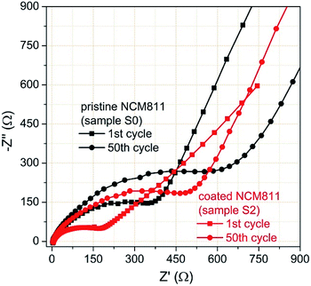
To further study the TiO2 coating effect on the electrochemical kinetics of the electrodes during cycling, EIS measurements were carried out for the two electrodes after the 1st and 50th cycles. The test coin cell is cycled in the fully charged state of 4.2 V. Fig. 14 shows the obtained Nyquist plots, which exhibit basically the same characteristics of two distinct parts including one depressed high-frequency semicircle and a long low-frequency oblique line. The high-frequency semicircle is related to the total interfacial resistance from solid electrolyte interface (SEI) film (Rf) and charge transfer (Rct), while the long low-frequency oblique line represents Warburg impedance (Zw), which is the lithium ion diffusion process within electrodes. After cycling, both electrodes show an increase of Rf and Rct. By comparing the diameters of the 1st and 50th cycles, the depressed semicircles of the coated electrode are both apparently smaller than those of the pristine NCM. The ultrathin and amorphous TiO2 coating layer is expected to reduce the interfacial resistance through preventing the side reactions between the active NCM cathode and the electrolyte.
Conclusions
In this work, we demonstrate a novel FBCVD approach to enable scalable and high yield synthesis of TiO2 coated nickel-rich NCM cathode based on the TiCl4 hydrolysis principle. Great concerns were focused on the effects of coating time and TiCl4 supply rate on the TiO2 deposition behaviors. Based on the obtained technological parameter effects, a utility rate model of TiO2 deposition was induced, promoting the controllable deposition of TiO2. The FBCVD TiO2 deposition mechanism was fundamentally analyzed. After FBCVD process, an amorphous and uniform TiO2 layer was compactly attached on the particle surface. Electrochemical evaluations verified the excellent effect of the TiO2 coating on the enhancement of the capacity retention. In view of its controllable and cost-effective nature, the FBCVD metal oxides coating process could also be applied to other transition metal oxide coating, which will greatly promote the development of nickel-rich NCM cathodes.Conflicts of interest
There are no conflicts to declare.Acknowledgements
This work was financially supported by National Natural Science Foundation of China (51602313 and 11805227), Beijing Natural Science Foundation of China-Haidian Special Project (L182065), Key Research and Development Project of Shandong Province (2017CXGC0502) and International Science and Technology Cooperation Project of Shandong Academy of Sciences (2019GHPY17).Notes and references
- Q. Li, R. Dang, M. Chen, Y. Lee, Z. Hu and X. Xiao, ACS Appl. Mater. Interfaces, 2018, 10, 17850–17860 CrossRef CAS PubMed.
- H. Lu, H. Zhou, A. M. Svensson, A. Fossdal, E. Sheridan, S. Lu and F. Vullum-Bruer, Solid State Ionics, 2013, 249–250, 105–111 CAS.
- C. Hua, K. Du, C. Tan, Z. Peng, Y. Cao and G. Hu, J. Alloys Compd., 2014, 614, 264–270 CrossRef CAS.
- Y. Xu, W. Xiang, Z. Wu, C. Xu, Y. Li, X. Guo, G. Lv, X. Peng and B. Zhong, Electrochim. Acta, 2018, 268, 358–365 CrossRef CAS.
- H. Kim, M. G. Kim, H. Y. Jeong, H. Nam and J. Cho, Nano Lett., 2015, 15, 2111–2119 CrossRef CAS PubMed.
- S. Chen, T. He, Y. Su, Y. Lu, L. Bao, L. Chen, Q. Zhang, J. Wang, R. Chen and F. Wu, ACS Appl. Mater. Interfaces, 2017, 9, 29732–29743 CrossRef CAS PubMed.
- X. Xiong, Z. Wang, H. Guo, Q. Zhang and X. Li, J. Mater. Chem. A, 2013, 1, 1284–1288 RSC.
- Y. K. Sun, M. J. Lee, C. S. Yoon, J. Hassoun, K. Amine and B. Scrosati, Adv. Mater., 2012, 24, 1192–1196 CrossRef CAS PubMed.
- K. Yang, L. Fan, J. Guo and X. Qu, Electrochim. Acta, 2012, 63, 363–368 CrossRef CAS.
- J. Shi, C. W. Yi and K. Kim, J. Power Sources, 2010, 195, 6860–6866 CrossRef CAS.
- W. Cho, S. M. Kim, K. W. Lee, J. H. Song, Y. N. Jo, T. Yim, H. Kim, J. S. Kim and Y. J. Kim, Electrochim. Acta, 2016, 198, 77–83 CrossRef CAS.
- Y. Chen, Y. Zhang, B. Chen, Z. Wang and C. Lu, J. Power Sources, 2014, 256, 20–27 CrossRef CAS.
- X. Xiong, D. Ding, Z. Wang, B. Huang, H. Guo and X. Li, J. Solid State Electrochem., 2014, 18, 2619–2624 CrossRef CAS.
- J. Zheng, J. Li, Z. Zhang, X. Guo and Y. Yang, Solid State Ionics, 2008, 179, 1794–1799 CrossRef CAS.
- Y. S. Jung, A. S. Cavanagh, L. A. Riley, S. H. Kang, A. C. Dillon, M. D. Groner, S. M. George and S. H. Lee, Adv. Mater., 2010, 22, 2172–2176 CrossRef CAS PubMed.
- H. M. Cho, M. V. Chen, A. C. MacRae and Y. S. Meng, ACS Appl. Mater. Interfaces, 2015, 7, 16231–16239 CrossRef CAS PubMed.
- X. Zhang, I. Belharouak, L. Li, Y. Lei, J. W. Elam, A. Nie, X. Chen, R. S. Yassar and R. L. Axelbaum, Adv. Energy Mater., 2013, 3, 1299–1307 CrossRef CAS.
- C. Qin, J. Cao, J. Chen, G. Dai, T. Wu, Y. Chen, Y. Tang, A. Li and Y. Chen, Dalton Trans., 2016, 45, 9669–9675 RSC.
- P. Poodt, R. Knaapen, A. Illiberi, F. Roozeboom and A. V. Asten, J. Vac. Sci. Technol., A, 2012, 30, 01A142 CrossRef.
- C. H. See and A. T. Harris, Ind. Eng. Chem. Res., 2007, 46, 997–1012 CrossRef CAS.
- M. Liu, R. Liu, B. Liu and Y. Shao, Procedia Eng., 2015, 102, 1890–1895 CrossRef CAS.
- M. Liu, Y. Shao and B. Liu, Nucl. Eng. Des., 2012, 250, 277–283 CrossRef CAS.
- R. Liu, M. Liu, J. Chang, Y. Shao and B. Liu, J. Nucl. Mater., 2015, 467, 917–926 CrossRef CAS.
- Z. Zhang, Z. Gong and Y. Yang, J. Phys. Chem. B, 2004, 108, 17546–17552 CrossRef CAS.
- H. Yang, L. Liu, F. Yang and J. C. Yu, J. Zhejiang Univ., Sci., A, 2008, 9, 981–987 CrossRef CAS.
- M. Rigo, P. Canu, L. Angelin and G. D. Valle, Ind. Eng. Chem. Res., 1998, 37, 1189–1195 CrossRef CAS.
- L. Ma, R. Nuwayhid, T. Wu, Y. Lei, K. Amine and J. Lu, Adv. Mater. Interfaces, 2016, 3, 1600564 CrossRef.
- R. H. West, G. J. O. Beran, W. H. Green and M. Kraft, J. Phys. Chem. A, 2007, 111, 3560–3565 CrossRef CAS PubMed.
- V. O. Kotsyubynsky, I. F. Myronyuk, L. I. Myronyuk, V. L. Chelyadyn, M. H. Mizilevska, A. B. Hrubiak, O. K. Tadeush and F. M. Nizamutdinov, Materialwiss. Werkstofftech., 2016, 47, 2–3 CrossRef.
- T. Wang, A. M. Navarrete-Lopez, S. Li and D. A. Dixon, J. Phys. Chem. A, 2010, 114, 7561–7570 CrossRef CAS PubMed.
- J. Kong, H. Zhai, C. Ren, G. Tai, X. Yang, F. Zhou, H. Li, J. Li and Z. Tang, J. Solid State Electrochem., 2014, 18, 181–188 CrossRef CAS.
- S. A. Simakov and Y. Tsur, J. Nanopart. Res., 2007, 9, 403–417 CrossRef CAS.
- Y. Masuda, Y. Jinbo and K. Koumoto, Sci. Adv. Mater., 2009, 1, 138–143 CrossRef CAS.
| This journal is © The Royal Society of Chemistry 2019 |

