 Open Access Article
Nano-architecture of silica nanoparticles as a tool to tune both electrochemical and catalytic behavior of NiII@SiO2
Mikhail N. Khrizanforov *,
Svetlana V. Fedorenko,
Asia R. Mustafina
 ,
Vera V. Khrizanforova
 ,
Kirill V. Kholin,
Irek R. Nizameev,
Tatyana V. Gryaznova
 ,
Valeriya V. Grinenko
 and
Yulia H. Budnikova
Arbuzov Institute of Organic and Physical Chemistry, FRC Kazan Scientific Center, Russian Academy of Sciences, 420088, Arbuzov str. 8, Kazan, Russian Federation. E-mail: khrizanforov@iopc.ru
First published on 23rd July 2019
Abstract
The present work introduces a facile synthetic route for efficient doping of [NiII(bpy)x] into silica nanoparticles with various sizes and architectures. Variation of the latter results in different concentrations of the NiII complexes at the interface of the composite nanoparticles. The UV-Vis analysis of the nanoparticles reveals changes in the inner-sphere environment of the NiII complexes when embedded into the nanoparticles, while the inner-sphere of NiII is invariant for the nanoparticles with different architecture. Comparative analysis of the electrochemically generated redox transformations of the NiII complexes embedded in the nanoparticles of various architectures reveals the latter as the main factor controlling the accessibility of NiII complexes to the redox transitions which, in turn, controls the electrochemical behavior of the nanoparticles. The work also highlights an impact of the nanoparticulate architecture in catalytic activity of the NiII complexes within the different nanoparticles in oxidative C–H fluoroalkylation of caffeine. Both low leakage and high concentration of the NiII complexes at the interface of the composite nanoparticles enables fluoroalkylated caffeine to be obtained in high yields under recycling of the nanocatalyst five times at least.
Introduction
The design and development of an “ideal” catalyst is the main prerequisite for carrying out organic chemistry reactions in the framework of “green chemistry”. The nanoparticulate approach to the design and synthesis of heterogeneous catalysts has gained growing attention in recent decades since it provides a tool for a combination of the catalytic efficiency of homogeneous catalysts with the facile separation from synthetic mixtures of heterogeneous ones.1–11 In particular, conversion of molecular complexes of transition metals widely applied in homogeneous catalysis of organic reactions into nanoparticulate catalysts can significantly facilitate their recycling. It is worth noting that the catalytic activity of nanoparticulate catalysts is greatly dependent on the surface activity of nanoparticles which, in turn, is affected by their size and nanoarchitecture. However, work highlighting the size and nano-architecture requirements for efficient catalytic behavior is mostly exemplified by noble metals in zero valences.12–20The high catalytic activity of Ni complexes exemplified by the great number of organic and electrochemical reactions21–34 makes them promising alternate to noble metal-based nanoparticles, although the homogeneous catalysis by NiIII/II/I/0 complexes suffers from the lack of recyclability. The embedding of metal complexes into silica or other matrix is a well-known facile and efficient approach of converting molecular metal complexes to their nanoparticular forms.35–38 Moreover, the catalytic efficiency of such composite silica nanoparticles has been already exemplified.35–38 However, the nanoparticulate features controlling catalytic efficiency of the composite nanoparticles are still insufficiently recognized.
Alkaline-catalyzed hydrolysis of TEOS is most convenient synthetic route for gaining in spherical shape and universe size of silica nanoparticles (SNs).39–41 The simple addition of any dopants to the synthetic mixture results in their embedding into the silica confinement in the form of ultra-small nano-aggregates.35,42 This forms the plum-pudding architecture of the nanoparticles which, in turn, can be modified by predominant localization of dopants in core or interfacial zones of nanoparticles.43 Architecture of SNs doped by different functional molecules is of great impact on the functionality of the nanoparticles exemplified by sensing and imaging abilities.43–45
Catalytic behavior of such nanoparticles require enough accessibility of the doped complexes to electrochemically induced reduction or oxidation which, in turn, is a reason for specific requirements to both a size and architecture of the nanoparticles. It is worth noting that our previous report reveals doping of NiII complexes into silica nanoparticles with further electrochemical generation of the NiIII complexes as facile approach for synthesis of stable in time composite nanoparticles (90–100 nm) with rather high and recyclable catalytic activity in oxidative C–H alkylation.35 Nevertheless, the reported results remain unclear the issue on the effect of size and architecture of the composite nanoparticles on their catalytic behavior.
The present work is aimed at highlighting the features that control catalytic behavior of the Ni(II)-doped composite SNs in the oxidative C–H fluoroalkylation of caffeine. Thus, an impact of the size and nano-architecture of the composite nanoparticles on their catalytic behavior is discussed herein. The nanoparticulate architecture is changed by variation of concentration and/or distribution of the NiII complexes within the silica spheres for differentiating interfacial accessibility of the NiII complexes to oxidation and interactions with substrates. For this reason, the redox potential values of the NiII complexes encapsulated into the nanoparticles of the various architecture are discussed in correlation with their catalytic behavior. The synthetic approaches for controlling both size and nano-architecture of the composite nanoparticles are also introduced.
Results and discussion
Stöber procedure opens great opportunities for modification of the silica spheres size by variation of the synthetic conditions.39–41 The time conditions variation from 30 to 60 and 120 minutes at the TEOS![[thin space (1/6-em)]](https://www.rsc.org/images/entities/char_2009.gif) :
:![[thin space (1/6-em)]](https://www.rsc.org/images/entities/char_2009.gif) Ni (521
Ni (521![[thin space (1/6-em)]](https://www.rsc.org/images/entities/char_2009.gif) :
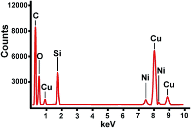
:![[thin space (1/6-em)]](https://www.rsc.org/images/entities/char_2009.gif) 1) ratio enables to differentiate the size of the SNs from 31–46 nm (SNs-1) to 50–79 nm (SNs-2) and 60–90 nm (SNs-3). The TEM images presented in Fig. 1 illustrate the difference between the synthesized SNs. The content of Ni in the composite nanoparticles was quantitatively evaluated by ICP-OES technique, while the use of EDS method (Fig. 2) provides additional confirmation of the presence of Ni in the composite nanoparticles. The Si
1) ratio enables to differentiate the size of the SNs from 31–46 nm (SNs-1) to 50–79 nm (SNs-2) and 60–90 nm (SNs-3). The TEM images presented in Fig. 1 illustrate the difference between the synthesized SNs. The content of Ni in the composite nanoparticles was quantitatively evaluated by ICP-OES technique, while the use of EDS method (Fig. 2) provides additional confirmation of the presence of Ni in the composite nanoparticles. The Si![[thin space (1/6-em)]](https://www.rsc.org/images/entities/char_2009.gif) :
:![[thin space (1/6-em)]](https://www.rsc.org/images/entities/char_2009.gif) Ni molar ratios calculated from the ICP-OES data (Table 1) also indicate the difference between the synthesized nanoparticles. It is worth noting that the content of NiII tends to decrease with the growth of the SNs, which, in turn, reveals the inhomogeneous distribution of the NiII complexes within silica spheres. In particular, concentration of the complexes in the interfacial zone of the SNs tends to decrease on going from SNs-1 to SNs-2 and SNs-3.
Ni molar ratios calculated from the ICP-OES data (Table 1) also indicate the difference between the synthesized nanoparticles. It is worth noting that the content of NiII tends to decrease with the growth of the SNs, which, in turn, reveals the inhomogeneous distribution of the NiII complexes within silica spheres. In particular, concentration of the complexes in the interfacial zone of the SNs tends to decrease on going from SNs-1 to SNs-2 and SNs-3.
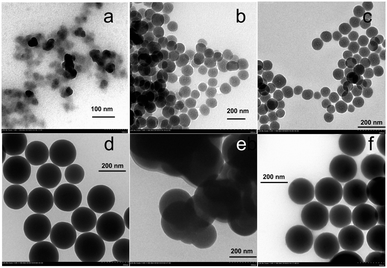 | ||
| Fig. 1 TEM images of silica nanoparticles SNs 1–6, doped Ni(BF4)2bpy3, where a – SNs-1, b – SNs-2, c – SNs-3, d – SNs-4, e – SNs-5, f – SNs-6. | ||
![[thin space (1/6-em)]](https://www.rsc.org/images/entities/char_2009.gif) :
:![[thin space (1/6-em)]](https://www.rsc.org/images/entities/char_2009.gif) Ni of the obtained nanoparticles SNs-1–SNs-6
Ni of the obtained nanoparticles SNs-1–SNs-6
| Sample | D (TEM) | Molar ratio of Si![[thin space (1/6-em)]](https://www.rsc.org/images/entities/char_2009.gif) : :![[thin space (1/6-em)]](https://www.rsc.org/images/entities/char_2009.gif) Ni, ±10% Ni, ±10% |
|
|---|---|---|---|
| Si | Ni | ||
| SNs-1 | 31–46 nm | 1 | 0.02 ± 0.002 |
| SNs-2 | 50–79 nm | 1 | 0.012 ± 0.0012 |
| SNs-3 | 60–90 nm | 1 | 0.0053 ± 0.0005 |
| SNs-4 | 189 nm | 1 | 0.00126 ± 0.0001 |
| SNs-5 | ∼200 nm | 1 | 0.00235 ± 0.0002 |
| SNs-6 | 204–241 nm | 1 | 0.00138 ± 0.0001 |
The further modification of the Stöber procedure39 was done by the increased TEOS![[thin space (1/6-em)]](https://www.rsc.org/images/entities/char_2009.gif) :
:![[thin space (1/6-em)]](https://www.rsc.org/images/entities/char_2009.gif) Ni (782
Ni (782![[thin space (1/6-em)]](https://www.rsc.org/images/entities/char_2009.gif) :
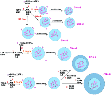
:![[thin space (1/6-em)]](https://www.rsc.org/images/entities/char_2009.gif) 1) ratio under the growth of the silica spheres for six hours for the greater size of the SNs. Indeed, the synthesized SNs-4 are 189 nm sized with the smaller Ni content. The SNs-5 and SNs-6 were synthesized through the two-step addition of TEOS in order to minimize the concentration of the NiII complexes in the interfacial zone of the nanoparticles. For this reason, the SNs-4 grown within six hours were washed from the unreacted NiII complexes, TEOS and ammonia with further addition of TEOS and ammonia without NiII complex. Indeed, the modified procedure enabled to get SNs-5 and SNs-6 which differentiates from each other by thicker additional silica adlayer for SNs-6 versus SNs-5. The thickness of the additional silica adlayer was, in turn, varied by the amount of the TEOS added at the second step. The variations of the synthetic procedure resulting in different architectures of the nanoparticles are illustrated by the Scheme 1, while their TEM images in the Fig. 1 were used for the size values specification.
1) ratio under the growth of the silica spheres for six hours for the greater size of the SNs. Indeed, the synthesized SNs-4 are 189 nm sized with the smaller Ni content. The SNs-5 and SNs-6 were synthesized through the two-step addition of TEOS in order to minimize the concentration of the NiII complexes in the interfacial zone of the nanoparticles. For this reason, the SNs-4 grown within six hours were washed from the unreacted NiII complexes, TEOS and ammonia with further addition of TEOS and ammonia without NiII complex. Indeed, the modified procedure enabled to get SNs-5 and SNs-6 which differentiates from each other by thicker additional silica adlayer for SNs-6 versus SNs-5. The thickness of the additional silica adlayer was, in turn, varied by the amount of the TEOS added at the second step. The variations of the synthetic procedure resulting in different architectures of the nanoparticles are illustrated by the Scheme 1, while their TEM images in the Fig. 1 were used for the size values specification.
It is also worth noting that the thickening of the external silica adlayer on going from the SNs-4 to the SNs-5(6) results in the further decrease of the Ni-content (Table 1). Moreover, the two-step procedure is the obvious prerequisite for the smaller interfacial concentration of the NiII complexes in the SNs-5 and SNs-6 versus SNs-4.
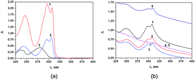
It is worth noting the tendency revealed in our previous report that the doping of the initial [NiII(bpy)3] complexes into the SNs is accompanied by their partial degradation to [NiII(bpy)x] (x < 2). The degradation is easily revealed by the changed spectral pattern of the complexes within the SNs versus the [NiII(bpy)3], while its comparison with that of [NiII(bpy)] in the solutions (Fig. 3) confirms the partial degradation resulted from the doping procedure. Nevertheless, the spectral patterns revealed for the SNs-1(2–6) are rather similar, which indicates that half of an hour is enough for the partial degradation of the initial complex.
The spectral data in Fig. 3 represent the low-intensity bands in the electronic spectra of the supernatant solutions after the continuous stirring of the nanoparticles in the acetonitrile solutions which provide the indication of very low leaching of the complex from the SNs to the supernatant solutions (Fig. 4).
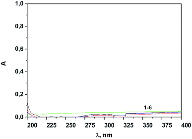 | ||
| Fig. 4 The absorption spectra of the supernatants after 1 hour of continuous stirring followed by the separation of SNs-1–6 (1–6) (0.2 g L−1) in CH3CN. | ||
Concluding the subsection, it is worth noting that a half of an hour is enough for the embedding of the major part of the NiII complex into silica spheres, although their size is rather small and the uniformity in the size is also small (30–46 nm). The longer time is required for the synthesis of the greater sized silica spheres, while the Ni![[thin space (1/6-em)]](https://www.rsc.org/images/entities/char_2009.gif) :
:![[thin space (1/6-em)]](https://www.rsc.org/images/entities/char_2009.gif) Si ratio tends to decrease with the size growth. The results point to predominant localization of the NiII complexes in the core zones of the silica spheres, while the concentration of the complexes in the interfacial zone tends to decrease with the size growth. It is also worth noting that regardless of the time conditions NiII complexes embedded into the silica spheres tend to lose one or two bpy ligands due to the ligand substitution processes. The latter are very difficult to specify, since both ammonia and hydroxyl anions existing in the synthetic mixture and Si–O− groups at the silica surface can be bound with [NiII(bpy)x] in the inner- or outer-sphere modes.
Si ratio tends to decrease with the size growth. The results point to predominant localization of the NiII complexes in the core zones of the silica spheres, while the concentration of the complexes in the interfacial zone tends to decrease with the size growth. It is also worth noting that regardless of the time conditions NiII complexes embedded into the silica spheres tend to lose one or two bpy ligands due to the ligand substitution processes. The latter are very difficult to specify, since both ammonia and hydroxyl anions existing in the synthetic mixture and Si–O− groups at the silica surface can be bound with [NiII(bpy)x] in the inner- or outer-sphere modes.
Electrochemical study
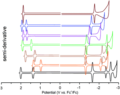
Accurate comparative analysis of nickel(II) complexes redox behavior under their encapsulation into variously sized silica nanoparticles is rather complicated task because of difference in their diffusion rates. However, cyclic voltammetry (CV) using a phosphonium salt based paste electrode is very promising alternate to cyclic voltammetry in solutions which was previously proven for analyzing insoluble and poorly soluble complexes. Thus, the use of such electrochemical technique enabled to get the CV curves for both SNs-1(2–6) and initial [Ni(bpy)3](BF4)2 complex in the same conditions (Fig. 5 and Table 2). We used semi-derivative voltammetry to confirm the redox properties for all SNs-1(2–6) and initial [Ni(bpy)3](BF4)2 complex (Fig. 7). The semi-derivative voltammetry shows the reversibility of redox transitions Ni(II) ↔ Ni(0), Ni(II) ↔ Ni(III), Ni(III) ↔ Ni(IV), Ni(II) ↔ Ni(IV).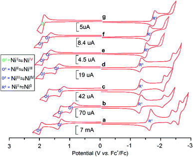 | ||
| Fig. 5 CVs for (a) [NiII(bpy)3] (b) SNs-1; (c) SNs-2; (d) SNs-3; (e) SNs-4, (f) SNs-5, (g) SNs-6 WE: CPE, CH3CN, 10−1 M Bu4NBF4 potentials vs. Ag/AgCl recalculated to Fc+/Fc. | ||
| Reduction | Oxidation | |||
|---|---|---|---|---|
| 1Ecp/Eap, V | 2Ecp/Eap, V | 1Eap/Ecp, V | 2Eap/Ecp, V | |
| SNs-1 | −1.40/−1.28 | −2.15/−2.03 | 1.03/0.95 | 1.50/1.40 |
| SNs-2 | −1.41/−1.32 | −2.21/−2.15 | 1.49/1.40 | 1.83/1.76 |
| SNs-3 | −1.45/−1.39 | −2.56/−2.50 | 1.51/1.44 | 1.90/1.83 |
| SNs-4 | −1.55/−1.49 | — | 1.81/1.60 | 1.87/1.83 |
| SNs-5 | −1.61/−1.55 | — | 1.84/1.62 | 1.87/1.84 |
| SNs-6 | −1.92/−1.85 | — | 1.85/1.79 | — |
| [NiII(bpy)3] | −1.65/−1.59 | −2.34/−2.27 | 1.34/1.26 | 2.01/1.95 |
The electrochemical reduction and oxidation of the NiII complexes in both molecular and nanoparticulate forms occurs up to Ni0 and NiIII correspondingly with one exception for SNs-6, where the electrochemical behavior is manifested by one two-electron oxidation step NiII/NiIV. The significant difference in the potential values of SNs-1 and [Ni(bpy)3](BF4)2 correlates with the differences in the inner-sphere of NiII arisen from the substitution of one or two bpy ligands by Si–O− donor groups.
The potential values of SNs-1(2–6) reveal significant dependence on their size, although the spectral properties of the nanoparticles (Fig. 3) indicate the similarity in the inner-sphere environment of NiII ions within SNs-1(2–6). However, a redox behavior of transition metal complexes is greatly affected by polarity or specific interactions arisen from their outer-sphere environment.46–50 It is worth assuming that the difference in size and nanoparticulate architecture of SNs-1(2–6) leads to the different distribution of the doped complexes between the interfacial and core zones of the SNs. It is also worth noting that the complexes located in the interfacial zone are more accessible to any external stimulus than the complexes within the core zone of nanoparticles.43,44,51 Moreover, the extent of the interfacial complexes tends to increase with the decrease in size of the nanoparticles.52
The similar tendency should be valid for [NiII(bpy)x] complexes inside the growing in size (Table 1) SNs-1(2–6). The tendency is enhanced by the specific synthetic conditions applied in obtaining of SNs-1(2–6). In particular, the increase in size of SNs-1(2–6) results from both longer time for their growth and the greater TEOS concentrations, while the concentration of initial NiII complex added at the beginning of the synthesis remains invariant. This results in the dramatic decrease in the concentration of the interfacial NiII complexes on going from SNs-1 to SNs-6. The results point to correlation of the electrochemical potential values of NiII complexes inside SNs-1(2–6) with their nanoarchitecture.
Taking into account electrochemical reversibility of the redox transformations of the NiII complexes inside SNs-1(2–6) (Fig. 5) the corresponding redox potential values (Table 2) provide a direct measure of thermodynamic feasibility of the electrochemical behavior of the NiII complexes inside the nanoparticles. This, in turn, is the prerequisite for evaluating a difference between the energies of the boundary molecular orbitals for the nanoparticulate forms of NiII complexes from the electrochemical gap ΔE. The latter is the difference between standard redox potentials, or E1/2 of oxidation and reduction which is designated by eqn (1).
| ΔE = EOx1/2 − ERed1/2 | (1) |
The importance of ΔE values was illustrated by the previous reports on organic compounds highlighting a correlation between the energy required to add one electron to a molecule, the standard reduction potential, and the energy of the LUMO.51
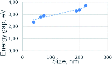
The energy of the LUMO can be approximated by the electron affinity, which is the energy required to add an electron to an atom or molecule in the gas phase. In a similar fashion, correlations have been found for organic molecules between the standard oxidation potentials and the ionization potentials.31,52–56 Fig. 6 illustrates the correlation of the ΔE values with the size of the nanoparticles, since the growth in size, in turn, correlates with localization of the NiII complexes within the silica spheres. In our case, the smallest particles are characterized by the smallest value of ΔE, and it is much smaller than ΔE of the precursor, which is Ni(BF4)2bpy3 complex (Fig. 5). Further, with an increase in the particle size, the ΔE gap expands due to the growth of both anodic and cathodic potentials simultaneously. In this case, the difference between the potentials of the consecutive oxidation NiII/NiIII/NiIV decreases. As a result, for the SNs of the largest size (SNs-6), only one stage of anodic oxidation is observed with synchronous transfer of two electrons, NiII/NiIV.
Ni-catalyzed oxidative C–H fluoroalkylation of caffeine
Joint electrolysis of caffeine and perfluoroheptanoic acid in the presence of SNs-1(2–6) (Ni, 1 mol%) in CH3CN at the potential of NiII first oxidation peak yields to perfluoroalkylation product. CO2 gas evolution during the electrolysis was observed at room temperature. The isolated yields vary within 27–93% subject to the nanoparticulate architecture (Table 3 and Fig. 8). Moreover, the low leakage of the NiII complexes from SNs-1(2–6) enabled the nanoparticles to be recycled and reused 5 times for C(sp2)–H bond functionalization (Table 3). The fluoroalkylated caffeine yield have been decreased by 6–8% after fifth synthesis with the same nanocatalyst sample.| Product yields NMR yield (isolated yield), [%] | |||||
|---|---|---|---|---|---|
| 1st | 2nd | 3rd | 4th | 5th | |
| NP type 1 | 70(63) | 69(60) | 66(56) | 64(53) | 62(50) |
| NP type 2 | 91(75) | 91(75) | 89(73) | 88(73) | 87(70) |
| NP type 3 | 93(76) | 93(76) | 92(75) | 92(75) | 91(73) |
| NP type 4 | 45(35) | 44(34) | 44(32) | 42(32) | 42(32) |
| NP type 5 | 47(38) | 46(37) | 46(37) | 45(34) | 45(34) |
| NP type 6 | 27(20) | 27(20) | 27(20) | 27(20) | 27(20) |
| Blank silica | 0(0) | ||||
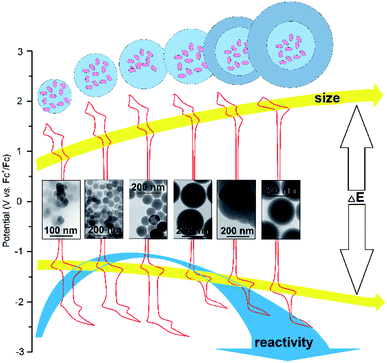 | ||
| Fig. 8 Nano-architecture of silica nanoparticles doped with NiII complexes as a tool to tune both electrochemical and catalytic behavior of NiII. | ||
The yield values (Table 3) are greater under the use of SNs-1(2, 3) than those evaluated for SNs-4(5, 6). This is in good agreement with the difference in their nanoparticulate architecture which, in turn, is the reason for significant decrease of the NiII complexes accessibility to interaction with the substrates. The correlation between the nanoparticulate features of SNs-1(2–6) and their electrochemical and catalytic behavior is illustrated by Fig. 8. The tendency (Table 3 and Fig. 8) highlights the smaller sized SNs-1(2, 3) versus the greater sized SNs-4(5, 6) as more prominent candidates for both facile redox and greater catalytic activities of the nanoparticles. It is also worth noting that both yield and potential values of SNs-1(2–6) are affected by the nanoparticulate architecture in the similar way, while the increase of the yield values on going from SNs-1 to SNs-3 disagrees with the tendency.
The disagreement can be explained by the factors beside the size and nano-architecture affecting the catalytic activity of SNs-1(2–6) in the acetonitrile solutions.
It is worth assuming the greater aggregation of SNs-1 versus SNs-2(3) as the factor decreasing their catalytic activity, since the greater aggregation of the smaller sized SNs in comparison with the greater sized ones is well documented.52
Conclusions
The present work introduces the well-known Stöber procedure as facile basis for further modification aimed at the embedding of NiII complexes into silica nanoparticles. The easy variation of the synthetic conditions enables to vary the nanoparticulate architecture from “core” to “core–shell” with different silica shell thickness. The analysis of the electrochemical behavior of the nanoparticles with different nano-architecture reveals great impact of the latter on the facility of redox transformations for the NiII complexes within silica nanoparticles. In particular, the thickness of silica shell is revealed as the factor controlling the interfacial location of the complexes which, in turn, is the main reason for their redox behavior. Moreover, the results highlight the variation of the nanoparticulate architecture as a powerful tool to modify the catalytic activity of NiII complexes in oxidative C–H fluoroalkylation of caffeine. Thus, the revealed regularities provide convenient synthetic tool for controlling the functionality of the nanoparticles by variation of their architecture, which for the best of our knowledge is rather rare documented in literature.Experimental
Materials
Tetraethyl orthosilicate (TEOS, 98%) and ammonium hydroxide (28–30%) were purchased from Acros. C6F13COOH was purchased from P&M Invest and used without further purification. CH3CN (CHROMASOLV® Plus, ≥99.9%, by Acros Organics) was used without any preliminary purification. 2.2′-bipyridine (99%, from Acros Organic), and C6H6 (CHROMASOLV® Plus, ≥99.9%, by Sigma Aldrich) were used without any preliminary purification as well.The ethanol and TEOS were purified by distillation.
Et4NBF4 was obtained by mixing an aqueous solution of Et4NOH (30–35%) with HBF4 for to a neutral indicator reaction. Et4NBF4 precipitated from the reaction mixture as white crystals, which were separated by filtering. The powder salt was further recrystallized from diethyl ether and dried for 2 to 3 days in a vacuum at 55 °C for dehydration.
The leaching of [(bpy)xNiII] complexes from the silica nanoparticles SNs-1-6 was monitored using the following procedure: a dispersion of silica nanoparticles SNs-1-6 in CH3CN (C = 0.2 g L−1) was stirred for 1 hour at 750 rpm. Afterwards, Ni(II) doped silica nanoparticles SNs-1-6 were precipitated by centrifugation at 12![[thin space (1/6-em)]](https://www.rsc.org/images/entities/char_2009.gif) 000 rpm. The supernatants' absorption spectra after phase separation are shown in Fig. 4.
000 rpm. The supernatants' absorption spectra after phase separation are shown in Fig. 4.
Methods
TEM-EDX experiments
Experiments were carried out on Hitachi HT7700 transmission electron microscope with energy-dispersive X-ray detector from Thermo Scientific. The accelerating voltage was equal 80 kV. The accumulation time of one spectrum was 300 s.UV-Vis spectra were recorded on a Lambda 35 spectrophotometer (PerkinElmer).
Ni and Si were identified in the SNs-1-6 colloids using simultaneous inductively coupled plasma atomic emission spectrometry (ICP-AES) model iCAP 6300 DUO by Varian Thermo Scientific Company equipped with a CID detector. This spectrometer enables the simultaneous measurement of peak heights within the 166 to 867 nm range. The optical resolution is less than 0.007 nm to 200 nm. As for the working frequency, it is 27.12 MHz. Together, the radial and axial view configurations enable optimal peak height measurements with suppressed spectral noises.
Electrosynthesis
Preparative electrolysises were performed using a B5-49 direct current source in a thermostatically controlled, cylindrical, sectioned 100 mL electrolyser (a three-electrode cell). Platinum with a surface area of 20 cm2 was used for the cathodes and a platinum rod was used as the anode. The working electrode potential was determined using reference electrode Ag/AgCl. During electrolysis, the electrolyte was stirred using a magnetic stirrer, the saturated Et4NBF4 solution in DMF was used as an analyte, and the anode compartment was separated by ceramic membrane. The mass spectra were then recorded in EI mode using ThermoQuest TRACE MS.NMR measurements
A NMR measurements were performed in the NMR department (A.E. Arbuzov Institute Organic and Physical Chemistry) of the Federal Collective Spectral Analysis Center for physical and chemical studies on the structure, properties, and composition of matter and materials. NMR experiments were conducted using Bruker spectrometers AVANCE-400 (400.1 MHz (1H), 376.5 MHz (19F), 100.6 MHz (13C)) and AVANCE-600 (600.1 MHz (1H), 150.9 MHz (13C)) equipped with a pulsed gradient unit capable of producing magnetic field pulse gradients in the z-direction of 53.5 G cm−1. All spectra were acquired in a 5 mm gradient inverse broad band probe head. As a result, chemical shifts were reported on the δ (ppm) scale relative to the residual 1H and 13C C6D6 signal resulting in external C6F6 (−164.9 ppm) for 19F NMR spectra.Electrochemistry
Electrochemical measurements were taken on a BASiEpsilonE2P electrochemical analyzer (USA). The program concerned Epsilon-EC-USB-V200 waves. A conventional three-electrode system was used with glassy carbon for carbon paste electrode (CPE) solutions for powder samples as the working electrode, the Ag/AgCl (0.01 M) electrode as the reference electrode, and a Pt wire as the counter electrode. 0.1 M Et4NBF4 was used as the supporting electrolyte to determine the current–voltage characteristics.To study the powder samples, a modified CPE working electrode was used,2,3 which was prepared as follows: the carbon particles/phosphonium salt (dodecyl(tri-tert-butyl)phosphonium tetrafluoroborate) composite electrode was prepared using a grinding a mixture of graphite powder and phosphonium salt with a 90/10 (w/w) ratio in mortar giving it a homogeneous mass.56 A modified electrode was also devised in a similar manner except that a portion (ca. 5%) of the graphite powder was replaced by the Ni complex (or Ni@SO2) powder under study. As a result, a portion of the resulting paste was packed firmly into the (3 mm in diameter) a Teflon holder cavity.
Scanning electron microscopy analysis
In this case, an immobilized catalyst was studied using electron microscopy analysis before and after a perfluoroalkylation reaction. The solutions were applied to the titanium foil surface previously cleared using sonification in acetone. Then, the sample was exsiccated at low heat (no higher than 40 °C). The morphology of the sample surfaces was characterized by an SEM plan-view using a high-resolution microscope that Merlin Carl Zeiss combined with ASB (Angle Selective Backscattering) and SE InLens (Secondary Electrons Energy selective Backscattering) detectors, which was also equipped for an energy-dispersive X-ray spectroscopy (EDX) analysis with an AZTEC X-MAX energy-dispersion spectrometer by Oxford Instruments.Conflicts of interest
There are no conflicts to declare.Acknowledgements
This work was supported by Russian Science Foundation grant no. 19-13-00016. The authors gratefully acknowledge the CSF-SAC FRC KSC RAS for the registration of spectra (NMR, IR, etc.).Notes and references
- R. K. Sharma, S. Sharma, S. Dutta, R. Zboril and M. B. Gawande, Green Chem., 2015, 17, 3207–3230 RSC.
- H. Tian, X. Li, L. Zeng and J. Gong, ACS Catal., 2015, 5(8), 4959–4977 CrossRef CAS.
- J. Wang, L. Liu, X. Dong, L. Alfilfil, C.-E. Hsiung, Z. Liu and Y. Han, Chem. Mater., 2018, 30(18), 6361–6369 CrossRef CAS.
- T.-Y. Liang, C.-Y. Lin, F.-C. Chou, M. Wang and D.-H. Tsai, J. Phys. Chem. C, 2018, 122(22), 11789–11798 CrossRef CAS.
- X. Yan, T. Hu, P. Liu, S. Li, B. Zhao, Q. Zhang, W. Jiao, S. Chen, P. Wang, J. Lu, L. Fan, X. Deng and Y.-X. Pan, Appl. Catal., B, 2019, 246, 221–231 CrossRef CAS.
- S. A. Dergunov, M. D. Kim, S. N. Shmakov and E. Pinkhassik, Acc. Chem. Res., 2019, 52(1), 189–198 CrossRef CAS PubMed.
- T. V. Gryaznova, M. N. Khrizanforov, K. V. Kholin, M. A. Vorotyntsev, K. V. Gor'kov, N. V. Talagaeva, M. V. Dmitrieva, E. V. Zolotukhina and Y. H. Budnikova, Catal. Lett., 2018, 10, 3119–3125 CrossRef.
- Y. Budnikova, Pet. Chem., 2017, 57(14), 1259–1276 CrossRef.
- M. N. Khrizanforov, S. V. Fedorenko, A. R. Mustafina, K. V. Kholin, I. R. Nizameev, S. O. Strekalova, V. V. Grinenko, T. V. Gryaznova, R. R. Zairov, R. Mazzaro, V. Morandi, A. Vomiero and Y. H. Budnikova, Dalton Trans., 2018, 47, 9608–9616 RSC.
- S. Fedorenko, M. Jilkin, N. Nastapova, V. Yanilkin, O. Bochkova, V. Buriliov, I. Nizameev, G. Nasretdinova, M. Kadirov, A. Mustafina and Y. Budnikova, Colloids Surf., A, 2015, 486(5), 185–191 CrossRef CAS.
- S. V. Fedorenko, M. E. Jilkin, T. V. Gryaznova, E. O. Iurko, O. D. Bochkova, A. R. Mukhametshina, I. R. Nizameev, K. V. Kholin, R. Mazzaro, V. Morandi, A. Vomiero, A. R. Mustafina and Y. H. Budnikova, Colloid Interface Sci. Commun., 2017, 21, 1–5 CrossRef CAS.
- U. Kreibig and M. Vollmer, Optical Properties of Metal Clusters, Springer-Verlag, Heidelberg, Germany, 1995, vol. 25 Search PubMed.
- N. Toshima and T. Yonezawa, New J. Chem., 1998, 22, 1179–1201 RSC.
- A. R. Tao, S. Habas and P. Yang, Small, 2008, 4, 310–325 CrossRef CAS.
- L. M. Liz-Marzán, Langmuir, 2006, 22, 32–41 CrossRef PubMed.
- C. Burda, X. Chen, R. Narayanan and M. A. El-Sayed, Chem. Rev., 2005, 105, 1025 CrossRef CAS PubMed.
- M. A. Mahmoud, C. E. Tabor, Y. Ding, Z. L. Wang and M. A. El-Sayed, J. Am. Chem. Soc., 2008, 130, 4590 CrossRef CAS PubMed.
- H. Lee H, S. E. Habas, S. Kweskin, D. Butcher, G. A. Somorjai and P. Yang, Angew. Chem., Int. Ed., 2006, 118, 7988–7992 CrossRef.
- H. Lee H, S. E. Habas, S. Kweskin, D. Butcher, G. A. Somorjai and P. Yang, Angew. Chem., Int. Ed., 2006, 45, 7824 CrossRef PubMed.
- K. M. Bratlie, H. Lee, K. Komvopoulos, P. Yang and G. A. Somorjai, Nano Lett., 2007, 7, 3097 CrossRef CAS PubMed.
- S. Z. Tasker, E. A. Standley and T. F. Jamison, Nature, 2014, 509, 299–309 CrossRef CAS PubMed.
- N. M. Camasso and M. S. Sanford, Science, 2015, 347(6227), 1218–1220 CrossRef CAS PubMed.
- Z. Ruan, S. Lackner and L. Ackermann, Angew. Chem., Int. Ed., 2016, 55(9), 3153–3157 CrossRef CAS PubMed.
- Z. Ruan, D. Ghorai, G. Zanoni and L. Ackermann, Chem. Commun., 2017, 53(65), 9113–9116 RSC.
- Z. Ruan, S. Lackner and L. Ackermann, ACS Catal., 2016, 6(7), 4690–4693 CrossRef CAS.
- Y. Fang, T. Rogge, L. Ackermann, S. Y. Wang and S. J. Ji, Nat. Commun., 2018, 9(1), 2240 CrossRef PubMed.
- W. Song, S. Lackner and L. Ackermann, Angew. Chem., Int. Ed., 2014, 53(9), 2477–2480 CrossRef CAS PubMed.
- Yu. B. Dudkina, D. Y. Mikhaylov, T. V. Gryaznova, O. G. Sinyashin, D. A. Vicic and Yu. H. Budnikova, Eur. J. Org. Chem., 2012, 11, 2114–2117 CrossRef.
- Y. B. Dudkina, M. N. Khrizanforov, T. V. Gryaznova and Y. H. Budnikova, J. Organomet. Chem., 2014, 751, 301–305 CrossRef CAS.
- D. Y. Mikhaylov, Y. H. Budnikova, T. V. Gryaznova, Y. Dudkina, M. N. Khrizanphorov, O. Kataeva and D. A. Vicic, Dalton Trans., 2012, 4(1), 165–172 RSC.
- Y. B. Dudkina, R. R. Fayzullin, K. A. Lyssenko, A. T. Gubaidullin, K. V. Kholin, A. I. Levitskaya, M. Yu. Balakina and Y. H. Budnikova, Organometallics, 2019, 38(6), 1254–1263 CrossRef CAS.
- Yu. H. Budnikova, Yu. M. Kargin, J. Perichon and J.-Y. Nedelec, J. Organomet. Chem., 1999, 575, 63–66 CrossRef CAS.
- Yu. H. Budnikova, J. Perichon, D. G. Yakhvarov, Yu. M. Kargin and O. G. Sinyashin, J. Organomet. Chem., 2001, 630, 185–192 CrossRef CAS.
- A. Klein, Y. H. Budnikova and O. G. Sinyashin, J. Organomet. Chem., 2007, 692, 3156–3166 CrossRef CAS.
- M. N. Khrizanforov, S. V. Fedorenko, S. O. Strekalova, K. V. Kholin, A. R. Mustafina, M. Y. Zhilkin, V. V. Khrizanforova, Y. N. Osin, V. V. Salnikov, T. V. Gryaznova and Y. H. Budnikova, Dalton Trans., 2016, 45(30), 11976–11982 RSC.
- P. Ryabchuk, G. Agostini, M.-M. Pohl, H. Lund, A. Agapova, H. Junge, K. Junge and M. Beller, Sci. Adv., 2018, 4, eaat0761 CrossRef PubMed.
- M. Yadav and R. K. Sharma, Curr. Opin. Green Sustain. Chem., 2019, 15, 47–59 CrossRef.
- Y. B. Dudkina, T. V. Gryaznova, Y. N. Osin, V. V. Salnikov, N. A. Davydov, S. V. Fedorenko, A. R. Mustafina, D. A. Vicic, O. G. Sinyashin and Y. H. Budnikova, Dalton Trans., 2015, 44, 8833–8838 RSC.
- W. Stöber, A. Fink and E. Bohn, J. Colloid Interface Sci., 1968, 26, 62–69 CrossRef.
- K. Nozawa, H. Gailhanou, L. Raison, P. Panizza, H. Ushiki, E. Sellier, J. P. Delville and M. H. Delville, Langmuir, 2005, 21(4), 1516–1523 CrossRef CAS PubMed.
- D. L. Green, J. S. Lin, Y.-F. Lam, M. Z.-C. Hu, D. W. Schaefer and M. T. Harris, J. Colloid Interface Sci., 2003, 266(2), 346–358 CrossRef CAS PubMed.
- A. R. Mustafina, S. V. Fedorenko, O. D. Konovalova, A. Yu. Menshikova, N. N. Shevchenko, S. E. Soloveva, A. I. Konovalov and I. S. Antipin, Langmuir, 2009, 25(5), 3146–3151 CrossRef CAS PubMed.
- A. R. Mukhametshina, A. R. Mustafina, N. A. Davydov, S. V. Fedorenko, I. R. Nizameev, M. K. Kadirov, V. V. Gorbatchuk and A. I. Konovalov, Langmuir, 2015, 31(1), 611–619 CrossRef CAS PubMed.
- D. Zhang, Z. Wu, J. Xu, J. Liang, J. Li and W. Yang, Langmuir, 2010, 26(9), 6657–6662 CrossRef CAS PubMed.
- S. Fedorenko, A. Stepanov, R. Zairov, O. Kaman, R. Amirov, I. Nizameev, K. Kholin, I. Ismaev, A. Voloshina, A. Sapunova, M. Kadirov and A. Mustafina, Colloids Surf., A, 2018, 559, 60–67 CrossRef CAS.
- J. Ho, M. L. Coote, C. J. Cramer and D. G. Truhlar, Theoretical Calculation of Reduction Potentials, in Organic Electrochemistry, ed. O. Hammerich and B. Speiser, CRC Press, Boca Raton, FL, 5th edn, 2016, pp. 229–259 Search PubMed.
- A. Dey, F. E. Jenney Jr, M. W. W. Adams, E. Babini, Y. Takahashi, K. Fukuyama, K. O. Hodgson, B. Hedman and E. I. Solomon, Science, 2007, 318, 1464–1468 CrossRef CAS PubMed.
- M. L. Pegis, J. A. S. Roberts, D. J. Wasylenko, E. A. Mader, A. M. Appel and J. M. Mayer, Inorg. Chem., 2015, 54, 11883–11888 CrossRef CAS PubMed.
- D. Ajloo, B. Yoonesi and A. Soleymanpour, Int. J. Electrochem. Sci., 2010, 5, 459–477 CAS.
- G. Gritzner, J. Electroanal. Chem., 1983, 144, 259–277 CrossRef CAS.
- S. V. Fedorenko, S. L. Grechkina, A. R. Mustafina, K. V. Kholin, A. S. Stepanov, I. R. Nizameev, I. E. Ismaev, M. K. Kadirov, R. R. Zairov, A. N. Fattakhova, R. R. Amirov and S. E. Soloveva, Colloids Surf., B, 2017, 149, 243–249 CrossRef CAS PubMed.
- S. V. Fedorenko, A. R. Mustafina, A. R. Mukhametshina, M. E. Jilkin, T. A. Mukhametzyanov, A. O. Solovieva, T. N. Pozmogova, L. V. Shestopalova, M. A. Shestopalov, K. V. Kholin, Y. N. Osin and O. G. Sinyashin, Mater. Sci. Eng., C, 2017, 76, 551–558 CrossRef CAS PubMed.
- W. Ramsay and R. Foster, Nature, 1949, 163, 178–179 CrossRef.
- Y. B. Dudkina, K. V. Kholin, T. V. Gryaznova, D. R. Islamov, O. N. Kataeva, I. Kh. Rizvanov, A. I. Levitskaya, O. D. Fominykh, M. Yu. Balakina, O. G. Sinyashin and Y. H. Budnikova, Dalton Trans., 2017, 46, 165–177 RSC.
- A. A. Kalinin, S. M. Sharipova, T. I. Burganov, Y. B. Dudkina, A. R. Khamatgalimov, S. A. Katsyuba, Y. H. Budnikova and M. Yu. Balakina, Dyes Pigm., 2017, 146, 82–91 CrossRef CAS.
- M. N. Khrizanforov, D. M. Arkhipova, R. P. Shekurov, T. P. Gerasimova, V. V. Ermolaev, D. R. Islamov, V. A. Miluykov, O. N. Kataeva, V. V. Khrizanforova, O. G. Sinyashin and Y. H. Budnikova, J. Solid State Electrochem., 2015, 19, 2883–2890 CrossRef CAS.
| This journal is © The Royal Society of Chemistry 2019 |

