 Open Access Article
A promising Mo-based lithium-rich phase for Li-ion batteries
Yongqing Wang a,
Haoshen Zhou
 *bc and
Hongbing Ji
 *a
*a
aFine Chemical Industry Research Institute, School of Chemistry, Sun Yat-Sen University, Guangzhou 510275, P. R. China. E-mail: jihb@mail.sysu.edu.cn
bCollege of Engineering and Applied Sciences, Nanjing University, 210093, P. R. China
cNational Institute of Advanced Industrial Science and Technology (AIST), Umezono 1-1-1, Tsukuba, 305-8568, Japan
First published on 5th June 2019
Abstract
Herein, we demonstrate a composite Mo-based lithium-rich Li2MoO4·LiNi0.4Mn0.4Co0.2O2 material, which exhibits a higher practical capacity of 270 mA h g−1, and better capacity retention (61% after 50 cycles) when compared with the well-known Li2MnO3.
There is growing interest in developing high capacity electrode materials for lithium ion batteries.1,2 The strategy of using a lithium rich component, e.g. Li2MnO3, to enhance the electrochemical capacity of layered LiMO2 (M = a transition metal element or its mixture) has been intensively studied since 2000.3–6 However, Li2MnO3 suffers from severe capacity and voltage fading during cycling.7,8–14 Although surface modification15 and elemental substitution16–18 have been used to improve the electrochemical stability, its inherent shortcomings have not been fundamentally resolved. A search for alternatives is thus greatly required for high-capacity lithium ion batteries.19–23
Previous theoretical23,24 and experimental studies25–27 have shown that Li2MoO3 has higher electronic conductivity and better stability than Li2MnO3, because of the coexistence of Mo6+/Mo5+ valence states during lithium insertion/extraction. However, directly obtaining Li2MoO3–LiMO2 composites through high-temperature solid-state reaction (SSR) poses a substantial challenge, because Mo6+ is more stable at high temperature. Thus, we suggest Li2MoO4 as a lithium rich phase and fabricate a Li2MoO4–LiNi0.4Mn0.4Co0.2O2 material (denoted as LMLNMC) directly through high-temperature SSR. A coin-type lithium half-cell with LMLNMC as the cathode exhibits a specific capacity of 270 mA h g−1 in the voltage range of 1.0–4.8 V, which is comparable to that of the Li2MnO3-based composite. Additionally, we found an interesting structure change from Li2MoO4 toward Li3MoO4 at ca. 1.0 V during lithium insertion.28 These findings provide a new platform for future high capacity electrode materials.
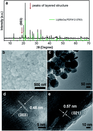
Fig. 1a shows the XRD pattern of the LMLNMC material. The majority of the X-ray diffraction peaks can be attributed to rhombohedral Li2MoO4 (JCPDS card no. 12-0768, space group R![[3 with combining macron]](https://www.rsc.org/images/entities/char_0033_0304.gif) , a = 14.34 Å, c = 9.59 Å). The characteristic (003) diffraction peak of typical LiMO2 layered structures could also be observed, which indicates the presence of LiNi0.4Mn0.4Co0.2O2 (red dashed arrows). Fig. 1b and c show the typical scanning electron microscopy (SEM) and transmission electron microscopy (TEM) images of the LMLNMCO after calcination. Both images show that the sample consists of nanoparticles with an average diameter of 100–200 nm. The smooth morphology also suggests that the composite forms a homogenous mixture during solid-state reaction. Fig. 1d and e show that the d-spacings from the HRTEM images are 0.48 nm and 0.57 nm, which can be well indexed with the (003) facets from the layered structure of LiNi0.4Mn0.4Co0.2O2 and (021) facets of rhombohedral Li2MoO4, respectively.
, a = 14.34 Å, c = 9.59 Å). The characteristic (003) diffraction peak of typical LiMO2 layered structures could also be observed, which indicates the presence of LiNi0.4Mn0.4Co0.2O2 (red dashed arrows). Fig. 1b and c show the typical scanning electron microscopy (SEM) and transmission electron microscopy (TEM) images of the LMLNMCO after calcination. Both images show that the sample consists of nanoparticles with an average diameter of 100–200 nm. The smooth morphology also suggests that the composite forms a homogenous mixture during solid-state reaction. Fig. 1d and e show that the d-spacings from the HRTEM images are 0.48 nm and 0.57 nm, which can be well indexed with the (003) facets from the layered structure of LiNi0.4Mn0.4Co0.2O2 and (021) facets of rhombohedral Li2MoO4, respectively.
 | ||
| Fig. 1 Morphological and structural characteristics of LMLNMC. (a) The XRD pattern; (b) SEM and (c) TEM images; (d) and (e) HRTEM images. | ||
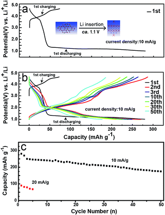
To address the electrochemical performance of LMLNMC, we investigated the charge and discharge profiles toward Li insertion/extraction. Coin-type cells with LMLNMCO as the cathode and Li metal as the anode were studied at a current density of 10 mA g−1 in the voltage range of 1.0–4.8 V (vs. Li+/Li). Fig. 2a and b show the charge/discharge profiles. In the first charge process, the composite LMLNMCO material shows a specific capacity of ca. 78 mA h g−1 from 3.0 to 4.5 V, which mainly corresponds to the contribution from LiNi0.4Mn0.4Co0.2O2. Meanwhile, during the first discharge process, in addition to the contribution from LiNi0.4Mn0.4Co0.2O2 (ca. 30 mA h g−1) from 4.5 V to 3.0 V, a long discharge plateau appeared at ca. 1.0 V (ca. 235 mA h g−1), which can be attributed to lithium insertion into Li2MoO4. However, in the following cycles, an obvious voltage slope appeared between 1.5 and 2.5 V, distinct from the first cycle, which probably implies that a structural change of Li2MoO4 appeared during the first lithium insertion process. The battery was also cycled at a current density of 10 mA g−1 in the voltage range of 1.0–4.8 V (vs. Li+/Li), and showed a capacity retention of about 61% after 50 cycles. The rate performance of this material was tested at 20 mA g−1 in the same voltage range, and compared with the results at 10 mA g−1, the charge and discharge capacity of this material decreased quickly from ca. 250 mA h g−1 to ca. 80 mA h g−1. This poor rate capability is similar to that observed for its Li2MnO3 analog, and still needs ongoing improvement for future applications.
 | ||
| Fig. 2 Electrochemical characterization of LMLNMCO. (a) and (b) Galvanostatic charge and discharge profiles; (c) cycle performance. | ||
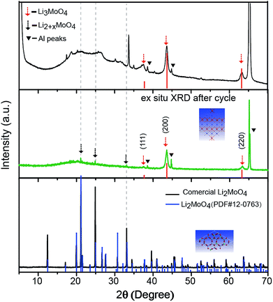
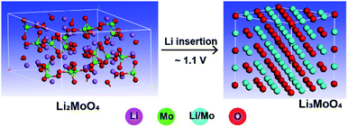
An ex situ X-ray diffraction experiment was carried out on commercial Li2MoO4 material and LMLNMCO to provide a general overview of the structure evolution of Li2MoO4 before and after lithium insertion. Fig. 3 shows the X-ray diffraction patterns. Commercial Li2MoO4 before lithium insertion shows a similar rhombohedral phase to LMLNMCO. However, an apparent structure change can be observed after lithium insertion. Two phases could be observed in Fig. 3. (1) An Li3MoO4 phase with a space group of Fm![[3 with combining macron]](https://www.rsc.org/images/entities/char_0033_0304.gif) m, similar to that of rocksalt-like NaCl structures, marked with dashed red arrows (Fig. 3, top); the peaks could be well indexed as (111), (200), and (220) of Li3MoO4, respectively. (2) Rhombohedral Li2+xMoO4, similar to Li2MoO4, but with a larger lattice.27 Scheme 1 illustrates the crystal structure change from Li2MoO4 to Li3MoO4 during lithium insertion, suggesting a structure change to a rock-salt structure, which is more similar to a layered structure and means that the structures are more likely to merge with each other. This structure change implies the instability of Li2MoO4 toward lithium insertion, but it provides the possibility of using an in situ electrochemical synthesis process to produce Mo4+-based lithium-rich composite electrode materials for future high-capacity lithium ion batteries.
m, similar to that of rocksalt-like NaCl structures, marked with dashed red arrows (Fig. 3, top); the peaks could be well indexed as (111), (200), and (220) of Li3MoO4, respectively. (2) Rhombohedral Li2+xMoO4, similar to Li2MoO4, but with a larger lattice.27 Scheme 1 illustrates the crystal structure change from Li2MoO4 to Li3MoO4 during lithium insertion, suggesting a structure change to a rock-salt structure, which is more similar to a layered structure and means that the structures are more likely to merge with each other. This structure change implies the instability of Li2MoO4 toward lithium insertion, but it provides the possibility of using an in situ electrochemical synthesis process to produce Mo4+-based lithium-rich composite electrode materials for future high-capacity lithium ion batteries.
Conclusions
In conclusion, a lithium-rich Li2MoO4·LiNi0.4Mn0.4Co0.2O2 composite material was obtained directly from high temperature solid-state reactions under an air atmosphere at 700 °C for 10 h. Li3MoO4 has a much higher lithium content than Li2MoO3 and the Mo4+/Mo6+ redox couple can exchange multiple electrons and provide more specific capacity. The material shows a high specific capacity and exhibits a high initial coulombic efficiency in our study. Additionally, we found that Li2MoO4 undergoes a phase change toward Li3MoO4 after lithium insertion at ca. 1.0 V. With this phase change, the Mo4+-based composite material is likely to be fabricated through an in situ electrochemical lithium insertion process. These advantages suggest that Li2MoO4 is a potential alternative for Li2MnO3. However, the cycling stability and rate performance of this material still need to be improved for future applications. The strategy here is simple yet very effective, and it may also be extended to other electrode materials for future high capacity Li-ion batteries used in electric vehicles and energy storage stations.Methods
Material synthesis
The Mo-based LMLNMC material was synthesized by a high-temperature solid-state reaction. Stoichiometric amounts of Li2MoO4, MnAc2·4H2O, NiAc2·4H2O, CoAc2·4H2O and LiOH·H2O were mixed together, ground in an agate mortar and then pressed into pellets. Each pellet was about 0.5 g, and the pellet was then heated in a muffle furnace at 700 °C for 10 h. The resulting material was stored in a glovebox under argon atmosphere to prevent reaction with moisture in the air. All the reactants were used as purchased.Electrochemical tests
Electrochemical tests were carried out in 2032 coin-type cells with an arrangement of Li|LiPF6 in EC![[thin space (1/6-em)]](https://www.rsc.org/images/entities/char_2009.gif) :
:![[thin space (1/6-em)]](https://www.rsc.org/images/entities/char_2009.gif) EMC
EMC![[thin space (1/6-em)]](https://www.rsc.org/images/entities/char_2009.gif) :
:![[thin space (1/6-em)]](https://www.rsc.org/images/entities/char_2009.gif) DEC (1
DEC (1![[thin space (1/6-em)]](https://www.rsc.org/images/entities/char_2009.gif) :
:![[thin space (1/6-em)]](https://www.rsc.org/images/entities/char_2009.gif) 1
1![[thin space (1/6-em)]](https://www.rsc.org/images/entities/char_2009.gif) :
:![[thin space (1/6-em)]](https://www.rsc.org/images/entities/char_2009.gif) 1, wt%)|LMO-LNMCO. The cells were assembled in an argon-filled glove box. To prepare the working electrode, LMO-LNMCO, Super-P, and PVDF (polyvinyl difluoride) were mixed at a weight ratio of 80
1, wt%)|LMO-LNMCO. The cells were assembled in an argon-filled glove box. To prepare the working electrode, LMO-LNMCO, Super-P, and PVDF (polyvinyl difluoride) were mixed at a weight ratio of 80![[thin space (1/6-em)]](https://www.rsc.org/images/entities/char_2009.gif) :
:![[thin space (1/6-em)]](https://www.rsc.org/images/entities/char_2009.gif) 10
10![[thin space (1/6-em)]](https://www.rsc.org/images/entities/char_2009.gif) :
:![[thin space (1/6-em)]](https://www.rsc.org/images/entities/char_2009.gif) 10 and ground in an agate mortar with a small volume of NMP (N-methyl-2-pyrrolidinone), and the obtained electrode slurry was then pasted on aluminum foil and dried in a vacuum oven at 100 °C after NMP was evaporated. The loading mass of active materials is about 2.5 mg cm−2. Pure lithium foil was used as a counter electrode. Celgard-2400 film was used as a separator. Galvanostatic charge and discharge tests were undertaken in the voltage range of 1.0–4.8 V (vs. Li+/Li) at a constant current density of 10 mA g−1. The specific capacities were calculated based on the mass of active materials.
10 and ground in an agate mortar with a small volume of NMP (N-methyl-2-pyrrolidinone), and the obtained electrode slurry was then pasted on aluminum foil and dried in a vacuum oven at 100 °C after NMP was evaporated. The loading mass of active materials is about 2.5 mg cm−2. Pure lithium foil was used as a counter electrode. Celgard-2400 film was used as a separator. Galvanostatic charge and discharge tests were undertaken in the voltage range of 1.0–4.8 V (vs. Li+/Li) at a constant current density of 10 mA g−1. The specific capacities were calculated based on the mass of active materials.
Structural characterization
The phase and crystallographic structure were characterized by powder X-ray diffraction (XRD) using a Bruker D8 Advanced diffractometer equipped with a Cu Kα1 (λ = 1.54056 Å) radiation source. An ex situ XRD method was used to characterize the structural evolution of Li2MoO4 and LMLNMCO after the electrochemical tests. The electrode foils after the test were removed from the coin-type cell, and washed with DMC solvent several times before being sealed on the sample stage for the XRD tests with Kapton film. All operations were carried out inside an argon-filled glove box to avoid side reactions with moisture in the air. The size and morphology of the samples were characterized using a JSM-6330F scanning electron microscope (SEM) operated at 10 kV. Transmission electron microscopy (TEM) and high-resolution TEM (HRTEM) microscopy were performed using a JEOL 2100F transmission electron microscope operated at an accelerating voltage of 200 kV.Conflicts of interest
There are no conflicts to declare.Acknowledgements
This work was financially supported by the National Natural Science Foundation of China (No. 21425627), the NFSC-SINOPEC Joint fund (No. U1663220), and the Natural Science Foundation of Guangdong Province (No. 2014A030308012).References
- M. S. Whittingham, Chem. Rev., 2014, 114, 11414–11443 CrossRef CAS PubMed.
- Y.-G. Guo, J.-S. Hu and L.-J. Wan, Adv. Mater., 2008, 20, 2878–2887 CrossRef CAS.
- K. Luo, M. R. Roberts, N. Guerrini, N. Tapia-Ruiz, R. Hao, F. Massel, D. M. Pickup, S. Ramos, Y.-S. Liu, J. Guo, A. V. Chadwick, L. C. Duda and P. G. Bruce, J. Am. Chem. Soc., 2016, 138, 11211–11218 CrossRef CAS PubMed.
- B. R. Long, J. R. Croy, J. S. Park, J. G. Wen, D. J. Miller and M. M. Thackeray, J. Electrochem. Soc., 2014, 161, A2160–A2167 CrossRef CAS.
- J. Bareño, C. H. Lei, J. G. Wen, S. H. Kang, I. Petrov and D. P. Abraham, Adv. Mater., 2010, 22, 1122–1127 CrossRef PubMed.
- M. Sathiya, G. Rousse, K. Ramesha, C. P. Laisa, H. Vezin, M. T. Sougrati, M. L. Doublet, D. Foix, D. Gonbeau, W. Walker, A. S. Prakash, M. Ben Hassine, L. Dupont and J. M. Tarascon, Nat. Mater., 2013, 12, 827–835 CrossRef CAS PubMed.
- M. M. Thackeray, C. S. Johnson, J. T. Vaughey, N. Li and S. A. Hackney, J. Mater. Chem., 2005, 15, 2257–2267 RSC.
- J. R. Croy, K. G. Gallagher, M. Balasubramanian, B. R. Long and M. M. Thackeray, J. Electrochem. Soc., 2014, 161, 9 CrossRef.
- J. Liu, J. Liu, R. Wang and Y. Xia, J. Electrochem. Soc., 2014, 161, A160–A167 CrossRef CAS.
- Y. Li, J. Bareno, M. Bettge and D. P. Abraham, J. Electrochem. Soc., 2015, 162, A155–A161 CrossRef CAS.
- L. Li, R. Jacobs, P. Gao, L. Gan, F. Wang, D. Morgan and S. Jin, J. Am. Chem. Soc., 2016, 138, 2838–2848 CrossRef CAS PubMed.
- Y. Koyama, I. Tanaka, M. Nagao and R. Kanno, J. Power Sources, 2009, 189, 798–801 CrossRef CAS.
- R. Xiao, H. Li and L. Chen, Chem. Mater., 2012, 24, 4242–4251 CrossRef CAS.
- S. Hy, F. Felix, J. Rick, W.-N. Su and B. J. Hwang, J. Am. Chem. Soc., 2014, 136, 999–1007 CrossRef CAS PubMed.
- F. Zheng, C. Yang, X. Xiong, J. Xiong, R. Hu, Y. Chen and M. Liu, Angew. Chem., Int. Ed., 2015, 54, 13058–13062 CrossRef CAS PubMed.
- J. Ma, Y.-N. Zhou, Y. Gao, Q. Kong, Z. Wang, X.-Q. Yang and L. Chen, Chem.–Eur. J., 2014, 20, 8723–8730 CrossRef CAS PubMed.
- Y. Gao, X. Wang, J. Ma, Z. Wang and L. Chen, Chem. Mater., 2015, 27, 3456–3461 CrossRef CAS.
- Y. Q. Wang, Z. Z. Yang, Y. M. Qian, L. Gu and H. S. Zhou, Adv. Mater., 2015, 27, 3915–3920 CrossRef CAS PubMed.
- X. Liu, Y. Lyu, Z. Zhang, H. Li, Y.-s. Hu, Z. Wang, Y. Zhao, Q. Kuang, Y. Dong, Z. Liang, Q. Fan and L. Chen, Nanoscale, 2014, 6, 13660–13667 RSC.
- K. S. Park, D. Im, A. Benayad, A. Dylla, K. J. Stevenson and J. B. Goodenough, Chem. Mater., 2012, 24, 2673–2683 CrossRef CAS.
- M. Zhang, G. Hu, L. Liang, Z. Peng, K. Du and Y. Cao, J. Alloys Compd., 2016, 673, 237–248 CrossRef CAS.
- D. Mikhailova, A. Sarapulova, A. Voss, A. Thomas, S. Oswald, W. Gruner, D. M. Trots, N. N. Bramnik and H. Ehrenberg, Chem. Mater., 2010, 22, 3165–3173 CrossRef CAS.
- J. Ma, Y. N. Zhou, Y. R. Gao, X. Q. Yu, Q. Y. Kong, L. Gu, Z. X. Wang, X. Q. Yang and L. Q. Chen, Chem. Mater., 2014, 26, 3256–3262 CrossRef CAS.
- M. Tian, Y. Gao, R. Xiao, Z. Wang and L. Chen, Phys. Chem. Chem. Phys., 2017, 19, 17538–17543 RSC.
- D. Li, H. He, X. Wu and M. Li, J. Alloys Compd., 2016, 682, 759–765 CrossRef CAS.
- J. Ma, Y. Gao, Z. Wang and L. Chen, J. Power Sources, 2014, 258, 314–320 CrossRef CAS.
- D. Li, H. Y. He, X. M. Wu and M. Q. Li, J. Alloys Compd., 2016, 682, 759–765 CrossRef CAS.
- D. Mikhailova, A. Voss, S. Oswald, A. A. Tsirlin, M. Schmidt, A. Senyshyn, J. Eckert and H. Ehrenberg, Chem. Mater., 2015, 27, 4485–4492 CrossRef CAS.
| This journal is © The Royal Society of Chemistry 2019 |


