 Open Access Article
Hydrated FePO4 nanoparticles supported on P-doped RGO show enhanced ORR activity compared to their dehydrated form in an alkaline medium†
Zubair Ahmeda,
Ritu Raia,
Rajinder Kumara,
Takahiro Maruyamab and
Vivek Bagchi *a
*a
aInstitute of Nano Science and Technology, Phase-10, Sector-64, Mohali, Punjab 160062, India. E-mail: vivekbagchi@gmail.com; bagchiv@inst.ac.in
bDepartment of Applied Chemistry, Meijo University, 1-501 Shiogamaguchi, Tempaku, Nagoya 468-8502, Japan
First published on 8th August 2019
Abstract
One-step hydrothermal growth of FePO4 nanoparticles (15–25 nm) uniformly decorated on the P-doped reduced graphene oxide (PRGO) was studied for oxygen reduction reaction (ORR) activity. The role of lattice water in the enhancement of catalytic activity in the hydrated FePO4·2H2O with respect to its dehydrated form in the alkaline medium was contested. The hydrodynamic LSV at 1600 rpm in alkaline medium (0.1 M KOH electrolyte) indicates an increase in the cathodic current density of the PRGO supported FePO4·2H2O catalyst, which reaches as high as 5.8 mA cm−2, close to the best known commercially available Pt/C catalyst. The stability in terms of retention of activity after 22![[thin space (1/6-em)]](https://www.rsc.org/images/entities/char_2009.gif) 000 s with the hydrated form was found to be 90.7% which is 26.7% higher than that of the dehydrated form.
000 s with the hydrated form was found to be 90.7% which is 26.7% higher than that of the dehydrated form.
Introduction
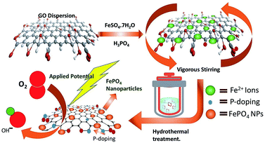
Overconsumption of fossil fuels and the various environmental issues have greatly motivated the scientific community towards the advancement of sustainable technologies specifically, fuel cells,1,2 metal–air batteries3–5 and solar cells.6–8 The advances in the field of fuel cell technology are mainly affected by the sluggish kinetics of the oxygen reduction reaction; therefore the development of a highly efficient catalyst for ORR is highly desirable. So far platinum and platinum group metals have emerged to be highly proficient catalysts for ORR. However, high cost, surface corrosion as well as methanol poisoning are some of the major flaws which deteriorate their practical applicability.9 Several attempts have been made to judiciously design non-nobel metal catalysts with performance similar to or better than Pt-based electrocatalysts, which include chalcogenides,10 transition metal oxides,11 carbides,12 phosphides13 and nitrides,14 as well as metal-free carbon-based materials.15 Owing to the high catalytic efficiency and stability, transition metal phosphates have gathered tremendous attention in recent years as they have the capability of influencing both the water oxidation as well as the electrocatalytic oxygen reduction. Several groups have found that the catalyst composed of Pt supported metal phosphates16,17 have shown superior ORR activity as compared to commercial Pt/C. Furthermore, metal-free, doped (B, S, N, P etc) carbonaceous materials have also shown their potential in the area of ORR catalysis18–22 as the introduction of heteroatoms into the graphite lattice not only enhances the conductivity but also provides strong support for holding the active sites.23–25 However, research efforts towards exploring the efficacy of metal phosphates as ORR catalysts are still limited.26 Thus the design and fabrication of highly efficient transition metal phosphates through a simple yet cost-effective methodology would provide a vision for a new class of catalytic materials for ORR. Herein we have used a one-pot hydrothermal method (as shown in Scheme 1) to synthesize FePO4 nanoparticles systematically grown on P-doped RGO and studied the ORR activities in the alkaline medium. To the best of our knowledge, the crucial role of lattice water of FePO4 in enhancing the catalytic activity, particularly for oxygen reduction electrocatalysis has never been explored.Experimental
Graphene nanoplatelets (<25 μm) were purchased from (TCI). Orthophosphoric acid (H3PO4), sulphuric acid (H2SO4) and potassium permanganate (KMnO4) were purchased from Merck. Graphene oxide was synthesized by an improved method27 using graphene nanoplatelets. The catalyst was synthesized by a one-step hydrothermal process. In brief, 0.2 mM (55 mg) of FeSO4·7H2O was added into the uniform dispersion of graphene oxide (1 mg ml−1) in distilled water with vigorous stirring. Orthophosphoric (1 ml of 3 M) acid was added dropwise with continuous stirring for 30 min. The reaction mixture was transferred into a stainless steel autoclave with Teflon vessel inside and kept at 180 °C for 12 h. The obtained product (FePH@PRGO) was washed with deionised water and further dried by heating it at 50 °C for 4 hours. The dehydrated product (FePD@PRGO) was obtained by annealing FePH@PRGO in argon at 300 °C for 30 minutes. A batch of P-doped RGO was synthesized by the same method for a comparative study.Characterization
The structural and morphological characterization were done using Eco D8 advance from Bruker, Cu Kα radiation with λ = 1.54 Å; Scanning Electron Microscope (JEOL JSM-IT300) was used for the morphological studies. Transmission electron microscopy using JEM-2100 TEM has been used at 200 kV to obtain the high-resolution TEM images. X-ray photoelectron spectroscopy (XPS, EscaLab: 220-IXL) was used to analyse the composition of the electrocatalyst by means of Mg-Kα non-monochromated X-ray beam having photon energy of 1253.6 eV. Surface area and pore size distribution were determined from N2 adsorption and desorption using (Autosorb-iQ) Quantachrome Instrument; thermogravimetric analysis was done using STA-8000 (Perkin Elmer); FTIR spectra were recorded on Carry 660 FTIR spectrometer.Electrochemical measurements
Electrochemical measurements were performed on an multichannel electrochemical workstation (Autolab PGSTAT 204M) equipped with electrode bipotentiostat system. Carbon electrode, Ag/AgCl (3 M KCl solution) and Rotating Ring Disk Electrode (RRDE) having a diameter of 5 mm were used as a counter, reference and working electrode respectively. The working electrode was coated with 10 μl of the catalyst ink which was prepared by dispersing 2 mg catalyst in 495 μl DMF and 5 μl of 5% Nafion. The catalyst coated electrode surface was dried in vacuum for overnight to get a uniform layer of material on the electrode surface. Cyclic voltammetry (CV) and linear sweep voltammetry (LSV) were performed in O2 saturated 0.1 M KOH by purging electrolyte with O2 30 min prior to electrochemical measurements. Several CV scanning was done with a scan rate of 50 mV −1 in the potential window of 0 to −1.0 V. LSV measurements were carried out in a potential window of 0.1 to −1 V with a scan rate of 10 mV s−1 on RRDE with rotating speed varying from 400 to 3000 rpm.Recently it has been revealed that the extensively used Koutechy–Levich (KL) method is not appropriate to evaluate “n” for the ORR studies.28 Hence, the rotating disk and ring-disk electrodes were analysed using convection methods for the calculation of the electron transfer number “n” for the oxygen reduction reaction (ORR) on the corresponding catalyst and the peroxide percentage was calculated using ring and disc current is given by eqn (1) and (2) respectively.
 | (1) |
 | (2) |
Results and discussion
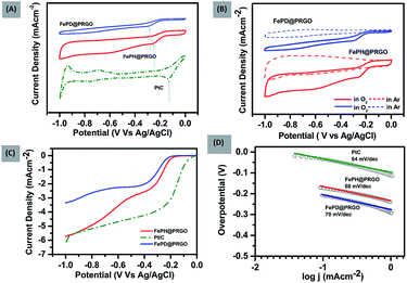
The FePO4 nanoparticles supported on P-doped RGO was synthesized both in hydrated (FePH@PRGO) and dehydrated form (FePD@PRGO) using the one-pot hydrothermal method. Here orthophosphoric acid (H3PO4) plays a bifunctional role as it facilitates the formation of phosphate nanoparticles and the incorporation of P atom in the graphitic lattice which in turn enhances the overall performance of the catalyst. Since the product obtained does not require any further purification thus holding the integrity of the process.The oxygen reduction activity of the catalysts was evaluated using CV studies carried out in O2 saturated 0.1 M KOH solutions for both FePD@PRGO and FePH@PRGO along with Pt/C shown in Fig. 1(A). The presence of prominent cathodic reduction peak in O2 saturated electrolyte as well as the absence of the same for both the catalyst in Ar saturated electrolyte reflects their activity for ORR Fig. 1(B). The cathodic reduction peak of O2 for FePH@PRGO as well as FePD@PRGO appears approximately at −0.24 V and −0.28 V respectively. Also, the FePH@PRGO catalyst outperforms by showing relatively higher current density (Fig. 1(A)). This observation directly indicates the crucial role of lattice water in facilitating ion transport. The superior catalytic activity of FePH@PRGO was also reflected in LSV measurements where the limiting current density reaches to −5.8 mA cm−2 with onset potential (−0.140 V) for FePH@PRGO which is very much close to Pt/C whereas, it reaches up to −3.4 mA cm−2 for FePD@PRGO (Fig. 1(C)). Furthermore, FePH@PRGO catalyst shows a smaller value of Tafel slope (68 mV dec−1) also reflects its efficacy for ORR catalysis (Fig. 1(D)).
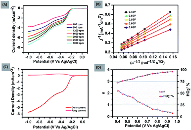
To further explore the kinetics and mechanistic aspects of ORR catalysis, LSV measurements of FePH@PRGO were performed at different rotations using RRDE, ranging from 400 to 3000 rpm shown in Fig. 2(A). Similar measurements were also done for FePD@PRGO and PRGO as shown in (ESI S1.1A and 2A†).
It was observed that limiting current density rises with an increase in rotational speed owing to the shortening of the diffusion distance in oxygen saturated electrolyte at high speed.29 The K–L (Koutechy–Levich) plots corresponding to the above mentioned LSV measurements are shown in Fig. 2(B) and (ESI S1.1B and 2B†). The occurrence of first-order kinetics for the reduction of dissolved oxygen is reflected by the K–L curves which are linear in nature at every potential.
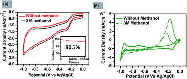
The number of electrons transferred (n) was calculated with the ring and disk plot Fig. 2(C) obtained at 1600 rpm and the value of n at different potentials (−0.40 to −0.95 V) was calculated to be in the range from ∼3.0–3.8. The corresponding ring and disk curve, suggests that the reaction is proceeding dominantly through a four-electron pathway for O2 reduction Fig. 2(D). The major challenges associated with the ORR electrocatalysts is methanol crossover effect which decreases the efficiency of fuel cell significantly and long term stability of the catalysts.30 The methanol poisoning of the catalyst was checked through cyclic voltammetry where 3 molar methanol is added to the electrolyte, FePH@PRGO shows high stability towards methanol oxidation with no significant change in CV curve whereas Pt/C, on the other hand, shows methanol oxidation and depressed the O2 reduction as shown in Fig. 3(A) and (B) respectively. The long term stability of electrocatalyst was further checked through (i–t) chronoamperometry measurements after 22![[thin space (1/6-em)]](https://www.rsc.org/images/entities/char_2009.gif) 000 s at −0.6 V with 1600 rpm under continuous oxygen flow. The catalyst was found to be quiet stable even after 22
000 s at −0.6 V with 1600 rpm under continuous oxygen flow. The catalyst was found to be quiet stable even after 22![[thin space (1/6-em)]](https://www.rsc.org/images/entities/char_2009.gif) 000 s with a slight decline of performance (−9.3%) shown in Fig. 3(A) inset. The dehydrated form was found to be less stable and is shown in ESI S1.1C.† All the values related to ORR activities were tabulated in ESI S2.†
000 s with a slight decline of performance (−9.3%) shown in Fig. 3(A) inset. The dehydrated form was found to be less stable and is shown in ESI S1.1C.† All the values related to ORR activities were tabulated in ESI S2.†
The composition of the catalysts, FePH@PRGO and FePD@PRGO were analysed using both PXRD and XPS. Typically, the peaks in the PXRD pattern (Fig. 4(A)) of FePH@PRGO can be indexed into a mixture of the monoclinic phase of FePO4·2H2O with space group P21/n and lattice parameters, a = 0.530 nm, b = 0.975 nm c = 0.867 nm (ref. 31) and of the tetragonal Fe1.37(PO4)(OH) phase with lattice parameter a = b = 0.519 nm and c = 1.299 nm and space group I41. High cyclic durability of the catalyst might be due to the lattice water present in FePH@PRGO catalyst. Annealing results in the formation of the catalyst FePD@PRGO with the later phase only.32
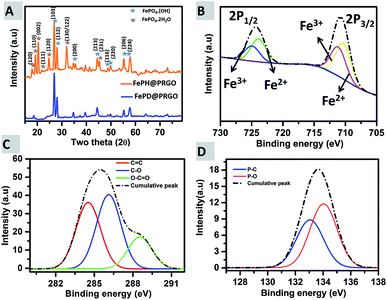 | ||
| Fig. 4 (A) PXRD showing the hydrated and dehydrated forms; FePH@PRGO & FePD@PRGO (B) high-resolution X-ray photoelectron spectra of Fe 2p, (C) showing the plot for C 1s, and (D) P 2p. | ||
In the XPS spectra Fig. 4(B) two prominent peaks at 711.08 eV and 725.08 eV, corresponding to Fe 2p3/2 and Fe 2p1/2, are present. The Fe 2p3/2 peak is comprising of two peaks at 710.2 eV (Fe2+) and 711.6 eV (Fe3+) and the Fe 2p1/2 can also be split into two peaks at 724 eV (Fe2+) and 725.8 eV (Fe3+) respectively. The deconvoluted P 2p spectrum (Fig. 4(C)) revealed two peaks positioned at 133.1 and 134.1 eV, which may be attributed to P–C and P–O bonding. In Fig. 4(D), the C 1s spectrum, the major peak at 284.5 eV was due to sp2 C–C bonding, whereas the peaks at 286.1 eV and 288.5 eV are resulting from C–O and O–C![[double bond, length as m-dash]](https://www.rsc.org/images/entities/char_e001.gif) O bonding. XPS survey spectra of FePH@PRGO was shown in ESI S3.† Thus both XPS and XRD successfully reveal the formation of FePO4 nanoparticles supported on P doped RGO.
O bonding. XPS survey spectra of FePH@PRGO was shown in ESI S3.† Thus both XPS and XRD successfully reveal the formation of FePO4 nanoparticles supported on P doped RGO.
Further, the qualitative, as well as quantitative analysis of lattice water, was done using FTIR and TGA. The presence of lattice water was qualitatively depicted from Fourier transmission spectroscopy where the strong stretching vibrations of H2O group at 3400 cm−1 are present in the spectra of FePH@PRGO whereas the peak at 3400 cm−1 reduced significantly in the dehydrated form as shown in Fig. 5(A).
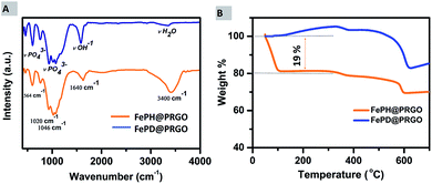 | ||
| Fig. 5 (A) FTIR spectra of FePH@PRGO and FePD@PRGO. (B) Thermogravimetric analysis curves of FePH@PRGO and FePD@PRGO under air atmosphere. | ||
A quantitative analysis of the amount of lattice water present in the FePH@PRGO catalyst was done using thermogravimetric analysis. TGA analysis was performed under aerobic environment in the temperature range of 50–700 °C. Fig. 5(B), shows a clear and sharp weight loss of approximately 19% depicted from the TGA curve may be correlated to the dehydration of FePO4·2H2O. The FePD@PRGO composite was obtained by annealing FePH@PRGO which results in partial reduction of Fe3+ to Fe2+ ions in the presence of carbon from PRGO.33 In oxidizing conditions the weight gain observed in FePD@PRGO at low temperature is possibly due to the partial oxidation of Fe2+ ions, resulting small weight gain (∼4.4%). The small weight loss during the temperature range of 300 to 500 °C is due to the slow decomposition of residual oxygen containing functional groups present on phosphorous doped reduced graphene oxide.34,35 The weight loss at higher temperature ranging between temperature 500–600 °C is majorly associated with rapid burning of the ring carbon in PRGO.36 However the higher amount of weight loss in FePD@PRGO is possibly due to the removal of OH bonds present in FePO4·OH (FePD@PRGO) which takes place in this temperature range.37 The observations obtained from N2 adsorption and desorption isotherm were also in line with the previous elucidations. The isotherm of both FePH@PRGO and FePD@PRGO are of “type IV” hysteresis curve shown in ESI Fig. S4A and B.† The surface area of FePD@PRGO comes out to be 185.20 m2 g−1 with an average pore size of 1.9 nm, whereas the surface area of FePH@PRGO is 55 m2 g−1 such a noticeable difference in the surface area can be explained due to the saturation of pores with the lattice water. In spite of high surface area, FePD@PRGO catalyst still struggles to exhibit good catalytic activity. Thus, it can undoubtedly be inferred that it is the lattice water which is playing a crucial role in enhancing the catalytic activity.
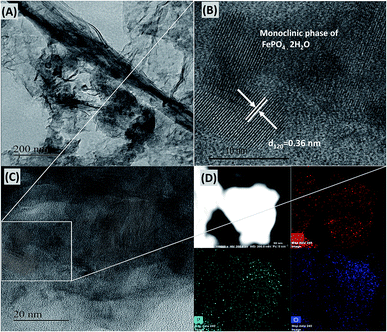
The structure and morphology of the FePH@PRGO catalyst were analysed using TEM shown in Fig. 6. Uniform nanoparticles of size ranging from 15–25 mm were distributed on the P doped graphite lattice. The inter-planar distance of 0.36 nm (Fig. 6(B)) was obtained which is consistent with the corresponding inter-planar distance of (120) plane in the monoclinic phase of FePO4·2H2O. The morphology of FePD@PRGO is shown in ESI S5.† The phosphorous doping in RGO was verified both qualitatively and quantitatively by elemental mapping and EDAX plot. The binding energy plot shows that P doping has taken place in RGO with an atomic percentage of 1.28% as shown in ESI S6.† The electrocatalyst after the stability measurement was recovered from the electrode surface for morphological studies. The TEM/HRTEM analysis was carried out to ensure the structural stability of the FePH@PRGO shown in ESI S7.†
Conclusions
Thus we conclude that non-noble metal based nanocomposite of FePO4 nanoparticles supported on P-doped RGO shows enhanced ORR activity compared to its dehydrated form. The study reveals that the lattice water in hydrated FePO4 catalyst plays a crucial role in enhancing the electrocatalytic oxygen reduction and provides extra stability to the catalyst in alkaline medium, which is relatively better than its dehydrated form obtained after annealing catalyst. This work highlights the role of water molecules present in the FePO4 crystal lattice in electrocatalytic ORR and unlocks a new horizon showing the possibilities of various low cost metal phosphates as catalyst in the fuel cell applications.Conflicts of interest
There are no conflicts to declare.Acknowledgements
VB appreciate the financial support from the Department of Science and Technology (DST) SB/FT/CS-021/2013 and EMR 000479 Project. Zubair acknowledges (DST) EMR 000479 for PhD fellowship and Centre for Nanoscience and Nanotechnology (CNSNT), Chandigarh for infrastructural support. RR and RK acknowledge INST for PhD fellowship.Notes and references
- W. Zhang, W. Lai and R. Cao, Chem. Rev., 2017, 117, 3717–3797 CrossRef CAS PubMed.
- D. Banham and S. Ye, ACS Energy Lett., 2017, 2, 629–638 CrossRef CAS.
- Z.-Q. Liu, H. Cheng, N. Li, T. Y. Ma and Y.-Z. Su, Adv. Mater., 2016, 28, 3777–3784 CrossRef CAS PubMed.
- J. Liu, C. Guan, C. Zhou, Z. Fan, Q. Ke, G. Zhang, C. Liu and J. Wang, Adv. Mater., 2016, 28, 8732–8739 CrossRef CAS PubMed.
- S. S. Shinde, C. H. Lee, J.-Y. Yu, D.-H. Kim, S. U. Lee and J.-H. Lee, ACS Nano, 2018, 12, 596–608 CrossRef CAS PubMed.
- D. Zhao, C. Chen, C. Wang, M. M. Junda, Z. Song, C. R. Grice, Y. Yu, C. Li, B. Subedi, N. J. Podraza, X. Zhao, G. Fang, R.-G. Xiong, K. Zhu and Y. Yan, Nat. Energy, 2018, 3, 1093–1100 CrossRef CAS.
- E. Kabir, P. Kumar, S. Kumar, A. A. Adelodun and K.-H. Kim, Renewable Sustainable Energy Rev., 2018, 82, 894–900 CrossRef.
- J. Hou, O. Inganäs, R. H. Friend and F. Gao, Nat. Mater., 2018, 17, 119 CrossRef CAS PubMed.
- H. Tang, J. Luo, X. L. Tian, Y. Dong, J. Li, M. Liu, L. Liu, H. Song and S. Liao, ACS Appl. Mater. Interfaces, 2018, 10, 11604–11612 CrossRef CAS PubMed.
- Y. Tang, T. Chen, W. Guo, S. Chen, Y. Li, J. Song, L. Chang, S. Mu, Y. Zhao and F. Gao, J. Power Sources, 2017, 362, 1–9 CrossRef CAS.
- Y.-Q. Lyu, C. Chen, Y. Gao, M. Saccoccio and F. Ciucci, J. Mater. Chem. A, 2016, 4, 19147–19153 RSC.
- T. Huang, S. Mao, H. Pu, Z. Wen, X. Huang, S. Ci and J. Chen, J. Mater. Chem. A, 2013, 1, 13404–13410 RSC.
- C. Han, X. Bo, Y. Zhang, M. Li, A. Wang and L. Guo, Chem. Commun., 2015, 51, 15015–15018 RSC.
- Y. Dong and J. Li, Chem. Commun., 2015, 51, 572–575 RSC.
- Y. Dong, Y. Deng, J. Zeng, H. Song and S. Liao, J. Mater. Chem. A, 2017, 5, 5829–5837 RSC.
- C. Kim, B. Lee, Y. Park, B. Park, J. Lee and H. Kim, Appl. Phys. Lett., 2007, 91, 113101 CrossRef.
- P. J. Bouwman, W. Dmowski, J. Stanley, G. B. Cotten and K. E. Swider-Lyons, J. Electrochem. Soc., 2004, 151, A1989–A1998 CrossRef CAS.
- L. Yang, S. Jiang, Y. Zhao, L. Zhu, S. Chen, X. Wang, Q. Wu, J. Ma, Y. Ma and Z. Hu, Angew. Chem., Int. Ed., 2011, 50, 7132–7135 CrossRef CAS PubMed.
- Z. Yang, Z. Yao, G. Li, G. Fang, H. Nie, Z. Liu, X. Zhou, X. A. Chen and S. Huang, ACS Nano, 2011, 6, 205–211 CrossRef CAS PubMed.
- K. Gong, F. Du, Z. Xia, M. Durstock and L. Dai, science, 2009, 323, 760–764 CrossRef CAS PubMed.
- J. Zhu, M. Xiao, P. Song, J. Fu, Z. Jin, L. Ma, J. Ge, C. Liu, Z. Chen and W. Xing, Nano Energy, 2018, 49, 23–30 CrossRef CAS.
- I. Y. Jeon, S. Zhang, L. Zhang, H. J. Choi, J. M. Seo, Z. Xia, L. Dai and J. B. Baek, Adv. Mater., 2013, 25, 6138–6145 CrossRef CAS PubMed.
- H. Cui, Z. Zhou and D. Jia, Mater. Horiz., 2017, 4, 7–19 RSC.
- C. Tang and Q. Zhang, Adv. Mater., 2017, 29, 1604103 CrossRef PubMed.
- J. Jin, F. Pan, L. Jiang, X. Fu, A. Liang, Z. Wei, J. Zhang and G. Sun, ACS Nano, 2014, 8, 3313–3321 CrossRef CAS PubMed.
- M. Pramanik, C. Li, Y. V. Kaneti and Y. Yamauchi, Chem. Commun., 2017, 53, 5721–5724 RSC.
- D. C. Marcano, D. V. Kosynkin, J. M. Berlin, A. Sinitskii, Z. Sun, A. Slesarev, L. B. Alemany, W. Lu and J. M. Tour, ACS Nano, 2010, 4, 4806–4814 CrossRef CAS PubMed.
- R. Zhou, Y. Zheng, M. Jaroniec and S.-Z. Qiao, ACS Catal., 2016, 6, 4720–4728 CrossRef CAS.
- W. Y. Xing, G. Yin, J. Zhang, Rotating Electrode Methods and Oxygen Reduction Electrocatalysts, Elsevier, Amsterdam, 2014 Search PubMed.
- Y. Shao, G. Yin and Y. Gao, J. Power Sources, 2007, 171, 558–566 CrossRef CAS.
- K. Zaghib and C. Julien, J. Power Sources, 2005, 142, 279–284 CrossRef CAS.
- Y. Song, P. Y. Zavalij, N. A. Chernova and M. S. Whittingham, Chem. Mater., 2005, 17, 1139–1147 CrossRef CAS.
- Y. Wang, M.-Q. Wang, L.-L. Lei, Z.-Y. Chen, Y.-S. Liu and S.-J. Bao, Microchim. Acta, 2018, 185, 140 CrossRef PubMed.
- R. Doufnoune and N. Haddaoui, J. Polym. Res., 2017, 24, 138 CrossRef.
- K. Liu, L. Chen, Y. Chen, J. Wu, W. Zhang, F. Chen and Q. Fu, J. Mater. Chem., 2011, 21, 8612–8617 RSC.
- S. Thakur and N. Karak, Carbon, 2012, 50, 5331–5339 CrossRef CAS.
- H.-C. Liu, W.-H. Ho, C.-F. Li and S.-K. Yen, J. Electrochem. Soc., 2008, 155, E178–E182 CrossRef CAS.
Footnote |
| † Electronic supplementary information (ESI) available. See DOI: 10.1039/c9ra04070f |
| This journal is © The Royal Society of Chemistry 2019 |

