 Open Access Article
rGO/Fe3O4 hybrid induced ultra-efficient EMI shielding performance of phenolic-based carbon foam
Kejing Yu a,
Yao Zenga,
Guilong Wang
 *b,
Xia Luoa,
Tingting Lib,
Jinchuan Zhaoc,
Kun Qian*a and
Chul B. Park
 *c
*c
aKey Laboratory of Eco-Textiles, Ministry of Education, Jiangnan University, Wuxi, Jiangsu 214122, China. E-mail: qiankun_8@163.com
bKey Laboratory for Liquid-Solid Structural Evolution and Processing of Materials (Ministry of Education), Shandong University, Jinan, Shandong 250061, China. E-mail: guilong@sdu.edu.cn
cMicrocellular Plastics Manufacturing Laboratory, Department of Mechanical and Industrial Engineering, University of Toronto, Toronto, Ontario M5S 3G8, Canada. E-mail: park@mie.utoronto.ca
First published on 2nd July 2019
Abstract
To develop high-performance electromagnetic interference (EMI) shielding materials is crucial to solving the growing problem of electromagnetic pollution. Herein, we report a facile way to fabricate reduced graphene oxide/Fe3O4 (rGO/Fe3O4) hybrid-modified carbon foams for EMI shielding applications. The rGO/Fe3O4 was firstly synthesized via a co-precipitation method, and it was then mixed with phenol to prepare rGO/Fe3O4 hybrid-modified phenolic foam. The phenolic foam was further used as the precursor to fabricate rGO/Fe3O4 hybrid-modified carbon foam by carbonization. The fabricated rGO/Fe3O4 hybrid-modified carbon foam showed outstanding EMI shielding performance. The 1.5 wt% rGO/Fe3O4-modified carbon foam with a thickness of 3 mm exhibited an EMI shielding effectiveness (SE) of up to 63.5 dB at the X-band frequency range. In terms of specific EMI SE, these phenolic-based carbon foams with the rGO/Fe3O4 hybrid exhibited rather superior performance compared to the regular EMI shielding materials such as metals and conductive polymer composites (CPC). Furthermore, the rGO/Fe3O4 hybrid-modified carbon foam showed improved compressive mechanical properties compared with the virgin or rGO-modified carbon foam. Thus, the phenolic-based carbon foam modified with the rGO/Fe3O4 hybrid showed a promising future in many advanced applications where both EMI shielding and light weight are required.
1 Introduction
In recent years, the growing use of electronic devices has driven the problem of electromagnetic pollution, which not only affects the normal functionality of electronic devices and equipment,1 but also creates potential risks to the health of human beings.2 Thus, it is of great significance to develop high-performance electromagnetic interference (EMI) shielding materials to solve the problem of electromagnetic pollution.3,4Carbon foam is an ideal electromagnetic shielding material due to many superiorities.5 Compared with the regular metal-based or conductive polymer composite-based EMI shielding materials, carbon foam possesses many advantages such as outstanding EMI shielding performance, super anti-corrosion, excellent high-temperature resistance, and ultra-low density.6,7 It was reported that the carbon foam with a thickness of 1 mm showed an EMI shielding effectiveness (SE) value of about 20 dB in the frequency band 1–4 GHz.8 Yuan et al. prepared a multifunctional stiff carbon foam derived from bread, and the carbon foam with a density of 0.29 g cm−3 and a thickness of 3 mm exhibited an EMI SE value of about 15.6 dB in the frequency band 6–13 GHz.9 Zhang et al. fabricated a carbon foam with a density of 0.15 g cm−3 by carbonizing phthalonitrile (PN)-based polymer foam, which had an EMI SE value of approximately 51.2 dB over the frequency range of 8.2 to 12.4 GHz under the thickness of 2.0 mm.10
The phenolic foam with closed-cell structure is an excellent precursor for the fabrication of carbon foams due to the following advantages. First, the phenolic molecule contains a large number of benzenes with the unique chemical structure of two benzene ring and single methylene. Thus, the phenolic foam has a high carbon content, high atom bond energy, and high molecular chain cohesive energy. All of these factors lead to a high carbon residue and high structure intensity when fabricating carbon foams by carbonization of phenolic foams.11 Second, the phenolic foam shows excellent flame resistance, and has low generation of toxic gases during pyrolysis. Thus, it shows little impact on the environment during carbonization of phenolic foams. Third, the carbon foam's structure can be easily tailored in a wide range by manipulating phenolic resins and tuning foaming conditions.12–14 As a consequence, the carbon foam's properties can be well controlled. The last but not least, the fabrication of phenolic foam is currently very mature, cost-effective and scalable.15,16
Adding electrically conductive or magnetic additives into carbon foam is an effective way to enhance its electromagnetic shielding performance, because these additives can have a strong interaction either with the electric component or with the magnetic component of electromagnetic waves.17,18 It was reported that Ni/carbon foam exhibited greatly enhanced microwave absorption ability compared with the virgin carbon foam.19 Xiao et al. developed the amorphous carbon foam nanostructured by SiC nanowires, and achieved a reflection loss value of 31 dB over the frequency band from 8.2 GHz to 12.4 GHz under an optimum thickness of 3.3 mm.20 Rajeev et al. found that nano-sized iron particles can act as catalysts in improving the graphitization of carbon foams, and thus enhance the carbon foam's electrical conductivity and EMI shielding performance. Adding 10 wt% of ferrocene into carbon foam led to a specific SE of 130 dB cm3 g−1, which was the highest value at that time.21
Towards developing lightweight materials for ultra-efficient EMI shielding applications, herein we studied the fabrication of closed-cell carbon foam with the phenolic foam as precursor. To further improve the EMI shielding performance of carbon foam, the rGO/Fe3O4 hybrid was introduced into the carbon foam through an in situ way. TEM, FTIR and XRD were employed to characterize the structure of rGO/Fe3O4 hybrid nanocomposite. SEM was used to observe the cellular structure of the carbon foams, based on which the role of the hybrid nanocomposite on foaming was discussed. Moreover, a vector network analyzer was employed to measure the EMI shielding properties of the carbon foams. It is found that the rGO/Fe3O4 hybrid nanocomposite can dramatically enhance the EMI shielding performance of the carbon foams, and the EMI shielding mechanism was analyzed. The 3.0 mm thick carbon foam modified with 1.5 wt% rGO/Fe3O4 exhibits an specific EMI SE value of up to 4062 dB cm3 g−1, which, to our knowledge, is the highest value achieved so far. Thus, it shows a promising future in many areas such as aerospace and electronics industries as an advanced EMI shielding material, especially considering its facile fabrication strategy.
2 Materials and experiment
2.1 Materials
Graphene nanoplates (GNPs, 1 to 20 μm in diameter; 5 to 15 nm in thickness) were supplied by Xiamen Kona Graphene Technology Co. Ltd., China. Phenol, formaldehyde (37 wt%), FeCl2·4H2O, FeCl3·6H2O, NaOH, NaBH4, Tween-80 (surfactant agent), n-pentane (foaming agent) and toluenesulfonic acid (curing agent) were all purchased from Sinopharm Chemical Reagent Co. Ltd, China.2.2 Preparation of rGO/Fe3O4 hybrid materials
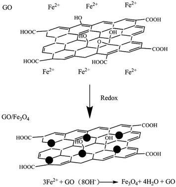
Graphene oxide (GO) was prepared by the mixture acid oxidization (H2SO4 and HNO3) method. In a representative procedure, GNPs (900 mg) were suspended and refluxed in a mixture of concentrated acid H2SO4/HNO3 (30 ml/30 ml) at 140 °C for 1 h, followed by diluting with deionized water (3000 ml). Afterwards, the acid-treated GNPs were retrieved and washed repeatedly with tetrahydrofuran (THF) until pH = 7, and then dried under vacuum to obtain GO. More details about the preparation of GO are available in our previous work.22 As Fig. 1 shows, the GO/Fe3O4 was synthesized via a co-precipitation method. Firstly, GO (200 mg), FeCl3·6H2O (176 mg), and FeCl2·4H2O (130 mg) were dissolved in 250 mg deionized water under N2 atmosphere. Afterwards, the mixture with a pH value of 11 was mechanically stirred at 80 °C for 2 h. Subsequently, 300 mg NaBH4 was added into the mixture, which was followed by another 1 h stirring at 80 °C. Then, the reaction mixture was cooled down slowly to room temperature. Finally, the obtained suspension was washed five times with ethanol, and then dried at 80 °C in vacuum to obtain rGO/Fe3O4 hybrid. Under the above formulations and conditions, the weight fraction of Fe3O4 in the hybrid is in the range from 45% to 50%.2.3 Preparation of hybrid materials/phenolic carbon foam composites
At first, rGO/Fe3O4 (0.5 wt%, 1 wt%, 1.5 wt%) was dispersed into phenol (94 g) under stirring at 2000 r/min for 30 min. Then, the suspension was mixed with paraformaldehyde (56 g) and NaOH (10 g) under rapid stirring at 90 °C for 4 h. Afterwards, the hydrochloric acid was added into the mixture until the pH value of mixture reduced to 7. Subsequently, the neutral mixture was distilled under 0.05 MPa at 80 °C to remove the superfluous water. Next, the obtained suspension of phenolic resin and rGO/Fe3O4 hybrid composite (50 g) was mixed with n-pentane (6 g), Tween-80 (1 g), and toluenesulfonic acid (7 g) under stirring at 2000 rpm for 3 min. Hereafter, the mixture was poured into a mold at 80 °C for 1 h to fabricate the rGO/Fe3O4 hybrid-modified phenolic foam. Finally, the phenolic foam was carbonized at 800 °C to obtain the rGO/Fe3O4 hybrid-modified carbon foam.2.4 Characterizations
Fourier transform infrared spectroscopy (FTIR, Nexus 670, Valencia, USA) was employed to detect the functional groups on the surface of graphene, GO, and rGO/Fe3O4 hybrid. X-ray diffraction (XRD) analysis of GO and rGO/Fe3O4 was performed using a Bruker D8 venture PRO expert diffractometer (Bruker Co., Germany) at room temperature with nickel-filtered Cu Kα radiations as X-ray source, operating at a voltage of 40 kV and a current of 30 mA. A Raman spectroscope (JY Labram HR 800 spectrometer), excited by 632.8 nm He–Ne laser, was used to analyze the microstructure of GO and rGO/Fe3O4 hybrid.A transmission electron microscopy (TEM, H-800-1, Japan) was used to observe the microstructure of nanoparticles. A scanning electron microscopy (SEM, HITACHI SU1510, Japan) was employed to observe the cellular structure of foams. The cell size and its distribution of foams were measured based on the SEM images by using the Nano Measurer software. The cell size was acquired by measuring at least 200 cells, and the average value of cell size was reported. Moreover, the water-displacement method based on Archimedes' principle was employed to measure foam density according to ASTM D792-00.
A vector network analyzer (Agilent, N5247A) equipped with a scattering parameter (S-parameter) test was used to characterize the EMI shielding effectiveness (SE) of the foams over a frequency range of 8–12 GHz. When an electromagnetic wave incidents on a sample, the incident energy will be basically divided into three components: reflection, absorption, and transmission. The EMI SE is defined as the logarithmic ratio of incident energy to the transmission energy. Thus, both reflection and absorption contribute to the EMI shielding performance of the sample. Notably, compared with reflection, absorption is much more preferred for EMI shielding materials, because absorption can completely solve the problem of electromagnetic pollution whereas the reflected electromagnetic waves produce secondary electromagnetic pollutions. The total SE as well as shielding by absorption and reflection can thus be calculated using the following formulas:23
 | (1) |
SEA (dB) = 10![[thin space (1/6-em)]](https://www.rsc.org/images/entities/char_2009.gif) log[(1 − R)/T] log[(1 − R)/T]
| (2) |
SEA (dB) = 10![[thin space (1/6-em)]](https://www.rsc.org/images/entities/char_2009.gif) log[1/(1 − R)] log[1/(1 − R)]
| (3) |
| R = |S11|2, T = |S21|2 | (4) |
An Alpha-A™ high-performance conductivity analyzer, manufactured by Novocontrol Technologies, Germany, was employed to measure the carbon foam's electrical conductivity. To prepare the sample for measurement, the fabricated carbon foam was cut into a disk shape with a diameter of 20 mm and a thickness of 2.0 mm. To avoid the contact resistance effect, both the upper and lower contact surfaces of the sample were coated with a thin layer of gold. In all cases, a voltage of 1.0 V was applied. The measured electrical conductivity at a low frequency of 0.01 Hz was taken as the DC conductivity. At least three sample replications were performed in each case, and the average values were reported.
To check the mechanical properties of foams, a computer-controlled material testing system (4206, INSTRON, USA) was used to perform compression tests. The test sample was prepared according to the standard of ASTM D1621-2010, and the crosshead speed in tests was 2.5 mm min−1. To prepare the sample for tests, foams were cut into a regular hexahedron shape with dimensions of 50 mm × 25 mm × 25 mm.
3 Result and discussion
3.1 Fourier transform infrared spectroscopy (FTIR)
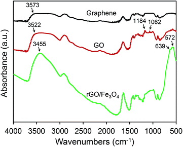
Fig. 2 shows the FTIR analysis results of graphene, GO, and rGO/Fe3O4 hybrid. Compared with graphene, two unique characteristic absorption peaks at 1184 cm−1 and 1062 cm−1 are observed for GO. It clearly demonstrates that the formation of C![[double bond, length as m-dash]](https://www.rsc.org/images/entities/char_e001.gif) O group due to the oxidation of graphene in the solution with HNO3 and H2SO4. Moreover, the remarkably enhanced absorption group at approximately 3500 cm−1 also indicates the formation of GO after oxidation because it is common that there are many hydroxyl groups on the surface of GO. Regarding the FTIR pattern of rGO/Fe3O4, there are two unique characteristic absorption peaks at 572 cm−1 and 639 cm−1, and they are correlated to the stretching vibrations of Fe–O group. It indicates that the rGO/Fe3O4 hybrid nanocomposite has been successfully constructed.
O group due to the oxidation of graphene in the solution with HNO3 and H2SO4. Moreover, the remarkably enhanced absorption group at approximately 3500 cm−1 also indicates the formation of GO after oxidation because it is common that there are many hydroxyl groups on the surface of GO. Regarding the FTIR pattern of rGO/Fe3O4, there are two unique characteristic absorption peaks at 572 cm−1 and 639 cm−1, and they are correlated to the stretching vibrations of Fe–O group. It indicates that the rGO/Fe3O4 hybrid nanocomposite has been successfully constructed.
3.2 XRD patterns
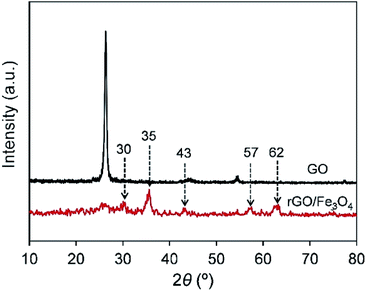
Fig. 3 presents the XRD patterns of graphene oxide and rGO/Fe3O4 hybrid. From the XRD pattern of graphene oxide, the dominant characteristic peak of graphene oxide is observed at 26° which correlates to the (002) plane of the graphite structure. The sharp peak at 26° reflects the well-ordered GO layers. For the XRD spectrum of rGO/Fe3O4, the characteristic peak of GO declines significantly, and it indicates that the introduction of Fe3O4 destroys the order arrangement of GO layers. New peaks appear at about 30°, 35°, 43°, 57°, 62° are attributed to the characteristic peaks of the Fe3O4, and they respectively correspond to the (220), (311), (400), (422), (511), and (440) planes of single Fe3O4 crystal. Combined with the FTIR analysis results, it fully confirms that the Fe3O4 has been grafted onto the surface of the reduced graphene oxide through the in situ preparation treatment.3.3 Raman spectra analysis
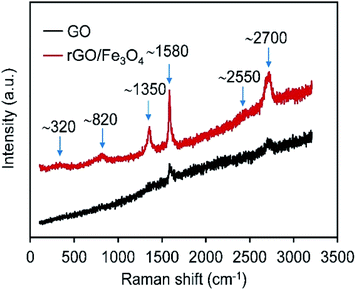
Raman spectroscopy affords a non-destructive technique in the study of the bonding nature of the hybrid. Fig. 4 shows the recorded Raman spectrums of GO and rGO/Fe3O4 hybrid. The Raman spectrum of GO shows bands at ∼1580, ∼2550, and ∼2700 cm−1, known as G, G*, and 2D bands, respectively.24 The G-band corresponds to the first-order scattering of the E2g mode observed for sp2 carbon domains, whereas the D-band is due to phonon branches around the K point and caused by structural effects or edges that can break the symmetry and selection rule. The lack of the trace of the disorder-induced D band at ∼1350 cm−1 indicates the high quality of graphene oxide.24,25 After incorporation with Fe3O4 nanoparticles, another two bands at ∼320 and ∼820 cm−1 appear. Those bands are typical Raman peaks of Fe3O4, which can be assigned to Eg and A1g mode of Fe3O4.26,27 It further confirms that the rGO/Fe3O4 hybrid has been constructed.3.4 Morphology analysis
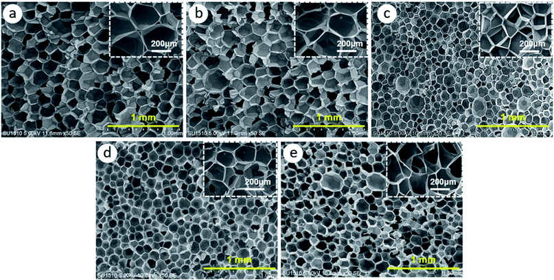
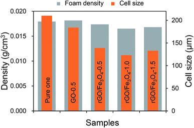
Fig. 5 presents the TEM morphology of the GO and rGO/Fe3O4 hybrid. It can be seen in Fig. 5a that the GO surface is smooth and free from any particulate contamination. After treatment, it can be clearly seen that Fe3O4 particles with a mean size of 5–10 nm have been grafted onto the surface of GO, and thus rGO/Fe3O4 hybrid with a three-dimensional structure has been constructed.Fig. 6 shows the cellular morphology of the fabricated carbon foams. It can be observed that all carbon foams present a uniform closed-cell structure. Notably, the introduction of 0.5 wt% rGO shows little effect on the cellular structure, whereas the introduction of 0.5 wt% rGO/Fe3O4 hybrid dramatically refines the cellular structure, as Fig. 7 shows. Specifically, the cell size is reduced from about 200 μm to about 130 μm while the cell density is decreased from 0.018 to 0.016 g cm−3 by introducing rGO/Fe3O4 hybrid. However, the cellular morphology does not show further improvement by adding more rGO/Fe3O4 hybrid.
According to the heterogeneous cell nucleation theory, additives can create a large amount of interfaces which help to promote cell nucleation by reducing cell nucleation energy barrier.28,29 Generally, the larger the interface area is, the higher the cell nucleation density is. As rGO/Fe3O4 hybrid nanocomposites definitely create much more interfaces than GO, the rGO/Fe3O4 hybrid-modified carbon foam thus shows rather refined cellular structure than the GO-modified carbon foam. With more rGO/Fe3O4 hybrid nanocomposites are added, they tend to agglomerate and hence the nucleation sites might not increase significantly. Therefore, the cell density does not increases continuously by further adding GO/Fe3O4 hybrid.
3.5 Electromagnetic shielding effectiveness of the phenolic carbon foam
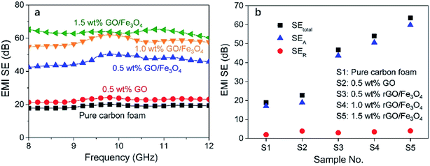
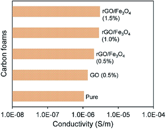
Fig. 8a shows the measured EMI SE of the fabricated carbon foams over the X-band frequency range. It is observed that even the pure carbon foam performs a good EMI shielding capacity with an average EMI SE of about 19 dB over the whole X-band range. This can be owing to the fact that the carbon element has a strong interaction with the electromagnetic wave over the full X-band frequency range. Moreover, the porous structure of the carbon foam creates many interfaces which greatly enhance multi-reflections and multi-absorptions of electromagnetic waves.30By introducing 0.5 wt% rGO into carbon foam, it is found that the EMI SE just shows a little increment of about 2 dB. Since graphene after oxidation has become a poorly conductive material, such small amount of rGO does not show any obvious effects in blocking the electromagnetic waves compared with the carbon matrix. Fig. 9 shows the measured electrical conductivity of the carbon foams. It can be seen that all the carbon foams show a similar level of electrical conductivity. However, it is surprising to find that the EMI SE of the carbon foam is dramatically increased to higher than 45 dB by introducing an extremely small amount of Fe3O4, and its value further increases up to 65 dB as the concentration of rGO/Fe3O4 rises to 1.5 wt%, as Fig. 8b shows. The sharply enhanced EMI shielding performance is owing to the fact that Fe3O4 is a magnetic material which has a strong interaction with the magnetic component of electromagnetic wave, and thus it can significantly attenuate electromagnetic waves. It has been demonstrated in previous literature that the addition of Fe3O4 that has strong magnetic properties could contribute to the hysteresis and dielectric loss for electromagnetic waves, thus leading to improved attenuation of the electromagnetic waves.31,32 In addition, the slightly increased electrical conductivity, as shown in Fig. 9, could contribute to both reflection and absorption of electromagnetic waves, and hence enhance EMI shielding properties.
From Fig. 8b, it is worth noting that SER is only several dB, which is far smaller than SEA for all the carbon foams. It indicates that the shielding by absorption is the dominant attenuation mechanism all the carbon foams. The presence of Fe3O4 leads to the dramatically increased SEA and shows little effect on SER. It indicates the shielding mechanism of Fe3O4 is absorption because Fe3O4 shows strong interaction with the magnetic component of electromagnetic waves. Moreover, it is believed that the porous structure of carbon foams contributed to the absorption-dominated shielding behaviour due to multi reflection and absorption of electromagnetic waves.33–35 Compared with the typical reflection-dominated EMI shielding behavior presented by the common EMI shielding materials such as metals and solid CPCs, this absorption-dominated EMI shielding feature exhibits superiority in actual EMI shielding applications because reflections can affect the functionality and even cause damage to other electronic circuits or components.36
In many areas such as aerospace and electronics industries, lightweight is a critical issue that should be considered when choosing EMI shielding materials. Thus, the specific EMI SE, defined as the ratio of the EMI SE to the density, is a more appropriate criterion to compare the EMI shielding performance for the applications where lightweight is required.37,38 It is worth noting that all the fabricated carbon foams have very low densities in the range from 0.016 g cm−3 to 0.02 g cm−3, as plotted in Fig. 7. Thus, these carbon foams show outstanding specific EMI shielding performance. In particular, the carbon foam modified with 1.5 wt% rGO/Fe3O4 has a specific EMI SE value of as high as 4062 dB cm3 g−1, which, to our knowledge, is the highest value achieved so far.39–41
3.6 Mechanical properties of phenolic foams composites
Fig. 10 shows the compressive strength and modulus of the fabricated carbon foams. Overall, it can be clearly seen that the compressive mechanical properties of the carbon foams are significantly improved by adding GO or rGO/Fe3O4 hybrid. Notably, rGO/Fe3O4 hybrid is more effective in improving the mechanical performance than GO. It is naturally easy to understand as the rGO/Fe3O4 hybrid with a three-dimensional structure generally shows better rigidity than the GO with a two-dimensional structure.42,43 Moreover, the smaller cell size of the rGO/Fe3O4 hybrid-modified carbon foam also contributes to its higher compressive properties according to the mechanical model developed by Gibson and Ashby.44 As the GO/Fe3O4 concentration rises from 1.0 wt% to 1.5 wt%, both the compressive strength and modulus reduce significantly, as Fig. 10b shows. This phenomenon can be owing to the agglomeration of nano-sized rGO/Fe3O4 hybrid at high concentrations.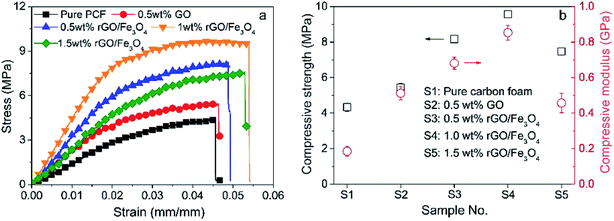 | ||
| Fig. 10 The compressive mechanical properties of the carbon foams: (a) stress–strain curves, and (b) compressive strength and modulus. | ||
4 Conclusion
In summary, we reported a facile and flexible strategy to prepare the hybrid GO/Fe3O4 hybrid-modified carbon foams for ultra-efficient EMI shielding applications. The rGO/Fe3O4 hybrid-modified carbon foam shows much better EMI shielding performance than the virgin carbon foam or the GO-modified carbon foam. For instance, both the virgin and GO-modified carbon foams have an EMI SE value of about 20 dB while the carbon foam modified with merely 0.5 wt% rGO/Fe3O4 has an EMI SE value of up to 45 dB. As the rGO/Fe3O4 concentration increases to 1.5 wt%, the carbon foam's EMI SE value can rise up to 65 dB, which means more than 99.9999% electromagnetic radiation waves are blocked. More importantly, the density of the rGO/Fe3O4 hybrid-modified carbon foam is merely 0.016 g cm−3, and hence its specific EMI SE value is as high as 4062 dB cm3 g−1, which, to our knowledge, is the best value reported so far. This outstanding EMI shielding performance is owing to the strong ferromagnetic properties of Fe3O4 combined with the conductive properties of carbon foam matrix. Moreover, the rGO/Fe3O4 hybrid shows obviously positive effects in improving the compressive mechanical properties of the carbon foams. The carbon foam reinforced with 1.0 wt% rGO/Fe3O4 shows the best compressive mechanical properties. Compared with the virgin carbon foam, the compressive strength and compressive modulus of the rGO/Fe3O4 hybrid-modified carbon foams with a lower density are enhanced by more than 2-fold and 5-fold, respectively. The dramatically enhanced mechanical properties are owing to the strong rGO/Fe3O4 with a three-dimensional structure, and the significantly refined cellular structure of the rGO/Fe3O4 hybrid-modified carbon foam.Conflicts of interest
There are no conflicts to declare.Acknowledgements
This work was supported by National Key Research and Development Program of China (2018YFC0810300, 2016YFC-0304301, 2016YFB0303200), National Natural Science Foundation of China (51875318), Qilu Outstanding Scholars of Shandong University, Fundamental Research Funds for the Central Universities (JUSRP51718A), Natural Science Foundation of Jiangsu Province (BK20160157), Cooperative Innovation Fund-Prospective Project of Jiangsu Province (BY2016022-07), and Science and Technology Transformation Foundation of Jiangsu Province (BA 2016117, BA 2016170).References
- D. Markham, Shielding: quantifying the shielding requirements for portable electronic design and providing new solutions by using a combination of materials and design, Mater. Des., 2000, 21, 45–50 CrossRef.
- M. Yuksel, M. Naziroglu and M. Ozkaya, Long-term exposure to electromagnetic radiation from mobile phones and Wi-Fi devices decreases plasma prolactin, progesterone, and estrogen levels but increases uterine oxidative stress in pregnant rats and their offspring, Endocrine, 2016, 52, 352–362 CrossRef CAS PubMed.
- L. Tang, J. Dang, M. He, J. Li, J. Kong, Y. Tang and J. Gu, Preparation and properties of cyanate-based wave-transparent laminated composites reinforced by dopamine/POSS functionalized Kevlar cloth, Compos. Sci. Technol., 2019, 169, 120–126 CrossRef CAS.
- N. Wu, J. Qiao, J. Liu, W. Du, D. Xu and W. Liu, Strengthened electromagnetic absorption performance derived from synergistic effect of carbon nanotube hybrid with Co@C beads, Adv. Compos. Hybrid Mater., 2018, 1, 149–159 CrossRef.
- D. Chung, Carbon materials for structural self-sensing, electromagnetic shielding and thermal interfacing, Carbon, 2016, 50, 3342–3353 CrossRef.
- Z. Chen, C. Xu, C. Ma, W. Ren and H. Cheng, Lightweight and flexible graphene foam composites for high-performance electromagnetic interference shielding, Adv. Mater., 2013, 25, 1296–1300 CrossRef CAS PubMed.
- H. Pang, L. Xu, D. Yan and Z. Li, Conductive polymer composites with segregated structures, Prog. Polym. Sci., 2014, 39, 1908–1933 CrossRef CAS.
- F. Moglie, D. Micheli, S. Laurenzi, M. Marchetti and V. M. Primiani, Electromagnetic shielding performance of carbon foams, Carbon, 2012, 50, 1972–1980 CrossRef CAS.
- Y. Yuan, Y. Ding, C. Wang, F. Xu, Z. Lin, Y. Qin, Y. Li, M. Yang, X. He and Q. Peng, Multifunctional stiff carbon foam derived from bread, ACS Appl. Mater. Interfaces, 2016, 8, 16852–16861 CrossRef CAS PubMed.
- L. Zhang, M. Liu, S. Roy, E. Chu, K. See and X. Hu, Phthalonitrile-based carbon foam with high specific mechanical strength and superior electromagnetic interference shielding performance, ACS Appl. Mater. Interfaces, 2016, 8, 7422–7430 CrossRef CAS PubMed.
- S. Song, Y. Lee, Y. Kim and S. Kim, Mechanical and thermal properties of carbon foam derived from phenolic foam reinforced with composite particles, Compos. Struct., 2017, 173, 1–8 CrossRef.
- X. Zhao, S. Lai, H. Liu and L. Gao, Preparation and characterization of activated carbon foam from phenolic resin, J. Environ. Sci., 2009, 21, S121–S123 CrossRef.
- X. Wu, Y. Liu, M. Fang, L. Mei and B. Luo, Preparation and characterization of carbon foams derived from aluminosilicate and phenolic resin, Carbon, 2011, 49, 1782–1786 CrossRef CAS.
- S. Lei, Q. Guo, J. Shi and L. Liu, Preparation of phenolic-based carbon foam with controllable pore structure and high compressive strength, Carbon, 2010, 48, 2644–2646 CrossRef CAS.
- J. Li, A. Zhang, S. Zhang, Q. Gao, W. Zhang and J. Li, Larch tannin-based rigid phenolic foam with high compressive strength, low friability, and low thermal conductivity reinforced by cork powder, Composites, Part B, 2019, 156, 368–377 CrossRef CAS.
- B. Del Saz-Orozco, M. V. Alonso, M. Oliet, J. C. Domingguez and F. Rodriguez, Mechanical, thermal and morphological characterization of cellulose fiber-reinforced phenolic foams, Composites, Part B, 2015, 75, 367–372 CrossRef CAS.
- H. Zhang, G. Zhang, J. Li, X. Fan, Z. Jing, J. Li and X. Shi, Lightweight, multifunctional microcellular PMMA/Fe3O4@MWCNTs nanocomposite foams with efficient electromagnetic interference shielding, Composites, Part A, 2017, 100, 128–138 CrossRef CAS.
- Y. Chen, Y. Wang, H. Zhang, X. Li, C. Gui and Z. Yu, Enhanced electromagnetic interference shielding efficiency of polystyrene/graphene composites with magnetic Fe3O4 nanoparticles, Carbon, 2015, 82, 67–76 CrossRef CAS.
- H. Zhao, Z. Fu, H. Chen, M. Zhong and C. Wang, Excellent electromagnetic absorption capability of Ni/carbon based conductive and magnetic foams synthesized via a green one pot route, ACS Appl. Mater. Interfaces, 2016, 8, 1468–1477 CrossRef CAS PubMed.
- S. Xiao, H. Mei, D. Han, K. G. Dassios and L. Cheng, Ultralight lamellar amorphous carbon foam nanostructured by SiC nanowires for tunable electromagnetic wave absorption, Carbon, 2017, 122, 718–725 CrossRef CAS.
- R. Kumar, S. R. Dhakate, P. Saini and R. B. Mathur, Improved electromagnetic interference shielding effectiveness of light weight carbon foam by ferrocene accumulation, RSC Adv., 2013, 3, 4145–4151 RSC.
- J. Li, K. Yu, K. Qian, H. Cao, X. Lu and J. Sun, The situ preparation of silica nanoparticles on the surface of functionalized graphene nanoplatelets, Nanoscale Res. Lett., 2014, 9, 172 CrossRef PubMed.
- P. R. Agrawal, R. Kumar, S. Teotia, S. Kumari, D. P. Mondal and S. R. Dhakate, Lightweight, high electrical and thermal conducting carbon-rGO composites foam for superior electromagnetic interference shielding, Composites, Part B, 2019, 160, 131–139 CrossRef CAS.
- J. Su, M. Cao, L. Ren and C. Hu, Fe3O4–graphene nanocomposites with improved lithium storage and magnetism properties, J. Phys. Chem. C, 2011, 115, 14469–14477 CrossRef CAS.
- Z. Wang, P. Zhao, D. He, Y. Cheng, L. Liao, S. Li, Y. Luo, Z. Peng and P. Li, Cerium oxide immobilized reduced graphene oxide hybrids with excellent microwave absorbing performance, Phys. Chem. Chem. Phys., 2018, 20, 14155 RSC.
- J. Luo, J. Liu, Z. Zeng, C. Ng, L. Ma, H. Zhang, J. Lin, Z. Shen and H. Fan, Three-dimensional graphene foam supported Fe3O4 lithium battery anodes with long cycle life and high rate capability, Nano Lett., 2013, 13, 6136 CrossRef CAS PubMed.
- S. Pei, J. Zhao, J. Du, W. Ren and H. Cheng, Direct reduction of graphene oxide films into highly conductive and flexible graphene films by hydrohalic acids, Carbon, 2010, 48, 4466–4474 CrossRef CAS.
- S. Leung, A. Wong, Q. Guo, C. Park and J. Zong, Change in the critical nucleation radius and its impact on cell stability during polymeric foaming processes, Chem. Eng. Sci., 2009, 64, 4899–4907 CrossRef CAS.
- G. Wang, J. Zhao, L. Mark, G. Wang, K. Yu, C. Wang, C. Park and G. Zhao, Ultra-tough and super thermal-insulation nanocellular PMMA/TPU, Chem. Eng. J., 2017, 325, 632–646 CrossRef CAS.
- X. Ma, B. Shen, L. Zhang, Y. Liu, W. Zhai and W. Zheng, Porous superhydrophobic polymer/carbon composites for lightweight and self-cleaning EMI shielding application, Compos. Sci. Technol., 2018, 158, 86–93 CrossRef CAS.
- L. Wang, H. Qiu, C. Liang, P. Song, Y. Han, Y. Han, J. Gu, K. Kong, D. Pan and Z. Guo, Electromagnetic interference shielding MWCNT-Fe3O4@Ag/epoxy nanocomposites with satisfactory thermal conductivity and high thermal stability, Carbon, 2019, 141, 506–514 CrossRef CAS.
- Y. Huangfu, C. Liang, Y. Han, H. Qiu, P. Song, L. Wang, J. Kong and J. Gu, Fabrication and investigation on the Fe3O4/thermally annealed graphene aerogel/epoxy electromagnetic interference shielding nanocomposites, Compos. Sci. Technol., 2019, 169, 70–75 CrossRef CAS.
- R. Kumar, A. V. Alaferdov, R. K. Singh, A. K. Singh, J. Shah, R. K. Kotnala, K. Singh, Y. Suda and S. A. Moshkalev, Self-assembled nanostructures of 3D hierarchical faceted-iron oxide containing vertical carbon nanotubes on reduced graphene oxide hybrids for enhanced electromagnetic interface shielding, Composites, Part B, 2019, 168, 66–76 CrossRef CAS.
- A. K. Singh, A. Shishkin, T. Koppel and N. Gupta, A review of porous lightweight composite materials for electromagnetic interference shielding, Composites, Part B, 2018, 149, 188–197 CrossRef CAS.
- H. Abbasi, M. Antunes and J. I. Celasco, Recent advances in carbon-based polymer nanocomposites for electromagnetic interference shielding, Prog. Mater. Sci., 2019, 103, 319–373 CrossRef CAS.
- Z. Chen, C. Xu, C. Ma, W. Ren and H. Cheng, Lightweight and flexible graphene foam composites for high-performance electromagnetic interference shielding, Adv. Mater., 2013, 25, 1296–1300 CrossRef CAS PubMed.
- G. Wang, L. Wang, L. Mark, V. Shaayegan, G. Wang, H. Li, G. Zhao and C. Park, Ultralow-threshold and lightweight biodegradable porous PLA/MWCNT with segregated conductive networks for high-performance thermal insulation and electromagnetic interference shielding applications, ACS Appl. Mater. Interfaces, 2017, 9, 1195–1203 Search PubMed.
- A. Ameli, P. Jung and C. Park, Electrical properties and electromagnetic interference shielding effectiveness of polypropylene/carbon fiber composite foams, Carbon, 2013, 60, 379–391 CrossRef CAS.
- B. Zhao, C. Zhao, R. Li, S. Hamidinejad and C. Park, Flexible, ultrathin, and high-efficiency electromagnetic shielding properties of poly(vinylidene fluoride)/carbon composite films, ACS Appl. Mater. Interfaces, 2017, 9, 20873–20884 CrossRef CAS PubMed.
- Y. Li, B. Shen, X. Pei, Y. Zhang, D. Yi, W. Zhai, L. Zhang, X. Wei and W. Zheng, Ultrathin carbon foams for electromagnetic interference shielding, Carbon, 2016, 100, 375–385 CrossRef CAS.
- J. Liu, H. Zhang, R. Sun, Y. Liu, Z. Liu, A. Zhou and Z. Yu, Hydrophobic, flexible, and lightweight mXene foams for high-performance electromagnetic-interference shielding, Adv. Mater., 2017, 29, 1702367–1702372 CrossRef PubMed.
- Y. Jia, K. Yu and K. Qian, Facile approach to prepare multi-walled carbon nanotubes/graphene nanoplatelets hybrid materials, Nanoscale Res. Lett., 2013, 8, 243–248 CrossRef PubMed.
- J. Choi, H. Kim, M. Wang, J. Leem, W. King and S. Nam, Three-dimensional integration of graphene via swelling, shrinking, and adaptation, Nano Lett., 2015, 15, 4525–4531 CrossRef CAS PubMed.
- L. J. Gibson and M. F. Ashby, Cellular Solids: Structure and Properties, Cambridge University Press, 2014, vol. 33, pp. 487–488 Search PubMed.
| This journal is © The Royal Society of Chemistry 2019 |

