 Open Access Article
Multi-walled carbon nanotube-based composite materials as catalyst support for water–gas shift and hydroformylation reactions†
Patrick
Wolf‡
a,
Morten
Logemann‡
b,
Markus
Schörner
a,
Laura
Keller
bc,
Marco
Haumann
 *a and
Matthias
Wessling
 bc
bc
aLehrstuhl für Chemische Reaktionstechnik (CRT), Friedrich-Alexander-Universität Erlangen-Nürnberg (FAU), Egerlandstr. 3, 91058 Erlangen, Germany. E-mail: marco.haumann@fau.de
bChemical Process Engineering, RWTH Aachen University, Forckenbeckstr. 51, 52074 Aachen, Germany
cDWI – Leibniz Institute for Interactive Materials, Forckenbeckstr. 50, 52074 Aachen, Germany
First published on 3rd September 2019
Abstract
In times of depleting fossil fuel reserves, optimizing industrial catalytic reactions has become increasingly important. One possibility for optimization is the use of homogenous catalysts, which are advantageous over heterogeneous catalysts because of mild reaction conditions as well as higher selectivity and activity. A new emerging technology, supported ionic liquid phase (SILP), was developed to permanently immobilize homogeneous catalyst complexes for continuous processes. However, these SILP catalysts are unable to form freestanding supports by themselves. This study presents a new method to introduce the SILP system into a support made from multi-walled carbon nanotubes (MWCNT). In a first step, SILP catalysts were prepared for hydroformylation as well as low-temperature water–gas shift (WGS) reactions. These catalysts were integrated into freestanding microtubes formed from MWCNTs, with silica (for hydroformylation) or alumina particles (for WGS) incorporated. In hydroformylation, the activity increased significantly by around 400% when the pure MWCNT material was used as SILP support. An opposite trend was observed for WGS, where pure alumina particles exhibited the highest activity. A significant advantage of the MWCNT composite materials is the possibility to coat them with separation layers, which allows their application in membrane reactors for more efficient processes.
Introduction
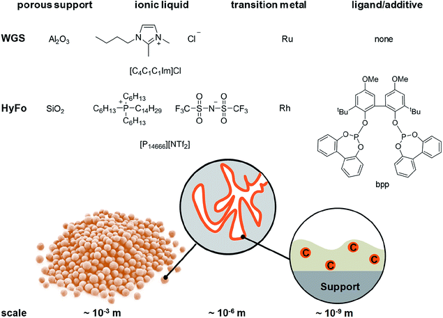
Homogeneous catalysts offer several advantages over their heterogeneous counterparts: especially mild reaction conditions, higher activity and better selectivity.1 In light of depleting fossil fuel reserves, the use of such catalysts is highly recommended.2 However, recycling of homogeneous catalysts from the product stream constitutes a significant drawback for technical implementation.3 To simplify the recycling of liquid catalysts, the supported ionic liquid phase (SILP) technology was developed.4 SILP technology is a fundamental, new approach to achieve the ambitious goal of effectively and permanently immobilizing homogeneous catalyst complexes for continuous processes.5 SILP technology involves surface modification of a porous solid by dispersing a thin film of non-volatile ionic liquid on the inner surface of the support material. Thus, the dissolved homogeneous catalyst does not evaporate into the gaseous reactant stream and is retained inside the fixed SILP catalyst bed. The concept has been developed within the past 15 years in academia and industry, including the successful proof-of-concept for ultra-low temperature water–gas shift reaction6 (in cooperation with Clariant and Linde) and gas-phase hydroformylation7 (in cooperation with Evonik) by some of the authors. Both reactions are of high industrial importance. The water–gas shift (WGS) reaction, meaning the exothermic conversion of carbon monoxide and water to carbon dioxide and hydrogen, still plays an essential role in the technical hydrogen production nowadays. Carbon monoxide, which is formed during hydrocarbon steam reforming and can act as severe catalyst poison, e.g., for ammonia synthesis or fuel cell (FC) catalysts, can be reduced to low levels below 0.5 vol%.8 Due to the exothermic nature of the WGS equilibrium reaction, low temperatures around 150 °C and below are desirable to achieve CO levels below 10 ppm.9 Commercial heterogeneous catalysts require reaction temperatures around 200 °C and yield a CO level of 0.3 vol%. Such concentrations are still too high for e.g. the Pt catalyst in FC systems or the Fe catalyst in the Haber–Bosch process.10,11 In 2010, a Ru-SILP catalyst was developed by Werner et al. that allows operation between 120 °C to 160 °C, thereby outperforming state of the art commercial catalysts.6,12 The SILP catalyst is made of a rutheniumchlorocarbonyl dimer dissolved in the ionic liquid 1-butyl-2,3-dimethylimidazolium chloride [C4C1C1Im]Cl inside porous γ-alumina (see Fig. 1). Further improvement of this promising catalyst system could be better heat management to avoid hot spots and in situ removal of one of the formed products (CO2 or H2) via membranes in order to simplify downstream separation.Promising SILP catalysts have also been developed that allow hydroformylation of highly diluted or mixed feeds with exceptionally high selectivity, adding value to industrial waste streams.13,14 For the first time, the applicability of sophisticated but labile phosphite ligands (see bpp in Fig. 1) in hydroformylation has been reported with catalyst stabilities exceeding 800 h time-on-stream with cumulative turn-over-numbers exceeding 400.000 and high space-time-yields of 850 kgproduct mSILP−1 h−1.13 These values are high enough to make new hydroformylation processes based on SILP materials economically viable. A possible drawback is the undesired aldol condensation, in which two aldehyde molecules can react to form side products with high boiling points that accumulate in the ionic liquid film.15,16 This side reaction has to be suppressed in order to maintain high catalyst activity. One option is to remove the formed aldehydes immediately from the SILP catalyst in a membrane type reactor. Therefore, we aim at developing SILP based membrane reactors for both WGS and hydroformylation reactions. While the WGS will benefit from product removal due to the shift in equilibrium conversion, the yield of the desired aldehyde in hydroformylation will benefit from in situ removal due to less aldol condensation (see Scheme 1).
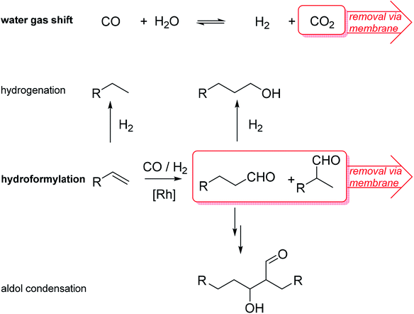 | ||
| Scheme 1 Reaction schemes of SILP catalyzed water–gas shift (WGS) and hydroformylation (HyFo) with attempted in situ removal of one product. R = alkyl chain. | ||
A material suitable for both membrane formation and SILP impregnation has to be identified. Recently, we have shown that polymer-based spherical activated carbon (PBSAC) can serve as support for SILP hydroformylation catalysts.17,18 Proper surface modification can yield SILP catalysts with TOF of 700 molpentanal molRh h−1 in gas-phase 1-butene hydroformylation.18 Using another carbonaceous material, in 2014 Gendel et al. demonstrated the fabrication of freestanding hollow fibers made only from multi-walled carbon nanotubes (MWCNT).19
In this work, the fabrication procedure is altered to include small-scale particles within the MWCNT network, which enhance catalytic activity in a SILP reaction system. The ability to tune microtubes via the addition of small particles was first reported by Keller et al.20 This particle inclusion offers possibilities to adjust porosity and pore volume for a proper catalyst distribution in the microtube. Previous experiments indicated that silica (SiO2) is the support material of choice for the hydroformylation reaction, while alumina (Al2O3) particles work well in the water gas shift reaction.12,21
Such small-scale particles are unable to act as a freestanding membrane support material on their own. However, integrated into a MWCNT network, the MWCNTs combined with small particles build a freestanding catalytic support, which is tunable to different reaction systems, depending on various catalysts and reaction kinetics. In order to evaluate the applicability of these microtubes as support for SILP catalyzed reactions, we analyzed the performance of short MWCNT tube fragments as a structured packing for both reactions mentioned above. We included these particles into the microtube structure with various particle ratios for a better understanding of the reaction performances.
Experimental
All gases were purchased from Linde Gas. For hydroformylation, 1-butene (99.5 vol%), CO (99.95 vol%) and H2 (99.9990 vol%) were used with He (99.9990 vol%) as balance. Catalytic WGS tests were conducted using a mixture of CO (99.95 vol%) and H2O diluted with N2 (99.9990 vol%).Multiwalled carbon nanotubes were purchased from Sigma-Aldrich. The MWCNT's have an outside diameter of 10 nm ± 1 nm, an inside diameter of 4.5 nm ± 0.5 nm and are 3–6 μm long. Their carbon content is ≥98%. Silica particles SYLOID® C 803 with an average diameter of 3.4–4 μm were provided from Grace. Two different alumina oxide particles were used in this study. Puralox TM 100/150 UF with an average diameter of 2.5 μm were kindly donated from Sasol Germany GmbH. Gamma-alumina (γ-Al2O3) powder with a particle size of approx. 5 μm was purchased from Pengda Munich GmbH. Polypropylene (PP) S6/2 hollow fiber membranes for filtration of MWCNT/MWCNT + particle suspension were ordered from Accurel (1.8 ± 0.15 mm inside diameter). Further chemicals used were Triton-X 100 (Carl Roth), iso-propanol (Applichem, 98% purity) and deionized water (2.2 μS cm−1).
Preparation of MWCNT, MWCNT-SiO2 and MWCNT-Al2O3 materials
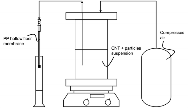
A detailed description of the production of MWCNT based microtubes and possibilities for geometric variations, e.g., wall thickness and length, can be found elsewhere.19 Within this work, a focus was placed on the production of MWCNT microtubes with integrated particles in the MWCNT wall structure. For the hydroformylation case study, 500 mg of various particle combinations of MWCNT and SiO2 were suspended in 500 mL deionized water. The tested fractions were 0, 30, 50, and 70 wt% SiO2 and are listed in Table S1.† For the case study of the WGS reaction, alumina oxide particles from either Sasol or Pengda were mixed with MWCNT and suspended in 500 mL deionized water. The combination of Al2O3 particles and MWCNT added up to 500 mg. The tested fractions were 0, 10, 30 and 50 wt% Al2O3 and are listed in Table S2.† Furthermore, all three materials, MWCNT, SiO2 and Al2O3 were tested in their powder form for reference values.The fabrication process of the freestanding tubes was the same for both SiO2 and Al2O3 particles integration. To ensure well-dispersed particles within the suspensions, 5 mL of Triton-X 100 was added as a surfactant. Each suspension was sonicated for three hours (Hielscher UP200S) and subsequently stirred with a magnetic stirrer for an hour. In consecutive steps, each suspension was filtered in an inside out filtration through the polypropylene (PP) S6/2 hollow fiber membrane, which had been cut to a length of 250 mm and glued shut on one end. Filtration occurred with a constant pressure of 5 bar until 3.4 mLsuspension cmPP-membrane−1 were transported through the membrane. A scheme of the experimental set-up is given in Fig. 2.
The MWCNT/particle suspension forms a filter cake on the inside of the PP membrane during filtration. After the filtration, a cleaning step was added, to remove any remaining Triton-X 100 impurities in the filter cake. 50 mL of isopropanol were flushed through the PP membrane with 0.7 mL min−1 using a syringe pump (Harvard Apparatus, PHD Ultra).
This cleaning step is necessary because otherwise, the MWCNT based microtubes exhibit defects.19 These defects destabilize the microtubes, which would hinder their use as a support material. After removing the surfactant, a drying step was performed overnight in a vacuum oven at 30 °C and 30 mbar. In a final step, one end of the PP membrane was carefully cut off with a scalpel to pull out the formed MWCNT microtube from the shell.
SILP material characterization
High-resolution images were taken using two different scanning electron microscopes (S-3000 and S-4800, Hitachi). The samples were sputtered with an approximately 3 nm thick gold layer in a high vacuum sputter coater (EM ACE600, Leica). For sample preparation, MWCNT microtubes were placed in liquid nitrogen for 2 minutes and broken immediately after exiting the liquid nitrogen bath. The Barrett, Joyner and Halenda (BJH) method was used to estimate pore size and pore volume from nitrogen adsorption isotherms.22 The nitrogen adsorption was conducted at −196 °C (ASAP 2020, Micromeritics). Prior to analysis, all samples were dried in a vacuum oven overnight at 30 mbar and 50 °C. Afterward, the samples were degassed at 250 °C for four hours at 20 μbar. Thermogravimetric analysis (TGA STA6000, PerkinElmer) was used to determine the thermal stability of MWCNT microtubes.Preparation of MWCNT-based SILP WGS catalysts
Water gas shift SILP catalyst were prepared using standard Schlenk techniques. In a first step, the ionic liquid 1-butyl-2,3-dimethylimidazolium chloride [C4C1C1Im]Cl was dissolved in dichloromethane (typically 30 mL DCM) in a round-bottom Schlenk flask under argon atmosphere. After stirring the solution till complete dissolution of the ionic liquid (10–15 min at 25 °C), the precursor complex [Ru(CO)3Cl2]2 (purchased from Alfa Aesar) was added, followed by another 15 min of stirring. Subsequently, 0.4 g of the MWCNT-Al2O3 support material (crushed to approx. 1 mm length) was added and stirred for an additional 5 min. The stirrer bar was taken out of the flask before the solvent was removed, to reduce any further crushing of the particles due to mechanical stress. The solvent withdrawal was carried out in two steps in a rotary evaporator (step 1: 2 h, 40 °C, 900 mbar; step 2: 1 h, 40 °C, <3 mbar). After solvent removal, free-flowing, shiny black SILP catalyst particles were obtained when using MWCNT supports, while pure alumina yielded a yellow SILP powder. The resulting catalyst had a nominal metal loading of wRu = 2 wt% (see eqn (1)). | (1) |
The pore filling degree with ionic liquid, defined as ratio between ionic liquid volume and total pore volume, was set to αIL = 34 vol% (see eqn (2)).
 | (2) |
Preparation of MWCNT-based SILP hydroformylation catalysts
Hydroformylation SILP catalysts were handled and prepared under inert conditions inside a glove box, using standard Schlenk techniques. For the impregnation of the MWCNT and MWCNT-SiO2 support material, the ionic liquid tetradecyltrihexylphosphonium bis(trifluoromethylsulfonyl)imide [P14666][NTf2] in dichloromethane was added to the support material and stirred for 10 min. Next, a mixture of the precursor Rh(acac)(CO)2 and the biphephos ligand bpp dissolved in DCM was added and stirred for additional 20 min. The solvent was then slowly removed under reduced pressure (step 1: 2 h, 40 °C, 900 mbar; step 2: 1 h, 40 °C, <3 mbar) to facilitate the homogeneous coating of the support material, resulting in the average, adjusted degree of pore filling. The resulting SILP materials contained a rhodium loading of wRh = 0.2 wt%, a ligand/Rh ratio of 4 and an ionic liquid loading of αIL = 10 vol%.Catalytic tests in WGS
A continuously operated tubular reactor was used that has been reported previously.23 The flow scheme of the test rig is given in the ESI (Fig. S4†). For a typical experiment, 0.4 g of the prepared SILP catalyst was placed in the tubular reactor on a glass wool covered frit to keep the fixed bed in place. Following a pressure test, the reactor was heated to the reference temperature of 120 °C under a nitrogen atmosphere. Once the temperature was reached, the rig was switched into bypass mode, and the streams of CO, N2 and H2O were adjusted with a partial pressure ratio of pN2![[thin space (1/6-em)]](https://www.rsc.org/images/entities/char_2009.gif) :
:![[thin space (1/6-em)]](https://www.rsc.org/images/entities/char_2009.gif) pCO
pCO![[thin space (1/6-em)]](https://www.rsc.org/images/entities/char_2009.gif) :
:![[thin space (1/6-em)]](https://www.rsc.org/images/entities/char_2009.gif) pH2O = 7
pH2O = 7![[thin space (1/6-em)]](https://www.rsc.org/images/entities/char_2009.gif) :
:![[thin space (1/6-em)]](https://www.rsc.org/images/entities/char_2009.gif) 1
1![[thin space (1/6-em)]](https://www.rsc.org/images/entities/char_2009.gif) :
:![[thin space (1/6-em)]](https://www.rsc.org/images/entities/char_2009.gif) 2 and a total pressure of ptot = 1 bar. When the IR-Analyzer (X-STREAM Enhanced XEGP, Emerson) showed stable values, the data logger was started to take reference values for 15 minutes (one data point per 30 seconds) before switching into reactor mode. The temperature of the tubular reactor was varied at constant volume flows between 120 °C and 140 °C in steps of 5 °C. Every set point is kept for 5 hours in which steady-state conditions were reached.
2 and a total pressure of ptot = 1 bar. When the IR-Analyzer (X-STREAM Enhanced XEGP, Emerson) showed stable values, the data logger was started to take reference values for 15 minutes (one data point per 30 seconds) before switching into reactor mode. The temperature of the tubular reactor was varied at constant volume flows between 120 °C and 140 °C in steps of 5 °C. Every set point is kept for 5 hours in which steady-state conditions were reached.
Catalytic tests in hydroformylation
The continuous gas-phase hydroformylation experiments were conducted at 100 °C and 11 bar pressure using a fixed bed reactor set-up (for details see Fig. S5†).24 The syngas flows (33H2 mLN min−1, 33 CO mLN min−1) were regulated by a mass flow controller (Bronkhorst). 1-Butene (0.067 mL min−1) was dosed by a minipump (Smartline Pump 100 by Knauer) equipped with a 10 mL pump head. An additional inert gas flow of helium was applied by a mass flow controller (Bronkhorst) during the start of the reaction (decreased in steps of 25 mLN min−1 from 100 to 0 mLN min−1). The gaseous substrate stream was contacted with the SILP catalyst fixed bed (0.124 g SILP + 0.9 g inert Silica 60, 63–200 μm) in a tubular reactor with a residence time of 7 seconds. An on-line gas chromatograph (Bruker 450 GC) monitored the product feed stream with two FID detectors (CP-Wax 52CB, 25 m length, 0.53 mm inner diameter, 2 μm coating for C5–C10 separation; CP-Porabond Q, 25 m length, 0.53 mm inner diameter for C4 separation) and one TCD detector (permanent gases).The SILP hydroformylation activity is expressed by means of the turnover frequency TOF (in h−1) which is calculated according to eqn (3).
 | (3) |
For SILP WGS the molar flow of product cannot be determined in high accuracy due to a change of the total flow caused by the condensation of water before the dry gas flows through the online IR-analyzer. Here, the TOF has to be modified according to eqn (4).
 | (4) |
The molar flow of substrate is known from the calibrated MFC and the degree of conversion is calculated based on the CO signal from the gas analyzer.
Results and discussion
First, we present the results from the MWCNT microtube fabrication and analysis, as well as the preparation of composite MWCNT-SiO2 and MWCNT-Al2O3 materials. These materials were tested in WGS and hydroformylation, which constitutes the second part of this chapter.MWCNT microtube fabrication
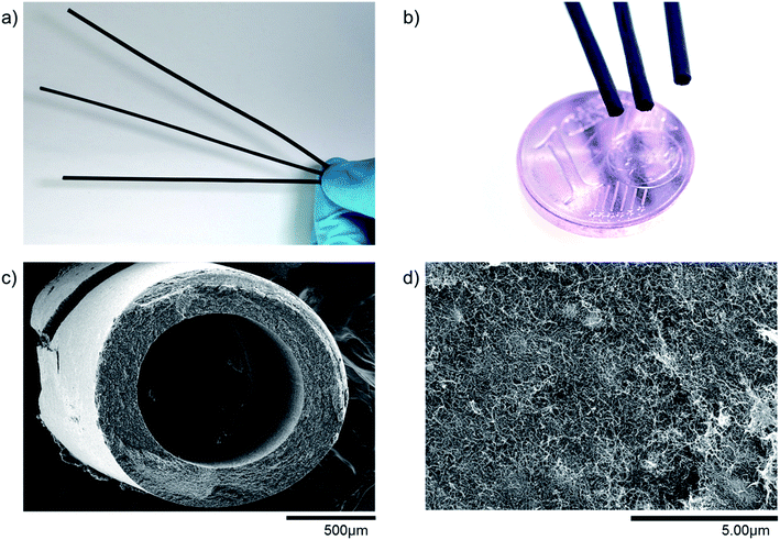
Producing freestanding MWCNT based microtubes is possible with the production procedure developed by Gendel et al.19 As can be seen in Fig. 3(a–c), the microtubes produced in this work are self-supporting, long and thin hollow fibers. Measurements show that all fibers are above 200 mm in length and have an outside diameter of around 1.7 mm. The outside diameter of the microtube is slightly smaller than the inside diameter of the PP filtration membrane because the microtube shrinks during the drying step.Field emission scanning electron microscopy (FESEM) allows to evaluate the particle distribution within the microtube wall. The thickness of the microtube wall depends on the filtration time and filtration flux, being in the range of 150–350 microns. Fig. 3d shows the catalyst-free microtube surface structure of pure MWCNTs. Even though there are no particles embedded into the network of MWCNTs, it seems as if some small clusters form beneath the surface. These clusters consist of agglomerated MWCNTs, and they can form dense structures, which also affect the homogeneity in porosity of the MWCNT network as explained in the next section. The number of clusters depends much on the preparation and the corresponding homogeneity of the solution to be filtered.
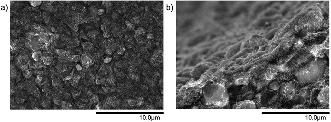
In comparison to the pure MWCNT microtube from Fig. 3(d), the integration of small particles considerably changes the structure of the microtube. Fig. 4 is an example of a surface and a cross-section view of a 50 wt% MWCNT/50 wt% SiO2 microtube. The small SiO2 particles are evenly distributed within the MWCNT network. The same effect is observed for Al2O3 particles as well, as can be seen in Fig. S1.†
Particle loading has a strong influence on microtube stability. Mechanically stable, freestanding MWCNT-SiO2 microtubes can be formed up to a particle loading of 70 wt% of SiO2 particles. For MWCNT-Al2O3 microtubes, it was not possible to increase the particle loading above 50 wt% without breaking the fibers during production. For particle loadings larger than 70 wt% in SiO2 rich microtubes or 50 wt% in Al2O3 rich microtubes, the structures became unstable and some samples broke upon removing them from the PP filtrations membranes. Therefore, all results presented in the following were obtained with microtube particle loadings between 0–70 wt% in case of SiO2 rich microtubes and 0–50 wt% for Al2O3 rich microtubes.
The observations regarding MWCNT-microtube stability match well with the work from Keller et al., who discovered that bending strength of MWCNT microtubes reduced significantly with an increase in particle loading.20 A possible improvement of the MWCNT interconnection, and thus, the stability of the microtube can be achieved through crosslinking of amine-functionalized MWCNT's.25 The crosslinking increased the mechanical stability of buckypaper by more than two-fold, according to Zhang et al.,26 and could be tested in follow up work for MWCNT microtubes.
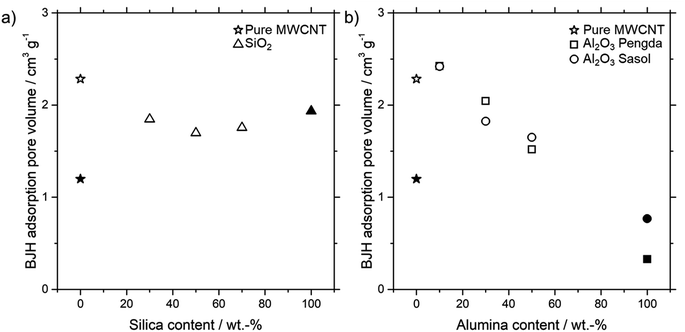
For the SILP impregnation into the porous microtubes, it is necessary to know the pore volume. As mentioned in the catalyst preparation section, it is sufficient to fill only a certain amount of pore volume with SILP solution. Fig. 5 shows the Barrett, Joyner and Halenda (BJH) adsorption pore volumes of different amounts of all three kinds of particles integrated into MWCNT microtubes, as well as the powder forms.
For the SiO2 particles, the pore volume decreases from a pure MWCNT microtube towards a 50% MWCNT-SiO2 combination. A further increase of SiO2 particles increases the pore volume again, towards the SiO2 powder pore volume. A possible explanation for this behavior is the entanglement of MWCNTs with SiO2 particles and, resulting from this interaction, the forming of new pores. Contrary to the MWCNT-SiO2 combination, the pore volume increases slightly for both MWCNT-Al2O3 combinations at 10 wt% Al2O3, before dropping continuously with higher particle loadings. Again, the entanglement of MWCNT's and particles seems to be a possible reason, which leads to the forming of new pores. A more detailed explanation can be found in the ESI including Fig. S2† of the differential analysis of pore volume depending on particle loading.
Continuous WGS catalysis
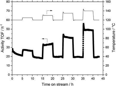
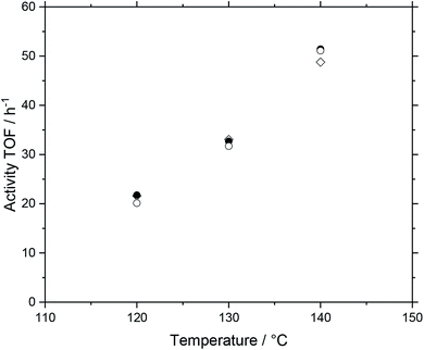
The basis for the evaluation of the MWCNT-Al2O3 composite materials in WGS SILP was a temperature variation at constant feed flows and compositions. A typical plot of results can be seen in Fig. 6, which summarizes the obtained catalytic values for a SILP catalyst based on pure alumina (Pengda) support material.After every temperature variation, the temperature was reset to the reference state of 120 °C, to investigate whether the system undergoes deactivation phenomena. The results show that the catalyst promotes stable values at all temperature stages after a start-up period in the first 120 °C-stage. For the sake of clarity and better comparability, every temperature variation experiment is turned into a turnover frequency (TOF) over temperature plot by averaging the measured data of a stable operation regime over a time of 30 minutes within every temperature stage. By doing so, Fig. 7 is obtained, which shows the same experimental run (Pengda, 5 μm particles) as a TOF-temperature plot. In addition, results from powdered Sasol support (Puralox TM 100/150 UF, 2.5 μm particles) and granulated alumina (Puralox NWa 155, 200–500 μm particles) are shown. From these data it becomes evident that the three systems had a similar activity at each reaction temperature.
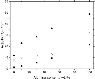
Next, we investigated the performance of MWCNT-alumina composite support materials. Different support materials made from varying fractions of MWCNTs and alumina-types (purchased from Pengda and Sasol) were examined. After preparation, the MWCNT material was reduced in length into fragments of approx. 1 mm length each, which were placed into the reactor. The prepared systems had alumina contents of 0 (pure MWCNT), 10, 30, 50 and 100 wt%. In Fig. 8 the results for the composite material based on alumina Pengda are shown; the behavior for Puralox TM 100/150 UF can be found in the ESI (Fig. S6†), which is almost identical. All systems showed a higher activity with higher temperatures following Arrhenius law without undergoing any deactivation over time. This temperature dependency leads to the conclusion that the support materials themselves are stable at elevated temperatures under reaction conditions. While all systems showed a similar increase in activity with rising temperature, the system with 50 wt% alumina deactivated to a minor degree from 120 to 130 °C.
Furthermore, a higher alumina content in the prepared support materials for the catalysts had a positive influence on activity. The higher the alumina content, the higher the activity of the investigated SILP catalyst system. We observe this trend throughout all three plotted temperature stages. The trend can be considered as quasi-linear, which is most prominent at 120 °C. All discussed trends can be observed in the catalyst systems using alumina from Sasol as well (see Fig. S6†).
While the WGS catalytic activity did not benefit from incorporating alumina particles in MWCNTs, the tubular geometries that might be accessible by these new composite materials (e.g., hollow fibers, tube bundles) can compensate for the effect of lower activity. On the way to a membrane reactor that would consist of several hundreds of MWCNT hollow fibers, the lower activity would be compensated by the more effective handling of SILP catalysts in combination with separation.
Continuous hydroformylation
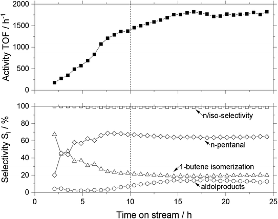
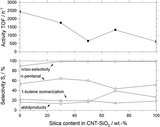
In a similar manner as for WGS, we tested the MWCNT-SiO2 composite supports for gas-phase hydroformylation of 1-butene in a continuous reactor setup. Fig. 9 shows the activity and selectivity over time on stream for a composite support containing 70 wt% MWCNT and 30 wt% SiO2. For a smoother start-up, especially to avoid high aldol formation, the reaction mixture was diluted with helium. The helium flow was reduced every 80 minutes from 100 to 0 mLN min−1 in four steps. Next to the TOF as a critical characteristic for catalytic activity, the selectivities for the primary and side products are shown as well as the n/iso-selectivity within the aldehyde fraction. This selectivity represents the amount of the desired n-pentanal in comparison to all pentanals formed. Side reactions are the hydrogenation to butane, the isomerization to cis-2-butene and trans-2-butene (combined as isomerization selectivity) as well as the subsequent reaction of n-pentanal to 3-hydroxy-2-propylheptanal which can undergo a condensation reaction to form 2-propylhept-2-enal (combined as aldol selectivity).The SILP catalyst required a long induction period of more than 13 h to reach a stable performance (the first two hours were bypass measurements). The purely silica based SILP catalyst also reached steady-state performance only after 15 h (see Fig. S7†). Interestingly, even after the reactor temperature had stabilized, which took approximately 10 hours, the system was not stable, and the activity kept increasing. After 15 hours, the MWCNT-SiO2 based SILP catalyst reached a steady state of approximately 1800 h−1 activity, corresponding to 4.8% conversion. The n-pentanal selectivity was very high at 99.2%, the total selectivity toward aldehydes stabilized at 64.2% and the isomerization tendency was around 19.4%. Aldol formation as the most problematic side reaction in gas-phase hydroformylation was low during the induction period but increased to a stable plateau of 13.5%. Such behavior hints at an ongoing process of restructuring of the ionic liquid film due to changes in the wettability when substrates and products dissolve.16 Especially the change in aldol content in the effluent stream of the reactor is a strong indication for the restructuring process. To compare different MWCNT-SiO2 compositions, we calculated the average values of the steady state for all selectivities, as well as the turnover frequency (see Fig. 10). Since the sample consisting of pure MWCNT material showed a steady deactivation throughout the observed period (see Fig. S8†), the initial TOF values were considered.
When comparing the MWCNT-SiO2 composite materials with pure MWCNT and SiO2, it becomes obvious that the SiO2 lowers the overall activity compared to pure MWCNT. The pure silica-based SILP catalyst had a TOF of 625 h−1, while the pure MWCNT based SILP was 400% more active around 2440 h−1. The activity of composite materials having different ratios between MWCNT and SiO2 gradually declined with increasing SiO2 content. The selectivity pattern did not reveal a clear trend, with all MWCNT-SiO2 based catalysts yielding n/iso-selectivity (96 ± 4%), moderate toward n-pentanal (55 ± 7%), and isomerization (19 ± 2%). The aldol content varied significantly between the different catalysts, being 22 ± 9% on average. Especially higher amounts of silica content show an increased aldol and therefore decreased n-pentanal formation. We explain this trend with the higher amount of silanol groups on the surface, which enhance the acid/base-catalyzed aldol formation. Calcining the silica at an elevated temperature of 600 °C for several hours reduces the number of surface silanol groups significantly.5a Due to a combustion temperature in the range of 400–500 °C of the MWCNT microtubes, calcining at 600 °C was not possible. The combustion temperature of MWCNT microtubes in air was analyzed with TGA measurements (see Fig. S3†).
Conclusion
Improving large-scale chemical reactions to reduce emissions and costs is a significant challenge of today's society. On the one hand, catalyst immobilization via SILP technology offers an opportunity to combine the advantages of homogeneous and heterogeneous catalytic reactions. On the other hand, tunable MWCNT based microtubes can serve as freestanding support materials for catalytic reactions and structure the inside of a reactor. This can lead to avoiding high pressure drops or packing problems, as they occur, e.g., in packed bed reactors as well as to better control of mass and heat transport inside the reactor. In this work, the SILP platform was integrated into a new tubular geometry based on MWCNT. The ability to tune microtubes with porous particles, which are known for their good SILP applicability, is advantageous for incorporating the SILP system into structured supports and reactors.The experiments showed that the reaction performance in the WGS reaction is lower for Al2O3 particle integrated microtubes compared to pure Al2O3 powder. Nonetheless, the combined support shows stable and selective behavior. The catalytic activity of MWCNT microtubes for the hydroformylation reaction is very high for pure MWCNT microtubes and decreases for higher SiO2 contents. However, the catalytic stability is low if the materials are not adequately calcined, which is difficult, because of thermal instability of MWCNTs above 600 °C.
WGS and hydroformylation of 1-butene are two promising case studies, which are part of the ROMEO project, targeting the development of SILP membrane reactor systems.27 The technology to combine SILP and tunable MWCNT based microtubes could be expanded and used for other chemical reactions. Hydroformylation of smaller olefins (e.g. propene) is feasible, while for higher olefins (e.g. hexenes or octenes) the pore condensation inside the monolithic structure can hamper the overall efficiency. Next, we aim to apply molecular selective membranes on the microtube surface: a self-supporting reaction system combined with a membrane to separate products in situ would be a significant step towards process intensification.
Conflicts of interest
There are no conflicts to declare.Acknowledgements
The authors gratefully acknowledge financial support from the European Commission within the Horizon2020-SPIRE project ROMEO (grant agreement number 680395). Furthermore, the authors want to thank Heike Zander, for her support in the MWCNT-microtube production.References
- Applied Homogeneous Catalysis with Organometallic Compounds, ed. B. Cornils, W. A. Herrmann, M. Beller and R. Pacielo, Wiley-VCH, Weinheim, 2017 Search PubMed.
- 12 Design Principles of Green Chemistry, ACS Green Chemistry Institute, http://www.acs.org/greenchemistry, accessed May 2019 Search PubMed.
- Multiphase Homogeneous Catalysis, ed. B. Cornils, W. A. Herrmann, I. T. Horváth, W. Leitner, S. Mecking, H. Olivier-Bourbigou and D. Vogt, Wiley-VCH, Weinheim, 2005 Search PubMed.
- Supported Ionic Liquids – Fundamentals and Applications, ed. R. Fehrmann, A. Riisager and M. Haumann, Wiley-VCH, Weinheim, 2014 Search PubMed.
- (a) A. Riisager, R. Fehrmann, S. Flicker, R. van Hal, M. Haumann and P. Wasserscheid, Angew. Chem., Int. Ed., 2005, 44, 815 CrossRef CAS PubMed; (b) A. Riisager, R. Fehrmann, M. Haumann and P. Wasserscheid, Eur. J. Inorg. Chem., 2006, 695 CrossRef CAS; (c) A. Riisager, R. Fehrmann, M. Haumann and P. Wasserscheid, Top. Catal., 2006, 40, 91 CrossRef CAS.
- S. Werner, N. Szesni, R. W. Fischer, M. Haumann and P. Wasserscheid, Phys. Chem. Chem. Phys., 2009, 11, 10817 RSC.
- J. Marinkovic, A. Riisager, R. Franke and M. Haumann, Ind. Eng. Chem. Res., 2019, 58, 2409 CrossRef CAS.
- G. Jacobs and B. H. Davis, Catalysis, 2007, 20, 122 CAS.
- R. M. Laine and E. J. Crawford, J. Mol. Catal., 1988, 44, 357 CrossRef CAS.
- X. Cheng, Z. Shi, N. Glass, L. Zhang, J. Zhang, D. Song, Z.-S. Liu, H. Wang and J. Shen, J. Power Sources, 2007, 165, 739 CrossRef CAS.
- M. Appl, Ammonia, 3. Production Processes, in Ullmann's Encyclopedia of Industrial Chemistry, Wiley-VCH, Weinheim, 2012 Search PubMed.
- S. Werner, N. Szesni, M. Kaiser, R. W. Fischer, M. Haumann and P. Wasserscheid, ChemCatChem, 2010, 2, 1399 CrossRef CAS.
- M. Jakuttis, A. Schönweiz, R. Franke, K.-D. Wiese, M. Haumann and P. Wasserscheid, Angew. Chem., Int. Ed., 2011, 50, 4492 CrossRef CAS.
- M. Haumann, M. Jakuttis, R. Franke, A. Schönweiz and P. Wasserscheid, ChemCatChem, 2011, 3, 1822 CrossRef CAS.
- A. Riisager, R. Fehrmann, M. Haumann, B. S. K. Gorle and P. Wasserscheid, Ind. Eng. Chem. Res., 2005, 44, 9853 CrossRef CAS.
- (a) A. Schönweiz, J. Debuschewitz, S. Walter, R. Wölfel, H. Hahn, K. M. Dyballa, R. Franke, M. Haumann and P. Wasserscheid, ChemCatChem, 2013, 5, 2955 CrossRef; (b) A. Kaftan, A. Schönweiz, I. Nikiforidis, W. Hieringer, K. M. Dyballa, R. Franke, A. Görling, J. Libuda, P. Wasserscheid, M. Laurin and M. Haumann, J. Catal., 2015, 321, 32 CrossRef CAS.
- A. Weiß, M. Munoz, A. Haas, F. Rietzler, H.-P. Steinrück, M. Haumann, P. Wasserscheid and B. J. M. Etzold, ACS Catal., 2016, 6, 2280 CrossRef.
- A. Weiß, M. Giese, M. Lijewski, R. Franke, P. Wasserscheid and M. Haumann, Catal. Sci. Technol., 2017, 7, 5562 RSC.
- Y. Gendel, O. David and M. Wessling, Carbon, 2014, 68, 818 CrossRef CAS.
- L. Keller, B. Ohs, L. Abduly and M. Wessling, Chem. Eng. J., 2019, 359, 476 CrossRef CAS.
- M. Jakuttis, Dissertation, Friedrich-Alexander-Universität Erlangen-Nürnberg, 2013.
- E. Barrett, L. Joyner and P. Halenda, J. Am. Chem. Soc., 1951, 73, 373 CrossRef CAS.
- S. Werner, Dissertation, Friedrich-Alexander-Universität Erlangen-Nürnberg, 2011.
- A. Schönweiz, Dissertation, Friedrich-Alexander-Universität Erlangen-Nürnberg, 2014.
- O. Zabihi, M. Ahmadi, M. Bagherjeri and M. Naebe, RSC Adv., 2015, 98693 Search PubMed.
- J. Zhang, D. Jiang, H. Peng and F. Qin, Carbon, 2013, 63, 125 CrossRef CAS.
- http://www.romeo-h2020.eu/, accessed June 2019.
Footnotes |
| † Electronic supplementary information (ESI) available. See DOI: 10.1039/c9ra04830h |
| ‡ Both authors contributed equally to the paper. |
| This journal is © The Royal Society of Chemistry 2019 |

