 Open Access Article
Degradation of methylene blue by dielectric barrier discharge plasma coupled with activated carbon supported on polyurethane foam
Lihang Wu,
Qinglong Xie,
Yongbo Lv,
Zhiyong Zhang,
Zhenyu Wu,
Xiaojiang Liang,
Meizhen Lu and
Yong Nie
 *
*
China Petroleum and Chemical Industry Federation Engineering Laboratory of Biodiesel Technology, Zhejiang Provincial Key Laboratory of Biofuel, College of Chemical Engineering, Zhejiang University of Technology, Hangzhou, Zhejiang 310014, China. E-mail: ny_zjut@zjut.edu.cn; 201101390720@zjut.edu.cn; xieql@zjut.edu.cn; 1437156976@qq.com; 799989893@qq.com; wuzhenyu@zjut.edu.cn; 291913062@qq.com; luzhen@zjut.edu.cn; Fax: +86 571-88320053; Tel: +86 57-88320646
First published on 20th August 2019
Abstract
The degradation of methylene blue (MB) using a novel dielectric barrier discharge plasma reactor coupled with activated carbon supported polyurethane foam (AC/PUF) was investigated in this paper. The plasma reactor combining a glass bead-packed bed and a microporous plate was developed. The AC/PUF provided sufficient contact area between carbon media and pollutants and hence revealed a good MB removal capacity. The effects of input voltage and initial MB solution concentration on MB degradation efficiency were examined. Kinetic study indicated that plasma and AC/PUF in the coupled system had a good synergistic effect in MB degradation. The degradation efficiency of 100 ppm MB solution could reach 97.9% with 10 min treatment in the coupled system, which was close to that obtained by plasma treatment alone for 30 min (97.5%). The COD removal in the plasma and AC/PUF coupled system (90.7%) was much higher than that obtained by plasma treatment followed by AC/PUF adsorption (58.3%). In addition, the energy yield (G50) of the coupled system was up to 38.3 g kW−1 h−1, suggesting great energy efficiency of the system. Moreover, repeated use experiments of AC/PUF showed the good utilization potential of the coupled system. Finally, a possible degradation pathway of MB was proposed.
1. Introduction
Nowadays, wastewater produced in various industrial activities has become a worldwide problem due to its severe environmental pollution and human health risks. The textile dyeing industry is one of the major contributors to wastewater pollution due to massive discharge of high concentrations of dyes. It is estimated that over 7 × 10⁵ tons of dyes are produced annually.1 Most organic substances in dyeing wastewaters are hazardous and toxic. Moreover, dye molecules have complex and stable structures due to the existence of auxochromes (water soluble bonding compound) and chromophores (color giving compound).2 Thus, the pollutants in dyeing wastewaters are difficult to degrade by traditional physical, chemical and biological treatment methods.3 Effective approaches for the removal of dyes have attracted much research interest.Recently, considerable attention has been paid to in situ hydroxyl radicals-based methods, namely advanced oxidation processes (AOPs).4 The standard oxidation potential of hydroxyl radicals is as high as 2.8 V, only next to fluorine (E0: 3.06 V). Numerous hazardous compounds can be non-selectively oxidized and decomposed to CO2, H2O and inorganic ions by hydroxyl radicals usually at room temperature and normal pressure.5 Photocatalysis,6 ozone,7 Fenton process8 and non-thermal plasma (NTP) technology9 are typical examples of AOPs. Among these methods, NTP can simultaneously generate various physical and chemical effects, including UV light, shockwave, electric field, and reactive species such as ˙OH, ˙O, O3 and H2O2.10 Thus, the application of NTP for elimination of organic compounds, especially those with high toxicity and low biodegradability in wastewater, has been widely studied.11
Among NTP processes, dielectric barrier discharge (DBD) plasma has advantages of simple reactor structure and steady discharge state, which has been widely used in dyeing wastewater treatment.12–14 Reddy et al.15 adopted a DBD reactor to investigate the degradation and mineralization of methylene blue (MB) solution. With the addition of Fe2+, highest MB degradation (over 95%) and TOC removal (21%) were obtained after 25 min treatment at 100 mg L−1 MB concentration. Degradation of MB solution by different AOPs was compared by Aziz et al.16 The maximum MB mineralization of 88% was obtained using the DBD plasma under the argon atmosphere and in the presence of homogeneous Fe2+ catalyst which was due to the occurrence of an additional Fenton reaction. Iervolino et al.17 studied the removal efficiency of MB by DBD reactor using oxygen as process gas. Complete degradation and mineralization of methylene blue was achieved after only 5 min of treatment time. Degradation of various textile dyeing wastewater under DBD plasma treatment was studied by Tichonovas et al.3 and high degradation efficiency was obtained for a wide variety (13 overall) of dyes. It suggested the promising applicability of DBD reactor in dyeing wastewater treatment. However, the sole plasma discharge treatment is widely considered economically-expensive since insufficient utilization of plasma active species would result in demand of significant amounts of electrical energy. In addition, mineralization is not achieved in many cases, which causes secondary problems with partially oxygenated products.15 Thus, it is urgent to develop more energy-efficient plasma reactor or combine the plasma reactor with other treatment methods to further improve the degradation and mineralization efficiency.
Carbon materials have been widely used in treating wastewater as adsorbents due to their excellent adsorption properties.18 On the other hand, carbon materials give rise to the possibility of catalytic oxidation reactions on the carbon surface which in turn enhances the degradation efficiency of pollutants.19 The combination of activated carbon20,21 or activated carbon fibers22,23 with plasma treatment showed enhanced performance of pollutants degradation and COD removal compared with plasma treatment alone. The integrated treatment process may synergize the advantages of their treatment performances, while overcoming their respective limitations.19 However, activated carbon can hardly distribute evenly in plasma reactor, especially in gas–liquid reactor, which causes inadequate contact between pollutants and carbon media and hence lower removal efficiency. In addition, the complicated fabrication process and high cost of activated carbon fibers limit their industrial application. Therefore, it is necessary to find some low-cost materials for activated carbon immobilization to improve its contact with the pollutants.
Polyurethane foams alone or combined with carbon media have been recently used for wastewater treatment by adsorption.24 Lefebvre et al.25 used activated carbon media immobilized on polyurethane foams (AC/PUF) for dye adsorption. The developed material provided sufficient contact between carbon media and pollutants and hence exhibited a good adsorption capacity. In addition, the material had advantages of large specific surface, high porosity, small pressure drop, good transport properties and low cost. However, no studies on AC/PUF coupled with DBD plasma reactor for dyeing wastewater treatment were reported.
In this work, a novel DBD plasma reactor combining glass beads packed bed and microporous plate was developed. The commercial AC/PUF was coupled with the novel plasma reactor for the treatment of dyeing wastewater. MB was selected as the model compound due to its stable molecular structure and wide usage. The AC/PUF material was characterized by scanning electron microscopy (SEM). The effects of input voltage and initial concentration of MB solution on MB degradation by DBD plasma with and without AC/PUF were examined. The MB degradation kinetics and the synergistic effect of DBD plasma and AC/PUF were investigated. In addition, the experiment for repeated use of AC/PUF was conducted to explore its application potential. Furthermore, the degradation byproducts were analyzed by liquid chromatography-mass spectrometry (LC-MS) and a possible degradation pathway for MB was proposed.
2. Materials and methods
2.1 Materials
Methylene blue (MB) was bought from Shanghai Titan Scientific Co., Ltd, Methanol for HPLC was purchased from Tianjin Siyou Scientific Co., Ltd. Reagents for chemical oxygen demand (COD) measurement were provided by Lianhua technology Co., Ltd. AC/PUF was purchased from Suzhou Tanxuanfeng Activated carbon Co., Ltd. Deionized water was used for solution preparation. Unless otherwise stated, all of the chemicals are analytical reagent grade.2.2 Experimental setup and methods
Fig. 1 shows the novel DBD plasma reactor comprising glass tank (inner diameter: 60 mm; height: 100 mm), porous diffuser plate (average pore size: 15–30 μm; diameter: 45 mm; thickness: 5 mm) and stainless steel plates (diameter: 30 mm; height: 3 mm) as ground and high voltage electrodes. The DBD reactor was energized by high voltage generated by a high frequency power supply (CTP-2000K, Nanjing Suman Electronics Co., Ltd.). The high voltage electrode was placed below the microporous diffuser plate and surrounded by glass beads. The ground electrode was immersed in liquid. The distance from high voltage electrode to porous diffuser plate was 4 mm. The indoor air was fed to the DBD reactor from the bottom by an air pump. Discharge was initially generated in beads packed bed region and can spread into microporous plate with higher air flow rate. Thus, microdischarges were generated in micropores on the porous diffuser plate and in the gas film formed on the interface of plate and solution. The active plasma species including ozone formed in beads packed bed region and radical species generated in situ by microdischarges can directly react with contaminants in wastewater.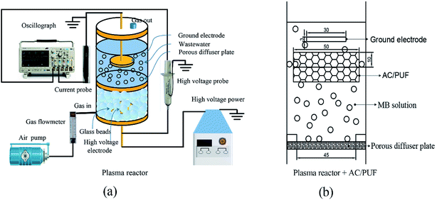 | ||
| Fig. 1 (a) Diagram of the experimental apparatus; (b) 2D front view of the sole reactor with AC/PUF. | ||
Batch experiments were conducted to explore the influences of different factors on the efficiency of MB degradation using plasma reactor with and without AC/PUF. Firstly, various input voltage (6 kV, 7 kV, 8 kV) was adopted to investigate its effect on MB degradation efficiency. In addition, the effect of initial MB solution concentration (50, 75, 100, 150, 200 ppm) was explored. For each batch experiment, the total volume of the system was 100 mL. The air flow rate of 1.5 L min−1 was chosen according to preliminary experiments. AC/PUF was sheared into round shape with 50 mm in diameter and 10 mm in height. Before use, it was cleaned by deionized water for eliminating impurities and dried at 323 K for 2 h. The AC/PUF was put under ground voltage electrode and suspended in aqueous solution. Air was introduced into solution through porous plate and the formed bubbles rose up to AC/PUF, which can significantly increase the contact area of pollutants with AC/PUF. All the experiments were carried out at atmospheric pressure and ambient temperature. Each experiment was repeated at least three times.
2.3 Analysis methods
Surface morphology of AC/PUF samples was observed by SEM (TESCAN VEGA3) with an accelerating voltage of 10 kV. The functional groups on the surface of activated carbon were determined on a Bruker Tensor II Fourier transform infrared spectroscopy (FT-IR), with a resolution of 4 cm−1 and scanning time of 64. The elemental composition of AC/PUF was analyzed using an Elementar vario macro (Germany).Samples were taken during specific intervals. The concentration of MB solution was quantitatively analyzed using Agilent Cary 60 UV-Visible spectrophotometer at the wavelength of 664 nm. For high concentration, the sample was diluted first for accurate measurement. The MB degradation efficiency η can be described as:
 | (1) |
 | (2) |
A current probe (TCP-0030A, Tektronix) was used to measure the current (I) applied to the DBD reactor, with the signal detected and shown in a digital oscilloscope (DPO 3052, Tektronix). A 1000![[thin space (1/6-em)]](https://www.rsc.org/images/entities/char_2009.gif) :
:![[thin space (1/6-em)]](https://www.rsc.org/images/entities/char_2009.gif) 1 high voltage probe (P6015A, Tektronix) was used to measure the voltage (U) applied to the DBD reactor, with the signal detected and shown in a digital oscilloscope (DPO 3052, Tektronix).26 The discharge power for the packed-bed DBD reactor was calculated using:
1 high voltage probe (P6015A, Tektronix) was used to measure the voltage (U) applied to the DBD reactor, with the signal detected and shown in a digital oscilloscope (DPO 3052, Tektronix).26 The discharge power for the packed-bed DBD reactor was calculated using:
 | (3) |
The energy yield for MB degradation can be calculated by the following equation:
 | (4) |
The degradation products after 10 min treatment with and without AC/PUF were characterized using liquid chromatography-mass spectrometry (LC-MS) (Waters 2695-ThermoFisher LCQTM Deca XP plus) in the positive ion mode. The product samples were injected into the ESI source at a flow rate of 0.5 mL min−1. The mixture of methanol and ultrapure (9![[thin space (1/6-em)]](https://www.rsc.org/images/entities/char_2009.gif) :
:![[thin space (1/6-em)]](https://www.rsc.org/images/entities/char_2009.gif) 1) was used as mobile phase.
1) was used as mobile phase.
3. Results and discussion
3.1 Characterization of the AC/PUF sample
Fig. 2 showed the image of the commercial AC/PUF material and SEM images of AC/PUF before and after treating MB wastewater. Fig. 2b revealed that initial AC/PUF had relatively rough surface with abundant pores, which was utilized to adsorb the organic compounds and support active sites for pollutants degradation. It was obvious that there were no substances attached at first. However, some particles (seen in Fig. 2c) were distributed on the surface of AC/PUF and in the pores of AC/PUF after adsorption, indicating MB molecules were adsorbed. In addition, the morphology and structure of AC/PUF had no change after their use, suggesting the stability of the AC/PUF material.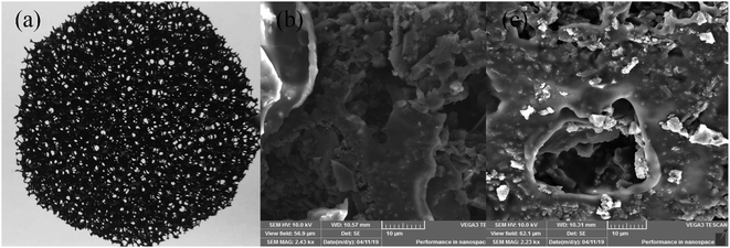 | ||
| Fig. 2 Commercially AC/PUF (a) and surface morphology of (b) original AC/PUF; (c) AC/PUF after adsorption. | ||
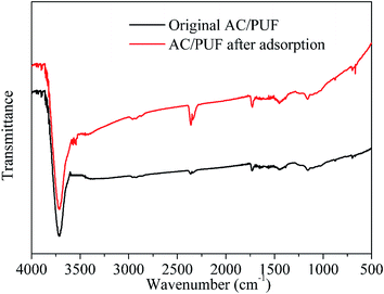
FTIR spectra of orginal AC/PUF and AC/PUF after adsorption are shown in Fig. 3. No obvious difference in peaks between both curves was observed, suggesting no change in functional groups on the carbon surface after use, which further indicated the stability of the AC/PUF material.
The results of elemental composition of AC/PUF were shown in Table 1. The contents of N and S in AC/PUF were slightly increased, which can be attributed to the adsorption of MB molecules and MB intermediates.
| C% | H% | N% | S% | |
|---|---|---|---|---|
| AC/PUF before adsorption | 78.22 | 3.902 | 0.28 | 0.789 |
| AC/PUF after adsorption | 78.08 | 2.541 | 0.43 | 1.102 |
3.2 The effect of input voltage on MB degradation
Discharge voltage is directly related to the generation of the amount of plasma active species, which is relevant to the MB degradation efficiency. Herein, we investigated the influence of applied voltage on the MB degradation efficiency, as shown in Fig. 4a. Obviously, MB degradation efficiency by plasma coupled with two pieces of AC/PUF was higher than that by merely plasma at the same input voltage. The increasing voltage enhanced the MB removal in both plasma and the coupled systems. For 100 ppm MB solution, the degradation efficiency with plasma alone increased from 75.7% to 95.7% as input voltage increased from 6 kV to 8 kV, compared with that increased from 96.7% to 98.8% in the coupled system of plasma with AC/PUF. It was because that larger input voltage led to larger injected power and thus more plasma active species were generated, which resulted in higher MB degradation efficiency.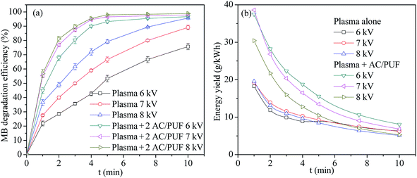 | ||
| Fig. 4 (a) The effect of input voltage on MB degradation efficiency (b) energy yield versus time at different voltage (2 AC/PUF: two pieces of AC/PUF). | ||
The energy yield Y (g kW−1 h−1) was introduced to illustrate the energy efficiency during MB degradation process. It can be clearly seen in Fig. 4b that the energy yield in the coupled system was larger than that in sole system at all the three voltage. The largest energy yield was up to 38.3 g kW−1 h−1 at 7 kV after 1 min treatment for the coupled system. Moreover, the results indicated that the energy yield gradually decreased with the increasing degradation time under every operation condition. The reason was that MB concentration gradually decreased with the increasing degradation efficiency over time, resulting in a lower collision probability between MB molecules and plasma active species, which finally led to less MB removal per unit of energy consumption in reaction system. In addition, energy yield decreased with increasing input voltage, suggesting that an appropriate voltage was needed to acquire largest energy efficiency of degradation system. Considering both degradation efficiency and energy yield, the input voltage of 7 kV was used in the following experiments.
3.3 The effect of initial solution concentration on MB degradation
The effect of initial MB solution concentration on degradation efficiency by plasma reactor and the coupled system was displayed in Fig. 5. For both systems, the MB degradation efficiency at lower initial MB concentration was higher than that at higher initial MB concentration after 10 min treatment. The main reason lied in the fact that the amount of plasma active species formed in the discharge process was maintained at specific concentration level for the constant energy input. It can be also noted that the MB degradation efficiency with plasma alone reached 97.5%, 96.5% and 89.2% with only 10 min treatment time for three initial MB concentration (50 ppm, 75 ppm, 100 ppm), respectively. It proved that the proposed plasma reactor is effective for MB degradation. Moreover, MB degradation efficiency in the coupled system was obviously higher than that in plasma reactor at every initial solution concentration, which was attributed to the addition of AC/PUF.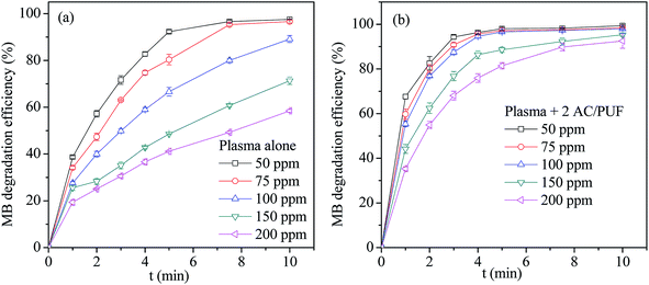 | ||
| Fig. 5 The effect of initial concentration on MB degradation efficiency by (a) plasma reactor alone and (b) the coupled system (2 AC/PUF: two pieces of AC/PUF). | ||
3.4 MB degradation kinetics
Fig. 6 showed MB degradation efficiency by plasma or AC/PUF alone and the coupled system with different pieces of AC/PUF. It can be observed that MB can be partly adsorbed by AC/PUF due to its great adsorption capacity. In addition, the MB degradation efficiency was significantly increased in the presence of AC/PUF in plasma reactor, which can be attributed to the adsorption capacity of AC/PUF and decomposition of pollutants in active sites.22 It was noteworthy that increasing amount of AC/PUF enhanced the MB degradation efficiency. After 5 min treatment, the MB degradation efficiency reached 88.5% with one piece AC/PUF and 96.5% with two pieces of AC/PUF coupled into plasma reactor, while it was only 66.6% with plasma alone. In a word, the coupled system can largely reduce treatment time to achieve the same degradation efficiency, which finally enhanced energy efficiency of plasma treatment.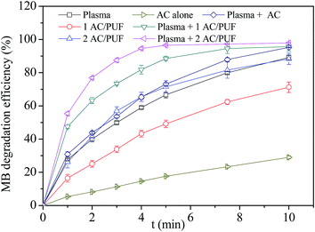 | ||
| Fig. 6 Comparison of plasma alone, AC/PUF alone and the coupled system (initial solution concentration = 100 ppm, input voltage = 7 kV, 1/2 AC/PUF: one/two pieces of AC/PUF). | ||
Additionally, MB degradation efficiency by activated carbon with or without plasma was also investigated. The amount of AC used was equal to that supported on two pieces of AC/PUF. As shown in Fig. 6, compared with AC/PUF, the MB degradation efficiency was obviously lower when AC was used. It was mainly because AC was distributed unevenly in MB solution without being supported on PUF, which caused inadequate contact between pollutants and carbon media and hence the decrease in MB degradation efficiency. The PUF material had advantages of large specific surface, high porosity, small pressure drop, good transport properties and low cost. The combination of carbon and PUF can effectively improve the contact between pollutants and carbon.
In order to compare the degradation rate of different treatment methods, degradation kinetic parameters were determined. The degradation of MB can be described by pseudo first-order kinetics.11 As shown in Table 2, the correlation coefficients were obtained by plotting ln(C0/C) versus time. The highest k value (0.6794 min−1) was obtained when introducing two pieces of AC/PUF into degradation system. The kinetic constant of the coupled system with 2 AC/PUF was 3.18 times that with plasma alone and 3.21 times that with 2 AC/PUF adsorption alone. In addition, the kinetic constant of the coupled system with AC/PUF was larger than that with AC, which suggested more effective MB degradation by plasma coupled with AC/PUF. According to eqn (5), it can be observed that the kinetic constant of MB degradation in plasma reactor coupled with AC/PUF was higher than the sum of that by plasma alone and adsorption alone (SF > 1). It indicated that plasma and AC/PUF in the coupled system had a good synergistic effect in MB degradation.
 | (5) |
| k (min−1) | R2 | SF | G50 (g kW−1 h−1) | |
|---|---|---|---|---|
| AC | 0.0321 | 0.9980 | — | — |
| 1 AC/PUF | 0.1234 | 0.9965 | — | — |
| 2 AC/PUF | 0.2115 | 0.9873 | — | — |
| Plasma + 0 AC/PUF | 0.2135 | 0.9970 | — | 11.6 |
| Plasma + AC | 0.2970 | 0.9891 | 1.2093 | 16.2 |
| Plasma + 1 AC/PUF | 0.4095 | 0.9885 | 1.2155 | 24.7 |
| Plasma + 2 AC/PUF | 0.6794 | 0.9954 | 1.5986 | 38.3 |
3.5 Comparison of various treatment methods
Further comparative experiments were conducted to investigate the synergistic effect of plasma and AC/PUF in the coupled system. MB solution was treated by plasma discharge for certain time (5 min, 10 min, 20 min or 30 min), followed by the addition of two pieces of AC/PUF to adsorb MB molecules or intermediates for the same time.The degradation efficiency and COD removal for various treatment methods are shown in Fig. 7. Both MB degradation efficiency and COD removal by plasma coupled with AC/PUF for 5 min were significantly larger than sum of that by plasma treatment for 5 min followed by AC/PUF adsorption for another 5 min. It indicated that certain synergistic effect existed for the combination of plasma and AC/PUF. The degradation efficiency of 100 ppm MB solution could reach 97.9% with only 10 min treatment in the coupled system, which was close to that obtained by plasma treatment alone for 30 min (97.5%). In addition, the COD removal in the plasma and AC/PUF coupled system was much higher than that obtained by plasma treatment followed by AC/PUF adsorption. It was also possibly due to existence of the synergistic effect. The dissolved ozone generated by plasma discharge was more easily decomposed to ˙OH at the presence of AC/PUF,27 which enhanced the decomposition of MB molecules and its intermediates. Guo et al.28 investigated a hybrid gas–liquid discharge plasma system coupled with granular activated carbon for bisphenol A degradation. Decreasing ozone and increasing ˙OH concentration was observed after the addition of activated carbon under plasma discharge, which illustrated ozone can be catalyzed by activated carbon and converted into ˙OH. Possible mechanism can be described by the following reactions (6)–(10):9
| O3 + H–AC/PUF–H → AC/PUF–O + H2O2 | (6) |
| O3 + AC/PUF–OH → ˙O2–AC/PUF + ˙OH | (7) |
| O3–AC/PUF → O2 + ˙O–AC/PUF | (8) |
| O3 + ˙O–AC/PUF → ˙O2 + O + AC/PUF | (9) |
| ˙OH + intermediates → CO2 + H2O | (10) |
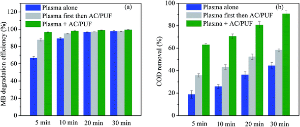 | ||
| Fig. 7 Comparison of the effect of different treatment methods on (a) MB degradation efficiency, and (b) COD removal (initial solution concentration = 100 ppm, input voltage = 7 kV). | ||
The interaction between plasma and AC/PUF improved the MB degradation and mineralization. Moreover, the activated carbon can provide more concentrated centers for oxidation of pollutants by reactive species.9 In a word, the coupled system of plasma with AC/PUF had good synergistic effect, indicating its potential for dyeing wastewater treatment.
The energy yields by plasma alone and the coupled system were as high as 9.3 and 13.5 g kW−1 h−1, respectively. As shown in Table 3, the results were much larger than those reported in previous studies. Furthermore, in order to avoid interference from intermediates at MB degradation efficiency of higher than 50%, energy yield at 50% degradation (G50) was adopted. Aziz et al.16 reported the energy yield for 50% conversion of MB using different AOPs in the range of 0.13 and 20.5 g kW−1 h−1. As listed in Table 2, the highest G50 (38.3 g kW−1 h−1) was obtained by plasma coupled with two pieces of AC/PUF, which was relatively high compared with other studies,15,17 suggesting great energy efficiency of the coupled system.
| Pollutants | Type of operation condition | Conditions | Energy yield (g kW−1 h−1) | Ref. |
|---|---|---|---|---|
| a V0: liquid volume; C0: initial concentration; t: treatment time; V: input voltage; F: input frequency; ACF: activated carbon fiber. | ||||
| Methylene blue | Plasma | V0: 0.1 L, C0: 100 ppm, t: 5 min, power: 8.6 W, air: 1.5 L min−1 | 9.3 | This study |
| Methylene blue | Plasma + AC/PUF | V0: 0.1 L, C0: 100 ppm, t: 5 min, power: 8.6 W, air: 1.5 L min−1 | 13.5 | This study |
| Triclosan | DBD + ACF | V0: 0.12 L, C0: 10 ppm, t: 18 min, power: 60 W | 6.2 | 22 |
| Triclocarban | DBD + TiO2/ACF | V0: 0.1 L, C0: 10 ppm, t: 30 min, power: 38 W, air: 0.4 L min−1 | 0.045 | 23 |
| Methyl orange | Pulsed discharge + ACF | V0: 0.2 L, C0: 80 ppm, t: 21 min, V: 46 kV, F: 100 Hz, air: 1 L min−1 | 4.7 | 29 |
3.6 Repeated use of AC/PUF samples
Repeated use of AC/PUF was important to its applicability for wastewater treatment. The recycling experiment was conducted by reusing AC/PUF for five times. As clearly seen in Fig. 8a, little change in the degradation efficiency of MB was observed with recycle times, suggesting the stability of AC/PUF adsorption capacity under plasma. In addition, recycling experiments of two pieces of AC/PUF alone without plasma for MB removal were also conducted. As shown in Fig. 8b, the MB removal efficiency was dramatically decreased after five cycles, which was mainly due to the reduced adsorption capacity of AC/PUF. By comparison, the MB degradation efficiency with the coupled method was slightly decreased from 97.9% to 96.6% after five runs. It can be ascribed to the self-regeneration of AC/PUF resulting from the degradation of pollutants adsorbed on AC/PUF by active species such as ˙OH. In addition, the COD removal of MB solution was slightly reduced from 70.6% to 66.7% after five runs in the coupled system. Therefore, the method of plasma coupled with AC/PUF has potential for practical application.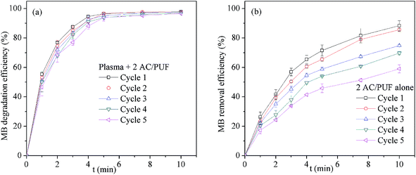 | ||
| Fig. 8 Effect of repeated use of AC/PUF on MB removal efficiency (a) Plasma + 2 AC/PUF, (b) 2 AC/PUF alone (2 AC/PUF: two pieces of AC/PUF). | ||
3.7 Degradation mechanism
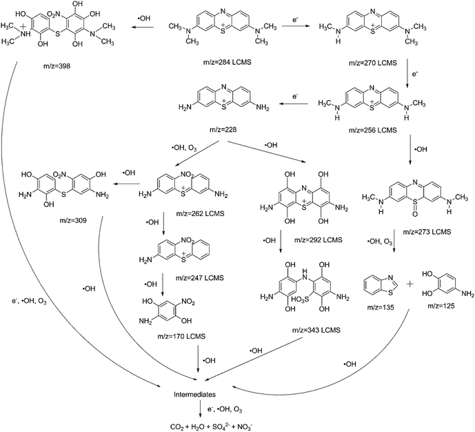
In order to investigate the degradation mechanism of MB using plasma with and without AC/PUF, LC-MS was used to explore the possible degradation intermediates. The results showed little difference in degradation intermediates between plasma treatment with and without AC/PUF. The intermediates were mainly produced by high-energy electron attack, ozonation and hydroxylation. Similar results were reported by Wang et al.30 Possible pathway was put forward as shown in Fig. 9. The existence of MB molecule was confirmed by peak at m/z of 284. With the presence of high-energy electrons, MB molecule was converted into fragments with peaks at m/z of 270, 256, 228, which were attributed to demethylation. In addition, hydroxyl radicals were widely acknowledged as the main species to degrade MB molecules. The organics with m/z of 292 and 343 were determined by LCMS, which was due to hydroxylation reaction.13 Huang et al. proposed the mechanism of MB degradation by plasma treatment based on the bond dissociation energy theory.31 The lower the bond dissociation energy was, the easier the bond was broken. The bond energy of CH3–N(CH3)C6H5 and C6H5–S–C6H5 was calculated to be only 70.8 and 76 kcal mol−1, respectively. Thus, the compound with peaks at m/z of 273, 262, 247 were determined. Additionally, possible ring breaking products (m/z = 170, 135, 125) were proposed, which can be arised from hydroxyl radicals and ozone. The possible intermediates of MB decomposition can be ionic by-products such as acetate, oxalate, and sulfate.16 Finally, all of the intermediates were decomposed and mineralized into CO2, H2O, SO42− and NO3−. Different from plasma alone, compounds with peaks at m/z = 398 and 309 were also found for the coupled system, which can be attributed to the generation of more hydroxyl radicals with the presence of AC/PUF in plasma reactor.4. Conclusions
In this paper, MB degradation was investigated in a novel DBD plasma reactor coupled with a commercial material AC/PUF. The results revealed that MB molecules can be effectively degraded in the plasma reactor. The degradation efficiency increased from 89.2% to 95.7% and 97.9% when one piece and two pieces of AC/PUF were added into the plasma reactor, respectively. The coupled system of plasma and AC/PUF exhibited much better MB degradation effect than plasma coupled with AC. In addition, high COD removal (90.7%) and G50 value (38.3 g kW−1 h−1) were obtained in the coupled system of plasma and AC/PUF. Kinetic study and comparison experiments of different treatment methods indicated the coupled system had a good synergistic effect in MB degradation. Moreover, the AC/PUF can be repeatedly used for five times with negligible change, suggesting good utilization potential. Finally, high energy electron, ozone and hydroxyl radical were acknowledged as the main species in MB degradation.Conflicts of interest
There are no conflicts to declare.References
- W. Li, B. Mu and Y. Yang, Bioresour. Technol., 2019, 277, 157–170 CrossRef CAS PubMed.
- V. Katheresan, J. Kansedo and S. Y. Lau, J. Environ. Chem. Eng., 2018, 6, 4676–4697 CrossRef CAS.
- M. Tichonovas, E. Krugly, V. Racys, R. Hippler, V. Kauneliene, I. Stasiulaitiene and D. Martuzevicius, Chem. Eng. J., 2013, 229, 9–19 CrossRef CAS.
- J. L. Wang and L. J. Xu, Crit. Rev. Environ. Sci. Technol., 2012, 42, 251–325 CrossRef CAS.
- K. Paździor, L. Bilińska and S. Ledakowicz, Chem. Eng. J. DOI:10.1016/j.cej.2018.12.057.
- P. A. Pekakis, N. P. Xekoukoulotakis and D. Mantzavinos, Water Res., 2006, 40, 1276–1286 CrossRef CAS PubMed.
- M. Peña, M. Coca, G. González, R. Rioja and M. T. García, Chemosphere, 2003, 51, 893–900 CrossRef.
- A. Babuponnusami and K. Muthukumar, J. Environ. Chem. Eng., 2014, 2, 557–572 CrossRef CAS.
- B. Jiang, J. Zheng, S. Qiu, M. Wu, Q. Zhang, Z. Yan and Q. Xue, Chem. Eng. J., 2014, 236, 348–368 CrossRef CAS.
- P. Bruggeman and C. Leys, J. Phys. D: Appl. Phys., 2009, 42, 53001 CrossRef.
- K. H. Hama Aziz, H. Miessner, A. Mahyar, S. Mueller, D. Kalass, D. Moeller and K. M. Omer, Sep. Purif. Technol., 2019, 216, 51–57 CrossRef CAS.
- E. S. M. Mouele, J. O. Tijani, O. O. Fatoba and L. F. Petrik, Environ. Sci. Pollut. Res., 2015, 22, 18345–18362 CrossRef CAS PubMed.
- L. O. d. B. Benetoli, B. M. Cadorin, V. Z. Baldissarelli, R. Geremias, I. G. de Souza and N. A. Debacher, J. Hazard. Mater., 2012, 237–238, 55–62 CrossRef CAS PubMed.
- A. S. Bansode, S. E. More, E. A. Siddiqui, S. Satpute, A. Ahmad, S. V. Bhoraskar and V. L. Mathe, Chemosphere, 2017, 167, 396–405 CrossRef CAS PubMed.
- P. Manoj Kumar Reddy, B. Rama Raju, J. Karuppiah, E. Linga Reddy and C. Subrahmanyam, Chem. Eng. J., 2013, 217, 41–47 CrossRef CAS.
- K. H. Hama Aziz, A. Mahyar, H. Miessner, S. Mueller, D. Kalass, D. Moeller, I. Khorshid and M. A. M. Rashid, Process Saf. Environ. Prot., 2018, 113, 319–329 CrossRef CAS.
- G. Iervolino, V. Vaiano and V. Palma, Sep. Purif. Technol., 2019, 215, 155–162 CrossRef CAS.
- L. Wu, Q. Xie, Z. Wu, T. Zheng, X. Lu, M. Lu, Y. Nie and J. Ji, Desalin. Water Treat., 2018, 131, 272–281 CrossRef CAS.
- B. Jiang, J. Zheng, X. Lu, Q. Liu, M. Wu, Z. Yan, S. Qiu, Q. Xue, Z. Wei, H. Xiao and M. Liu, Chem. Eng. J., 2013, 215–216, 969–978 CrossRef CAS.
- Y. Zhang, J. Zheng, X. Qu and H. Chen, J. Colloid Interface Sci., 2007, 316, 523–530 CrossRef CAS PubMed.
- G. Qu, D. Liang, D. Qu, Y. Huang, T. Liu, H. Mao, P. Ji and D. Huang, Chem. Eng. J., 2013, 228, 28–35 CrossRef CAS.
- L. Xin, Y. Sun, J. Feng, J. Wang and D. He, Chemosphere, 2016, 144, 855–863 CrossRef CAS PubMed.
- J. Wang, Y. Sun, J. Feng, L. Xin and J. Ma, Chem. Eng. J., 2016, 300, 36–46 CrossRef CAS.
- E. E. Baldez, N. F. Robaina and R. J. Cassella, J. Hazard. Mater., 2008, 159, 580–586 CrossRef CAS PubMed.
- L. Lefebvre, G. Agusti, A. Bouzeggane and D. Edouard, Catal. Today, 2018, 301, 98–103 CrossRef CAS.
- Y. Nie, Q. Zheng, X. Liang, D. Gu, M. Lu, M. Min and J. Ji, Environ. Sci. Technol., 2013, 47, 7934–7939 CrossRef CAS PubMed.
- U. Jans and J. Hoigné, Ozone: Sci. Eng., 1998, 20, 67–90 CrossRef CAS.
- H. Guo, N. Jiang, J. Li and Y. Wu, Vacuum, 2018, 156, 402–410 CrossRef CAS.
- Y. Zhang, B. Sun, S. Deng, Y. Wang, H. Peng, Y. Li and X. Zhang, Chem. Eng. J., 2010, 159, 47–52 CrossRef CAS.
- B. Wang, B. Dong, M. Xu, C. Chi and C. Wang, Chem. Eng. Sci., 2017, 168, 90–100 CrossRef CAS.
- F. Huang, L. Chen, H. Wang and Z. Yan, Chem. Eng. J., 2010, 162, 250–256 CrossRef CAS.
| This journal is © The Royal Society of Chemistry 2019 |

