 Open Access Article
Study on noise-vibration coupling characteristics of premixed methane–air flame propagation in a tube with an acoustic absorption material
Quan Wang *abc,
Weida Chang
 a,
Shanghao Liu
 a,
Zhimin Li
 a and
Kaibo Zhu
 a
a
aSchool of Chemical Engineering, Anhui University of Science & Technology, Huainan 232001, China. E-mail: wqaust@163.com
bPostdoctoral Mobile Research Station for Civil Engineering, Anhui University of Science & Technology, Huainan 232001, China
cEngineering Laboratory of Explosive Materials and Technology of Anhui Province, Huainan 232001, China
First published on 10th September 2019
Abstract
To study the influence of an acoustic absorbing material (AAM) on the noise and vibration of a methane–air deflagration flame in a square plexiglass tube, a high-speed video camera, pressure sensors, and a noise and vibration tester were used to test the deflagration flame propagation velocity, deflagration pressure, noise and wall vibration characteristics in the tube. The tube length is 540 mm with a cross section of 80 × 80 mm2, and its wall thickness is 12 mm. The experimental results indicate that under the conditions of 8.96% CH4 by volume and fixed repeating obstacles, the built-in AAM of polyester fiber cotton can reduce the peak velocity of the deflagration flame propagation by 11.3%. In addition, the average maximum sound pressure level of the deflagration flame noise is decreased by 17.6%, and the peak vertical vibration velocity of the tube outer wall is decreased by 85.6%. Therefore, using AAM can effectively attenuate the flame propagation and its harmful effects. For the case with an AAM, the flame propagation velocity and deflagration pressure reached the maximum values at 33 ms after ignition, and the values were 62.50 m s−1 and 27.74 kPa, respectively. Similarly, the time history curves of the noise and the tube wall vibration caused by deflagration presented certain correlations. The experimental results and analysis in this paper provide reference values for controlling the hazards of gas explosions in underground mines and other combustible gases in industrial pipelines.
1. Introduction
More than 90% of coal mines are exploited by artificial mining in China. Moreover, with increasing mining depth, coal mine disasters often occur. More than 85% of accidents are caused by gas explosion, which leads to serious casualties and large property loss.1,2 To study gas explosions in a coal mine, a large experimental pipeline can be established, and a small experimental pipeline can also be established. Small experimental pipelines are widely used by many scholars because of their low cost and simple structure in the laboratory. Although the environment of the tube is quite different from that of a real mine roadway, the mechanism of flame propagation is consistent with the two cases.When a gas explosion occurs in the mine, all kinds of electromechanical devices become obstacles in the roadway, which intensifies the flame propagation; Boeck,3 Karanam,4 Na'inna5 and Hall et al.6 investigated the effects of the blockage ratio, position, number and shape of obstacles on flame propagation velocity, overpressure and induced flame turbulence via experimental tests and numerical simulations. The structure of a roadway is complex. A roadway contains all kinds of corners and branches that directly affect the characteristics of flame propagation. Blanchard,7 Frolov,8 Lin9 and Bragin et al.10 studied the effect of bifurcation types, angle size and complex structure of the roadway on the flame propagation velocity, overpressure, induced flame turbulence and impact ignition in tubes. Generally, a large amount of coal dust is deposited in laneways. Shock waves will cause a “gas and coal dust explosion” when the explosion happens,11 which is more serious than a pure gas explosion. Wang et al.12 researched the flame propagation characteristics of gas deflagration when the coal was placed in the pipeline and preliminarily discussed the mechanism of coal dust acceleration on gas flame propagation.
Once a gas explosion occurs in a mine, it is particularly important to take effective measures to reduce or suppress the explosion. Nie,13 Nian,14 Vasil'Ev15 and Babkin et al.16 investigated the effect of AAM on the flame propagation velocity and overpressure in a pipeline and analyzed the effect of the physical structure of the porous media on the quenching flame. Zhang et al.17 inserted tubes made of AAM into smooth rigid wall tubes to study the effects of three different L/D (i.e., 3.85, 7.69 and 15.38) porous-wall tubes on detonation propagation under near-limit conditions. At the same time, it is concluded that with the increase of the length of porous materials, the inhibition of detonation propagation by porous materials is more obvious. Mehrjoo et al.18 studied the detonation structure characteristics of C2H2/O2 and C2H2/N2O mixtures in pipes of different diameters, and explored the suppression mechanism of transverse waves by installing porous walls in pipes. Bivol et al.19 investigated the attenuation of detonation velocity and detonation pressure of hydrogen/air mixture by attaching different thickness AAM to the inner wall of the pipeline.
Gas explosion not only causes destructive overpressure and high temperature burning but also produces noise and vibration, and sound waves cause dynamic instability in the flame propagation. Searby20 noted that the disturbance of acoustic waves would disturb the flame flow field and cause instability in flame propagation. Liu et al.21 investigated the thermo acoustic oscillation of a premixed flame in the combustion chamber and studied the coupling effects among the surface area of the flame, the combustion noise and the pressure oscillation. At present, there are few reports on the coupling characteristics of noise and vibration on flame propagation in small pipes with AAM conditions. Therefore, it is necessary to carry out this research work. In this paper, the experimental results and analysis can provide important technologies which support for the prevention and control of gas explosion hazards in coal mines and other industrial pipelines.
2. Experimental
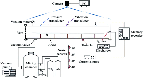
The experimental equipment in this paper consisted of a square plexiglass tube, a gas distribution system, an ignition device, a high-speed camera, pressure sensors, a vibration and noise tester, a data acquisition instrument, AAM and obstacles, etc., as shown schematically in Fig. 1.2.1. Experimental tube
The plexiglass tube length is 540 mm with a cross section of 80 × 80 mm2, and its wall thickness is 12 mm. The ignition end of the tube is closed, and the other end is a silicon rubber sheet.2.2. Gas mixing device
The required concentration of premixed gas is configured by the Dalton partial pressure law. Furthermore, the accurate volume concentration of methane gas is measured by an optical interferometric methane detector (Model CJG10, Shanxi, China), and the experimental volume concentration of methane is 8.96%.The required concentration of premixed gas is configured by the Dalton partial pressure law. To ensure homogeneity of premixed gas, methane and air were mixed for 3 hours in gas distribution tank. The initial pressure of premixed gas in the pipe is 1 atm.
Furthermore, the accurate volume concentration of methane gas is measured by an optical interferometric methane detector, and the experimental volume concentration of methane is 8.96%.
2.3. Ignition device
The ignition system consisted of a simple capacitive energy storage spark ignition device. The exact spark energy value was measured using a special instrument. For convenience, the nominal ignition energy can be used to reflect the ignition energy according to the following formula:
 | (1) |
Based on the calculations, the nominal ignition energy was 14 J. However, the actual spark discharge voltage were smaller than the ideal values in our experiments. There are some factors such as ineffective resistance in the circuit of electric ignition equipment, which results in the smaller actual ignition energy. The actual ignition energy was 250–500 mJ.
2.4. Image acquisition device
An NAC Memrecam HX-3 high-speed camera was used to shoot the whole process of flame propagation, and the shooting rate was set to 4000 fps.2.5. Pressure transducers
The pressure was measured by two piezoelectric pressure sensors (Model CY-YD-205, Sinocera Piezotronics, Inc., Yangzhou, China). During installation, the sensitive faces of the sensors were kept flush with the tube inner wall, and they were calibrated dynamically in a shock tube before use.2.6. Vibration transducers and noise transducers
UBOX5016 was used to measure the vibration speed on the upper wall of the tube (including 3 directional components).Four SZ4A noise sensors were used to test the air noise caused by the deflagration. The measurement points were arranged horizontally and perpendicular to the axis of the pipe. The noise sensors were fixed at distances of 50, 100, 150 and 200 cm from the tube. The noise sensors were calibrated with a HS6020 calibrator before use.
2.7. Obstacles and acoustic absorption material
Acoustic absorption material (AAM) is soft, non-toxic, tasteless, and not easy to rot, with good fire resistance and noise absorption. AAM can be installed in the building wall ceiling and other places, and also can be used for reducing cabin and engine room noise and heat. It is widely used in industrial production and daily life and the production cost of AAM is very low.The AAM22 is composed of polyester fiber. It is a porous material with sizes of 522 × 78 × 17 mm3, porosity of 95–98% and density of 0.021 g cm−3. The diameter of the hole in the AAM covers range from 0.05 mm to 0.1 mm. AAM was attached over the barriers in the tube, as shown in Fig. 2(a).
To aggravate the flame propagation process, an obstacle that consisted of 5 pieces of copper rectangular barriers was placed in the tube. The size of a single barrier is 77 × 30 mm2, and the thickness is 0.5 mm. The barriers were fixed at distances of 100 mm from each other. Moreover, the distance from the first barrier to the spark is 92.6 mm. The obstacle is shown in Fig. 2(b).
3. Results and discussion
3.1. Analysis of high-speed images of methane–air premixed flame propagation in the tube under different conditions
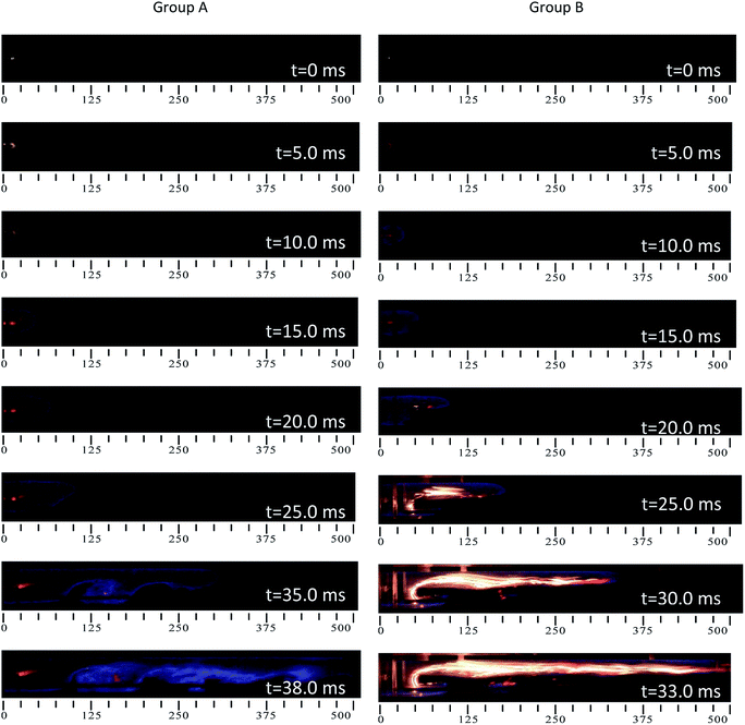
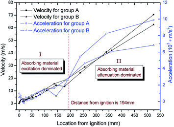
To analyze the effect of AAM on the propagation of the flame in the tube, the experiment was conducted in two situations: (1) in group A, only the obstacle was placed in the tube, and (2) in group B, AAM and the obstacle were placed in the tube. The two conditions were shot by a high-speed camera. The pictures of the typical flame at different times are shown in Fig. 3.In Fig. 3, the flame in group A is blue, while the flame in group B shows strong light. The reason is that AAM surfaces are unsmooth and with combustible filaments. While the flame skimmed over these uneven surfaces, it would produce a local turbulent flame on the surfaces, leading to AAM surfaces' filaments burning, resulting in AAM dominating combustion with yellow flames. Fig. 3 indicates that the durations for the flames in group A and group B to travel from the ignition end to the other end are 38.0 ms and 33.0 ms, respectively. It seems that AAM is unable to inhibit the spread of the flame, but this is not the case. The influence of AAM on the gas premixed flame propagation process was studied further. As shown in Fig. 4, by tracking the outer contour of the high-speed photographs of the deflagration flame, the velocity and acceleration of the flame propagation at different positions were obtained.
3.2. Analysis of methane–air premixed flame propagation velocity and acceleration in the tube under different conditions
As shown in Fig. 3 and 4, the velocity and acceleration of the flame propagation of group B are slightly higher than those of group A, within the range of 194 mm from the ignition end (region I). This result indicates that AAM has not shown an attenuation effect at the initial stage of flame propagation but has a certain incentive effect on flame propagation. AAM mainly acts as an obstacle at the initial stage of flame propagation, which increases the degree of flame propagation turbulence and intensifies the chemical reaction, leading the initial flame propagation velocity to increase slightly. With continued propagation of the flame, the flame acceleration of group A becomes close to that of group B and then exceeds that of group B. When the distance of the flame propagation exceeds 194 mm (region II), the effect of AAM on the flame propagation attenuation begins to show. When the flame propagation distance is greater than 305 mm, the flame propagation velocity of group B is less than that of group A, and the peak flame propagation velocities of groups A and B are 70.50 m s−1 and 62.50 m s−1, respectively. Moreover, AAM reduced the peak of flame propagation velocity by 11.3%. However, AAM showed a certain incentive effect on flame propagation in the initial stage, and the length of the experimental tube is short, leading to an increase in the average velocity of group B. When the distance of flame propagation exceeds 194 mm, AAM has an obvious attenuation effect on the flame propagation. Therefore, it can be foreseen that when the tube is sufficiently long, AAM can effectively attenuate gas deflagration propagation.3.3. Analysis of the flame pressure and flame propagation velocity in the tube under condition B
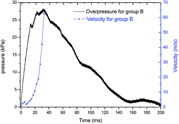
The experimental results show that there is a certain coupling relationship between the gas deflagration pressure curve and the flame propagation velocity curve in groups A and B. The analysis of the group B condition is taken as an example. Fig. 5 shows that the flame propagation velocity curve fluctuates at 5 ms after ignition and that the deflagration pressure curve fluctuates at 13 ms after ignition, indicating that the instability of flame propagation will cause the delayed oscillation of deflagration pressure. The unsteady combustion of the premixed gas caused the fluctuation of flame propagation velocity and deflagration pressure. The reason was that obstacles and AAM presented the blockage effects to flame propagation at the early stage of flame growing. Then, the flame front was twisted and draped while passing through the surface of obstacles and AAM. The small scale vortexes evolved into the large scale vortexes, enhancing the turbulence intensity. However, the obstacles mainly play the incentive effect on the flame propagation, while AAM mainly shows the inhibition. This opposite effects result in the combustion instability. At 33 ms after ignition, the peak of the flame propagation velocity and the deflagration pressure are 62.5 m s−1 and 27.74 kPa, respectively. Therefore, under the experimental conditions, there is a certain correlation between the flame propagation velocity and the deflagration pressure in the tube, or there is a certain coupling relationship between the flame propagation velocity and the deflagration pressure.3.4. Analysis of the flame pressure and flame propagation velocity in the tube under condition B
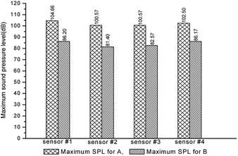
Fig. 6 shows the sound pressure level histograms measured by four noise sensors for the experimental conditions of group A and group B. For group A, the maximum sound pressure levels of four sensors (#1–4) are 104.66, 100.57, 100.57, and 102.50 dB, respectively. For group B, the maximum sound pressure levels of the four sensors (#1–4) are 86.20, 81.40, 82.57, and 86.17 dB, respectively. It can be demonstrated that the maximum sound pressure levels of group B decrease by 17.6%, 19.1%, 17.9% and 15.9%, respectively, compared with those of group A, and the average maximum sound pressure level of deflagration flame noise decreases by 17.6%. Therefore, AAM can effectively reduce the deflagration flame noise.3.5. Analysis of the vibration of the tube wall in the tube under different conditions
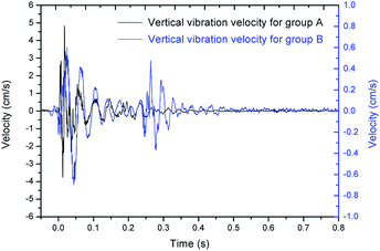
Considering that the vertical direction of the outer wall of the tube is more obvious and easier to measure, a vibration sensor is set on the outer wall of the tube to test the vibration time curve of the tube wall, as shown in Fig. 7.As shown in Fig. 7, for group A, the maximum vertical vibration velocity of the tube wall is 4.842 cm s−1, and the duration of vibration is 0.782 s. For group B, the maximum vertical vibration velocity of the tube wall is 0.695 cm s−1, and the duration of vibration is 0.472 s. The peak value vibration velocity of the tube wall of group B is 85.6% lower than that of group A, which indicates that AAM can effectively reduce the vibration. The vibration time history curve of group B appears to be the “secondary rising pulsation” phenomenon. After the deflagration flame rushes out of the tube, the sparse wave rolls up the AAM, which causes turbulence to intensify in the tube.
3.6. Analysis of the flame noise and the vibration of the tube wall in the tube under condition B
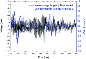
Fig. 8 shows the flame noise and vertical vibration curves of the tube wall in group B. It is noticeable from Fig. 8 that the flame noise caused by the deflagration flame is stronger in the periods of 0–100 ms and 170–275 ms. In the period of 0–100 ms, the noise is mainly caused by deflagration waves in the tube. In the period of 170–275 ms, the noise is caused by the heat released by gas combustion and the disturbance of AAM caused by sparse waves.The flame noise curve has the first violent fluctuation in the period of 0–100 ms, and the peak value of the voltage is 9.16 mv at 28.8 ms. The flame noise curve has a second violent fluctuation at 229 ms after ignition, and its peak value of voltage is −9.46 mv. Meanwhile, the vertical vibration curve of the tube wall has the first violent fluctuation in the period of 0–120 ms, and the peak value of the vibration velocity is 0.689 cm s−1 at 43.4 ms. The vertical vibration curve of the tube wall has a second violent fluctuation at 264 ms after ignition, and its peak value of the vibration velocity is 0.466 cm s−1. Therefore, with the condition of AAM, the development trends of the flame noise curve and the vertical vibration curve of the tube wall are basically the same, in which they all decay from the violent oscillation to the initial state. This result shows that the deflagration flame noise and the vertical vibration of the tube wall have a certain correlation or that there is a certain coupling relationship between the deflagration flame noise and the vertical vibration of the tube wall.
Furthermore, the actual gas explosion is often a process of deflagration, a rapid combustion chemical reaction, and the heat released by the combustion is mostly used to support the propagation of deflagration waves (effective energy),23 with some of the heat absorbed by the tube wall (invalid energy). Moreover, part of the combustion heat is used to arouse noise and cause vibration of the tube wall (invalid energy), and there is a coupling relationship among the flame propagation parameters, noise and vibration of the tube wall. Thus, AAM can attenuate the maximum sound pressure level of deflagration flame noise and attenuate deflagration flame characteristic parameters, tube wall vibration and other harmful effects. This study can provide theoretical support for the passive prevention and control technology of mines for gas explosions.
4. Conclusions
(1) Under the experimental conditions with AAM, the peak velocity of the flame propagation is reduced by 11.3% in the tube compared with that without AAM, and AAM can reduce noise and vibration. The maximum sound pressure level and the peak vibration velocity are reduced by 17.6% and 85.6%, respectively.(2) The experimental results show that for the condition with AAM, the flame propagation velocity is the maximum at 33 ms after ignition in the tube, and the value is 62.5 m s−1. At this time, the deflagration pressure also reaches its maximum, with a value of 27.74 kPa, indicating that there is a certain correlation between the flame propagation velocity and the deflagration pressure.
(3) For the condition with AAM, the trends of the deflagration flame noise and the tube wall vibration curve are basically the same, indicating that there is a certain coupling relationship between noise and tube wall vibration.
Conflicts of interest
There are no conflicts to declare.Acknowledgements
This study was supported by National Natural Science Foundation of China (No. 11872002, No. 11502001), China Postdoctoral Science Foundation Funded Project (No. 2014M561808), and the very useful corrections and suggestions were given by Prof. Chi-Min Shu from YunTech of Taiwan, the authors expressed their sincere gratitude here.References
- L. Yuan, Exploit coal and gas simultaneously lead scientific coal exploration, Ener. Ener. Cons., 2011, 4, 1–4 Search PubMed.
- J. P. Sun, Research of integrated method of prevention and control of gas, Ind. Mine Autom., 2011, 2, 1–5 Search PubMed.
- L. R. Boeck, S. Lapointe, J. Melguizo-Gavilanes and G. Ciccarelli, Flame propagation across an obstacle: OH-PLIF and 2-D simulations with detailed chemistry, Proc. Combust. Inst., 2017, 36(2), 2799–2806 CrossRef CAS.
- Karanam, P. K. Sharma and G. Sunil, Numerical simulation and validation of flame acceleration and DDT in hydrogen air mixtures, Int. J. Hydrogen Energy, 2018, 43(36), 17492–17504 CrossRef CAS.
- A. M. Na'inna, H. N. Phylaktou and G. E. Andrews, Explosion flame acceleration over obstacles: effects of separation distance for a range of scales, Process Saf. Environ. Prot., 2017, 107, 309–316 CrossRef.
- R. Hall, A. R. Masri, P. Yaroshchyk and S. S. Ibrahimb, Effects of position and frequency of obstacles on turbulent premixed propagating flames, Combust. Flame, 2009, 156(2), 439–446 CrossRef CAS.
- R. Blanchard, D. Arndt, R. GräTz, M. Poli and S. Scheider, Explosions in closed pipes containing baffles and 90 degree bends, J. Loss Prev. Process Ind., 2010, 23(2), 253–259 CrossRef.
- S. M. Frolov, V. S. Aksenov and I. O. Shamshin, Shock wave and detonation propagation through U-bend tubes, Proc. Combust. Inst., 2007, 31(2), 2421–2428 CrossRef.
- B. Q. Lin, C. Guo, Y. M. Sun, C. J. Zhu, Y. D. Hong and H. Yao, Effect of bifurcation on premixed methane–air explosion overpressure in pipes, J. Loss Prev. Process Ind., 2016, 43, 464–470 CrossRef CAS.
- M. V. Bragin, D. V. Makarov and V. V. Molkov, Pressure limit of hydrogen spontaneous ignition in a T-shaped channel, Int. J. Hydrogen Energy, 2013, 38(19), 8039–8052 CrossRef CAS.
- S. X. Lu, Z. R. Guo and Y. L. Li, Experimental and theoretical analysis of acceleration of a gas flame propagating over a dust deposit, Proc. Combust. Inst., 2002, 29(2), 2839–2846 CrossRef CAS.
- Q. Wang, Z. W. Shen, Z. R. Guo and H. H. Ma, Flame propagation characteristics for premixed methane–air with coal-dust in square tube, J. China Coal Soc., 2012, 37(10), 1693–1697 Search PubMed.
- B. Nie, X. He, R. Zhang, W. Chen and J. Zhang, The roles of foam ceramics in suppression of gas explosion overpressure and quenching of flame propagation, J. Hazard. Mater., 2011, 192(2), 741–747 CrossRef CAS PubMed.
- W. M. Nian, K. Y. Zhou, C. J. Xia, H. L. Wang and J. F. Ye, The experimental study of strength attenuation of gaseous detonation wave through acoustic absorbing walled channel, Fire Saf. Sci., 2003, 12(2), 84–89 Search PubMed.
- A. A. Vasil'Ev, Near-limiting detonation in channels with porous walls, Combust., Explos. Shock Waves, 1994, 30(1), 101–106 CrossRef.
- V. S. Babkin, A. A. Korzhavin and V. A. Bunev, Propagation of premixed gaseous explosion flames in porous media, Combust. Flame, 1991, 87(2), 182–190 CrossRef CAS.
- B. Zhang, H. Liu and B. Yan, Effect of acoustically absorbing wall tubes on the near-limit detonation propagation behaviors in a methane–oxygen mixture, Fuel, 2019, 236, 975–983 CrossRef CAS.
- N. Mehrjoo, Y. Gao, C. B. Kiyanda, H. D. Ng and J. H. S. Lee, Effects of porous walled tubes on detonation transmission into unconfined space, Proc. Combust. Inst., 2015, 35(2), 1981–1987 CrossRef CAS.
- G. Y. Bivol, S. V. Golovastov and V. V. Golub, Attenuation and recovery of detonation wave after passing through acoustically absorbing section in hydrogen-air mixture at atmospheric pressure, J. Loss Prev. Process Ind., 2016, 43, 311–314 CrossRef CAS.
- S. Geoff, Acoustic instability in premixed flames, Combust. Sci. Technol., 1992, 81, 221–231 CrossRef.
- L. S. Liu, X. Gou, B. Y. Lin, J. Bao and Y. Yuan, Image analysis on thermo-acoustic oscillations of premixed flame, J. Combust. Sci. Technol., 2011, 17(2), 126–132 Search PubMed.
- C. Guo, G. Thomas, J. Li and D. Zhang, Experimental study of gaseous detonation propagation over acoustically absorbing walls, Shock Waves, 2002, 11(5), 353–359 CrossRef.
- Q. Wang, Z. W. Shen, Z. R. Guo, H. H. Ma and C. C. Wang, Influences of nonmetallic powders on premixed methane–air flame propagation in square tube, Explos. Shock Waves, 2013, 33(4), 357–362 CAS.
| This journal is © The Royal Society of Chemistry 2019 |

