 Open Access Article
Enhanced production of aromatics from propane with a temperature-shifting two-stage fluidized bed reactor†
Yifeng Yang,
Yilin Hou,
Zhaohui Chen,
Huiqiu Wang,
Yu Wang ,
Boyang Liu,
Zhuoya Dong,
Jun Gao,
Ran Wei and
Weizhong Qian
 *
*
Department of Chemical Engineering, Tsinghua University, 100084, China. E-mail: qianwz@tsinghua.edu.cn
First published on 23rd August 2019
Abstract
A temperature-shifting two-stage fluidized bed reactor technology was used to convert propane and its intermediate products into aromatics. The first stage served for the aromatization of propane with a Ga/ZSM-5 catalyst at 570 °C. The second stage served for the alkylation of the intermediates of olefins at 300 °C. The increased yield of aromatics was attributed to the effective transformation of C2–C3 olefins as well as due to the suppression of the hydrogen transfer effect of the olefins.
The production of aromatics from propane with zeolite-based catalysts (e.g. HZSM-5, Zn/ZSM-5, and Ga/ZSM-5) is an important route, exhibiting a combined effect of dehydrogenation with a metal and oligomerization, ring formation with Lewis/Brønsted acids, and a shape selective effect inside the channel of the zeolite.1–4,6,7 Increasing the temperature in the range 500–550 °C or above is thermodynamically and kinetically favorable for the conversion of propane in such a slow and endothermic reaction.8–10 However, the dehydrogenation of propane as well as the complicated transformation in the dual hydrocarbon pool cycle inside the zeolite, produces olefins as intermediates.5 These are rapidly converted into paraffins with the same carbon number at a high temperature by an effect of hydrogen transfer, rather than ring formation to aromatics, which is similar to those in methanol-to-aromatics (MTA) or methanol to olefins (MTO) processes.11–13 Such a drawback is difficult to overcome for the case with a long residence time between the catalyst and the gases, for example, in a large reactor with isothermal operation. On the other hand, a multistage fluidized bed reactor was adopted in the MTA process, offering the flexibility of temperature shifting and a variation of catalysts in different stages. As a result, the backmixing of gases could be suppressed effectively to achieve a high conversion of feedstock and a high selectivity of the desired aromatics products.14–17 However, due to the differences in the catalysts, operating temperature, partial pressure of hydrogen or water, and coke type, such a multistage reactor strategy has not been applied to propane to aromatics conversion yet.
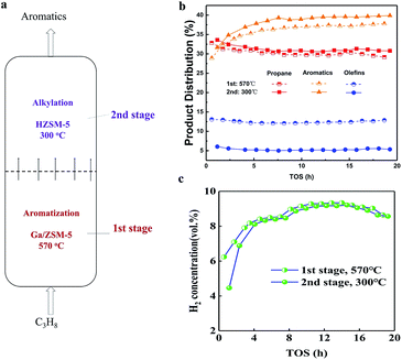
Herein, we propose a temperature-shifting second-stage fluidized bed concept for the consecutive conversion of propane and its intermediate products, as illustrated in Fig. 1. The technology allows for the high conversion of propane with a Ga/ZSM-5 catalyst in the first stage of the reactor (close to the entrance of propane). The as-produced light paraffins and olefins with the as-produced benzene (B) and toluene (T) are further converted into C8–C9 aromatics with an HZSM-5 catalyst in the second stage at a low temperature. As a result, the content of the C2–C3 olefins decreased by 8% from the first stage to the second stage. Meanwhile, the yield of the aromatics after the second stage increased by 6–12% compared with that after the first stage. Our strategy provides new insights into the consecutive conversion chains in the conversion system of propane to aromatics.
Experimentally, 340 g of Ga/ZSM-5 catalyst was used in the first stage of the fluidized bed, where the temperature was 570 °C (ESI, SI-1†). Next, 34 g of HZSM-5 catalyst was packed in the second stage of the fluidized bed, where the temperature was 300 °C. The temperatures in different stages were controlled separately and there was a condenser between them. The feedstock of propane diluted with N2, entering into the fluidized bed from the bottom, was first converted on the Ga/ZSM-5 catalyst in the first stage. Then, the as-produced intermediate product, entering into the second stage, was further converted on HZSM-5. Reactions in the two stages were both carried out in the gaseous state. The pressure of the exit of the reactor was 0.35 MPa. The space velocity of propane on the catalyst in the first stage was 0.01 h−1. In this case, the sampling of gases and catalysts in different stages was performed to understand the process efficiency.
The product distribution after flowing out of the reactor is shown in Fig. 1b. The weight ratio of propane was 30–31% in the first stage and changed to 32–33% for longer times. This suggested that the conversion of propane was close to 70% at 570 °C in the first stage, suggesting that high temperature was favourable for the conversion of propane. For the production of aromatics, there was an apparent induction period of 1–5 h, where the yield of aromatics increased from 28% to 34% in the first stage. This was due to the building of a hydrocarbon pool inside the zeolite, as reported in many other studies.12,13 After that, the yield of aromatics remained very constant at 34–35.5% in the first stage for 5–20 h. Moreover, the yield of olefins remained constant at 13% in the first stage for 20 h. Also, further conversion of olefins in the second stage was also very stable, resulting in a decrease in the yield of olefins to 5% in the second stage for 20 h. The transformation of olefins in the second stage contributed to the increase in the yield of aromatics to 36–39.5% for 20 h. The steady changing trend validated the effectiveness of the enhanced production of aromatics from olefins in situ in the second stage for such a temperature shifting two-stage fluidized bed technology. In addition, the transformation of propane into aromatics yielded hydrogen in a large amount (Fig. 1c). The volume ratio of hydrogen in 1–5 h was smaller than 8%, also confirming the presence of an induction period for the catalyst. After that, the volume ratio of hydrogen exceeded 8–10% in the first stage. The volume ratio of hydrogen only dropped a very small bit in the exit of the second stage, validating the effective suppression of the side reactions at low temperature in the second stage.
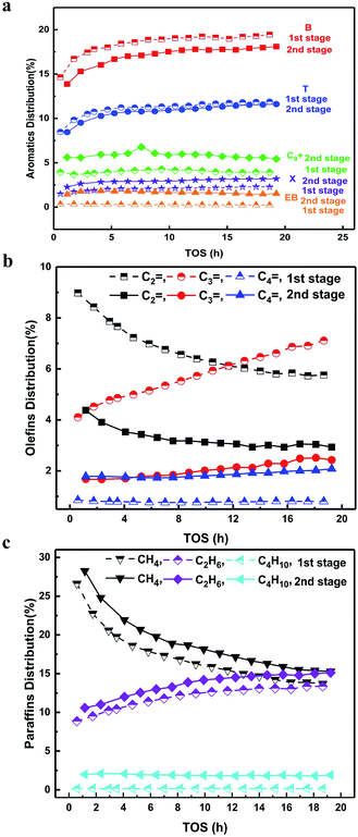
As follows, we analysed the distribution of aromatics in detail (Fig. 2a). The ratio of B was the largest, T was the second largest and xylene (X) was very small. This suggested that the high temperature condition favoured the formation of B and T with few methyl groups on the benzene ring, indicating a dealkylation effect.16,17,20 The yields of B and T showed a much more rapid increasing trend compared to that of X in the induction period, where the coke amount was low and didn't exert a diffusion barrier on these molecules. In this case, the increased yields of B and T were attributed to the altering of the acidic sites with the increased dealkylation ability. The following reactions in the second stage resulted in the decrease in the yields of B and T, but an increase in the yields of X, ethylbenzene (EB) and trimethylbenzene (TriMB). The latter two were apparently the products of alkylation between olefins with B and T.16–19 Quantitatively, the yields of B and T decreased by 2–2.5% and 0.5%, respectively. The yields of X, EB and TriMB increased by 1–1.5%, 2% and 2.5%, respectively. The increased part of X, EB and TriMB was larger than the decreased part of B and T. From the changing trend of olefins (Fig. 2b), it can be found that the yield of ethylene decreased by 4% from the 1st stage to the 2nd stage, while the yield of propene dropped by 2% at 1 h and by 4.5% at 19 h, The yield of butene, however, increased by 1% from the 1st stage to the 2nd stage. This suggested that except for the dominant alkylation of olefins with B and T, the self-aromatization of olefins and the transformation to other intermediates (butene) still occur at low temperatures in the second stage. Although the components of gases entering into the second stage differed with the reaction time, the combined effect of the alkylation and self-aromatization of olefins made the gross yield of aromatics in the second stage nearly constant with the reaction time (Fig. 1a).
In addition, we also compared the hydrogen transfer effect in the different stages (Fig. 2c). The yields of methane, ethane and butane all increased by 1–2% after the transformation in the second stage. Ethane and butane were both the products from ethylene and butene via the hydrogen transfer effect, respectively. As compared to the formation of aromatics from ethylene and the ratio of butene in the second stage, we would like to state that the hydrogen transfer effect still existed but was insignificant in the present study. This validated the effectiveness of the suppression of the hydrogen transfer effect by the use of temperature shifting in the two-stage fluidized bed.
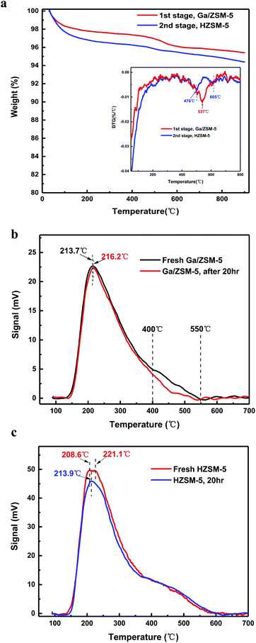
In addition, it is very interesting that the activity of the catalyst for the formation of aromatics was stable for around 20 h, but the activity of produced methane was suppressed sustainably. Quantitatively, the TGA pattern indicated that the catalyst in the first stage and second stages contained 4.5% coke and 5.8% coke, respectively (Fig. 3a). This suggested that both the decreased yields of methane were due to the coke deposition of the catalysts in the different stages. Nearly 5% coke deposition on the catalyst resulted in a decreased yield of methane by 15% within 20 h. This, we think, is therefore a very good method to suppress the undesirable methane, which is inert to further transform and is of low cost in all hydrocarbons. Coke, sometimes, is desirable for the circulating fluidized bed reactor since its burning in the reactor of a regenerating catalyst by air provides the necessary heat for the high temperature for this endothermic reaction.14,21,22 In addition, the derivative thermogravimetric (DTG) pattern (Fig. 3a inset) indicated that there was an apparent peak centre at 537 °C for the coke on the catalysts in the first stage (Fig. 3b). The value was higher than that for the burning temperature of poly-aromatics but close to that for the activated carbon or carbon filaments. In addition, this burning temperature of the coke was higher than the temperature (centre at 476 °C) of the coke at the second stage. This apparently suggests that the coke in the first stage and second stage is significantly different.
We compared the acidic properties (NH3-TPD data) of the catalyst used in the different stages (Fig. 3b and c). There was a strong peak of weak acids for the Ga/ZSM-5 catalyst centred at 213–216 °C, but they remained nearly unchanged before and after the deposition of coke. The difference between the fresh and the coke-deposited Ga/ZSM-5 catalysts mainly comes from the peak intensity between 400–550 °C, assigned to the middle strength or strong acids. This result is reasonable considering the dehydrogenation of propane and the formation of a benzene ring require high temperature and strong acidic sites. In comparison, the HZSM-5 catalyst used in second stage mainly exhibited a difference in the low temperature region (centred at 208–220 °C), assigned to the weak acids.15,18–20 The acid amount of these weak acids dropped significantly after the deposition of coke. This result is also reasonable considering the alkylation of olefins with B/T is relatively easy, for which the weak acids on the catalyst are enough.
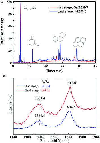
We used CH2Cl2 to extract the coke in the different stages and used GC-MS to analyze the solutions (Fig. 4a). It was clear that there were various peaks observed for the coke in the second stage, which contained sing-, double-, triple-, even tetra-benzene ring derivates. In sharp contrast, there was nearly none of these organic compounds observed with the coke in the first stage. This suggested that the coke was formed by the gradual dehydrogenation of poly-aromatics in the second stage at low temperature with the increase in reaction time.25,26 However, the high temperature in the first stage resulted in a quick dehydrogenation of the poly-aromatics to further become a graphite-type product or amorphous carbon. This well explains the strange trend in the present work that the coke amount at low temperatures (second stage) was higher than that found at high temperature (first stage). In addition, as the remaining temperature was nearly the same in the second stage, olefins in a dry condition (the present study) tended to become coke, compared to that in a wet condition (where the partial pressure of water is very high) in the MTA process.16
 | ||
| Fig. 4 (a) GC-MS chromatograms of the organic species in the catalysts (used for 20 h) extracted by CH2Cl2. (b) Raman spectra of the coke-deposited catalyst for 20 h. | ||
Raman spectroscopy further confirmed this trend (Fig. 4b). For the coke deposited on the catalyst in the first stage, the intensity ratio of the D band to G band was 0.534, larger that (0.455) at the second stage. This suggested the formation of highly graphitized carbon by a serious dehydrogenation. In addition, the peaks of the D band and G band for the coke in the second stage were also very wider compared to those in the first stage, providing direct evidence of the presence of non-crystalline poly-aromatics in the second stage.
Considering the time-dependent total conversion of propane, total selectivity of aromatics, total selectivity of olefins and paraffins, the catalysts in the first and second stages were all very stable within 20 h reaction. It is hard to say that the catalyst was seriously deactivated. Many previous studies have confirmed the low deposition rate of coke on the Ga/ZSM-5 catalyst with high stability.1–4,27 The active sites responsible for the formation of aromatics, for the dehydrogenation of propane and for the surface alkylation of olefins and B/T were all less influenced by the deposition of coke with the increase in the reaction time in the present study, probably owing to the deposition position of the coke.28 However, the coke deposited process changed the profile of ethylene and propene, via different hydrocarbon pools inside the zeolite channel.24,29–33 Further investigation is needed. In addition, the technology is not only useful for the suppression of the hydrogen transfer effect in propane to aromatics, but also for the selectivity control of propene in similar MTA and MTO processes.12,14–17,20–23,26,32 We also summarized the results of the conversion of propane and selectivity of BTX (Table S2, SI-2†). The results were apparently dependent on the operating condition and catalyst. Even though our results (conversion of propane: 70%, selectivity of BTX: 50%) in a fluidized bed with large quantities of catalysts (340 g Ga/ZSM-5 and 34 g HZSM-5) rank in the middle among many data obtained in packed beds with small quantities of catalyst (1 g), they suggest the flow mode of the gases in a two-stage fluidized bed is close to that in a packed bed, validating our original purpose.
In summary, we validated the temperature-shifting second-stage fluidized bed technology for the deep conversion of propane to achieve a high yield of aromatics. Here, two stages served for propane aromatization and the alkylation of olefins (C2–C3) with aromatics in sequence. Olefins were successfully converted into aromatics. Characterization of the coke suggested different dehydrogenation effects in different stages by the temperature effect. The deposition of coke on the catalyst suppressed the formation of methane, but did not influence the gross conversion of propane and the gross yield of aromatics. These results provide new insights into the process intensification technology for propane-to-aromatics conversion.
Conflicts of interest
There are no conflicts to declare.Acknowledgements
The authors thank the support of the National Key Research and Development Program of China (2018YFB0604803). The author was grateful to the experimental assistance of Shuting Zhang, Xiaoru Chen, Lipeng Hou, Tianpeng Li, Shiyong Xing.Notes and references
- H. Kitagawa, Y. Sendoda and Y. Ono, J. Catal., 1986, 101, 12–18 CrossRef CAS.
- V. d. O. Rodrigues and C. F. J. Arnaldo, Appl. Catal., A, 2012, 435–436, 68–77 CrossRef CAS.
- M. S. Scurrell, Appl. Catal., 1988, 41, 89–98 CrossRef CAS.
- M. Raad, A. Astafan, S. Hamieh, J. Toufaily, T. Hamieh, J. D. Comparot, C. Canaff, T. J. Daou, J. Patarin and L. Pinard, J. Catal., 2018, 365, 376–390 CrossRef CAS.
- A. Bhan and W. N. Delgass, Catal. Rev.: Sci. Eng., 2008, 50, 19–151 CrossRef CAS.
- C. Y. Hsieh, Y. Y. Chen and Y. C. Lin, Ind. Eng. Chem. Res., 2018, 57, 7742–7751 CrossRef CAS.
- P. Gao, Q. Wang, J. Xu, G. D. Qi, C. Wang and X. Zhou, ACS Catal., 2017, 8, 69–74 CrossRef.
- M. Raad, S. Hamieh, J. Toufaily, T. Hamieh and L. Pinard, J. Catal., 2018, 366, 223–236 CrossRef CAS.
- M. Corbetta, F. Manenti, C. Pirola, M. V. Tsodikovc and A. V. Chistyakov, Comput. Chem. Eng., 2014, 71, 457–466 CrossRef CAS.
- V. O. Rodrigues, F. J. Vasconcellos Jr and A. C. F. Júnior, J. Catal., 2016, 344, 252–262 CrossRef CAS.
- E. Iglesia and J. E. Baumgartner, Catal. Lett., 1993, 21, 55–70 CrossRef CAS.
- Y. X. Li, M. Y. Zhang, D. Z. Wang, F. Wei and Y. Wang, J. Catal., 2014, 311, 281–285 CrossRef CAS.
- J. S. Martínez-Espín, K. De Wispelaere, T. V. Janssens, S. Svelle, K. P. Lillerud and P. Beato, ACS Catal., 2017, 7, 5773–5780 CrossRef.
- In Multiphase reactor engineering for clean and low-carbon energy applications, ed. W. Z. Qian, F. Wei, Y. Cheng, W. F. Wei and Y. Jin, John Wiley & Sons Inc., 2017, pp. 295–311 Search PubMed.
- T. Wang, X. P. Tang, X. F. Huang, W. Z. Qian, Y. Cui, X. Y. Hui, W. Yang and F. Wei, Catal. Today, 2014, 233, 8–13 CrossRef CAS.
- Z. H. Chen, Y. L. Hou, W. L. Song, D. L. Cai, Y. F. Yang, Y. Cui and W. Z. Qian, Chem. Eng. J., 2019, 371, 639–646 CrossRef CAS.
- Z. H. Chen, Y. L. Hou, Y. F. Yang, D. L. Cai, W. L. Song, N. Wang and W. Z. Qian, Chem. Eng. Sci., 2019, 204, 1–8 CrossRef CAS.
- C. H. Christensen, K. Johannsen, I. Schmidt and C. H. Christensen, J. Am. Chem. Soc., 2003, 125, 13370–13371 CrossRef CAS PubMed.
- N. Hansen, T. Brüggemann, A. T. Bell and F. J. Keil, J. Phys. Chem. C, 2008, 112, 15402–15411 CrossRef CAS.
- J. G. Zhang, W. Z. Qian, C. Y. Kong and F. Wei, ACS Catal., 2015, 5, 2982–2988 CrossRef CAS.
- Refining processes handbook, ed. S. Parkash, Elsevier Inc., 2003 Search PubMed.
- G. Q. Zhang, X. Zhang, T. Bai, T. F. Chen and W. T. Fan, J. Energy Chem., 2015, 24, 108–118 CrossRef.
- K. Shen, W. Z. Qian, N. Wang, C. Su and F. Wei, J. Am. Chem. Soc., 2013, 135, 15322–15325 CrossRef CAS PubMed.
- I. Yarulina, S. Bailleul, A. Pustovarenko, J. R. Martinez, K. D. Wispelaere, J. Hajek, B. M. Weckhuysen, K. Houben, M. Baldus, V. V. Speybroeck, F. Kapteijn and J. Gascon, ChemCatChem, 2016, 8, 3057–3063 CrossRef CAS.
- Y. Q. Song, X. X. Zhu, S. J. Xie, Q. X. Wang and L. Y. Xu, Catal. Lett., 2004, 97, 31–36 CrossRef CAS.
- Y. L. Hou, N. Wang, J. M. Zhang and W. Z. Qian, RSC Adv., 2017, 7, 14309–14313 RSC.
- X. F. Su, G. L. Wang, X. F. Bai, W. Wu, L. F. Xiao, Y. J. Fang and J. W. Zhang, Chem. Eng. J., 2016, 293, 365–375 CrossRef CAS.
- D. L. Cai, Y. L. Hou, C. X. Zhang, N. Wang, Z. H. Chen, W. L. Song, W. Z. Qian and F. Wei, Nanoscale, 2018, 10, 16431–16433 RSC.
- U. Olsbye, S. Svelle, M. Bjorgen, P. Beato, T. V. Janssens, F. Joensen, S. Bordiga and K. P. Lillerud, Angew. Chem., Int. Ed., 2012, 51, 5810–5831 CrossRef CAS PubMed.
- S. Ilias and A. Bhan, J. Catal., 2012, 290, 186–192 CrossRef CAS.
- T. Otto, S. I. Zones and E. Iglesia, J. Catal., 2016, 339, 195–208 CrossRef CAS.
- S. Svelle, F. Joensen, J. Nerlov, U. Olsbye, K. P. Lillerud, S. Kolboe and M. Bjørgen, J. Am. Chem. Soc., 2006, 128, 14770–14771 CrossRef CAS PubMed.
- M. Bjørgen, S. Svelle, F. Joensen, J. Nerlov, S. Kolboe, F. Bonino, L. Palumbo, S. Bordiga and U. Olsbye, J. Catal., 2007, 249, 195–207 CrossRef.
Footnote |
| † Electronic supplementary information (ESI) available. See DOI: 10.1039/c9ra05420k |
| This journal is © The Royal Society of Chemistry 2019 |


