 Open Access Article
Vanadium occupation and its leachability differences in trioctahedral and dioctahedral mica
Qiushi Zheng abc,
Yimin Zhang*abcd,
Nannan Xueabc,
Tao Liuabcd and
Jing Huangabc
aSchool of Resource and Environmental Engineering, Wuhan University of Science and Technology, Wuhan 430081, China. E-mail: zym126135@126.com
bState Environmental Protection Key Laboratory of Mineral Metallurgical Resources Utilization and Pollution Control, Wuhan University of Science and Technology, Wuhan 430081, China
cHubei Collaborative Innovation Center for High Efficient Utilization of Vanadium Resources, Wuhan University of Science and Technology, Wuhan 430081, China
dSchool of Resource and Environmental Engineering, Wuhan University of Technology, Wuhan 430070, China
First published on 2nd September 2019
Abstract
Vanadium in black shale is found mainly in aluminosilicate minerals such as mica. Vanadium occupation in mica directly determines the vanadium leaching rate from black shale. The essential difference of leachability is demonstrated on the basis of quantum chemical simulation methods and experimental verification. The results show that the optimal location of vanadium in black shale is most likely in the octahedron of mica whether it is dioctahedral or trioctahedral mica. The simulations of the dissolution process of octahedral layers and the leaching experiments proved that the octahedron in trioctahedral mica was attacked by H+ and F− at lower related potential energy than in dioctahedral mica during the structural collapse process. It reflects a key feature of differentiation on the leachability of different mica-type black shale, which can provide guidance for selection of low-consumption leaching technology in actual production on account of structural differences.
Introduction
Vanadium-bearing black shale is the unique vanadium(V) resource in China.1,2 With the increasing market demand and the shortage of high-grade ores of vanadium, the exploitation and utilization of black shale for vanadium resources become quite necessary. The efficient and cleaner production of vanadium-bearing shale has become a hot subject and a research frontier in this field. In the mainstream process of extracting vanadium from the vanadium-bearing black shale,3 acid leaching under the participation of fluoride is the key step to release vanadium into aqueous solution. The characteristics of the ore directly affect the acid consumption and production efficiency of the vanadium extraction process. Hence, it is necessary to evaluate the leachability of vanadium-bearing black shale before mining and utilization. And suitable leaching process conditions can be reasonably proposed based on the structural properties of black shale. In general, the leachability of black shale can be distinguished through its oxidation degree. After decades of digging, with the reserves of oxidized ore sharply declining, the intractable primary black shale (low oxidizing degree) are becoming the main material to be dealt with. The traditional evaluation criteria are no longer applicable to the intractable primary black shale. Distinguishing and evaluating the characteristic difference of the primary black shale will be very critical. One of the important characteristics of the primary black shale is that the majority of V mainly occurs in the structure of mica.4–6 This type of primary black shale is also called mica type black shale.Due to different metallogenic environments in different regions, the types of mica in black shale are complex and diverse, generally including muscovite, illite, phlogopite and biotite. They can be divided into dioctahedral mica (muscovite and illite) and trioctahedral mica (phlogopite and biotite). The structural differentiation of mica becomes the essential reason for the change in leachability of mica type black shale. It is proved that the dioctahedral muscovite keeps higher corrosion resistance than the trioctahedral phlogopite.7 Meanwhile, the dissolution of tetrahedral and octahedral structures of the same mica is also different.8,9 So the type of mica and the accurate location of V in primary black shale are the key of vanadium leaching. It is a pity that detailed studies of V occupancy in mica type black shale are lacking as a result of the poor crystal structure of mica and the complex infiltrating and interweaving among minerals. The latest study employed quantum chemical simulation methods to investigate the element distribution of minerals and functional materials, for example vermiculites,10 zeolite,11 lithium ion batteries12 and perovskite oxide materials.13 While, our previous work has discussed the optimal location of vanadium atoms in dioctahedral muscovite structures,14 but it does not involve the structure of trioctahedral mica. The dissolution process of mica with different structures determines the leachability of mica type black shale under the mainstream fluorine-participating leaching system. Up to now, there is lack of micro-level research in this aspect.
In this study, muscovite and phlogopite, were selected as the representative structures of dioctahedral and trioctahedral mica. The optimal location of V in the two types of mica was determined through the simulation method of density functional theory (DFT). Furthermore, the dissolution process of identified structure of mica was also simulated in detail to reveal the essential V-leaching difference between the two types of mica. Finally, the actual leachability of the two typical primary black shale containing these two types of mica were compared. In this way, the evaluation of mica type black shale can be defined and improved, which can provide a discriminating basis for the leachability of primary black shale and guide optimization of the leaching process conditions.
Simulation and experimental methods
Initial structural model and calculation methods
Both dioctahedral muscovite and trioctahedral phlogopite lattice is stacked by two tetrahedral layers (T) and one octahedral layer (O) to form TOT slab structure. The tetrahedral layer shapes with coplanar hexagonal cavities connected by the triangular basal oxygen of octahedrons. The center atom of octahedral layer is supported by the four top tetrahedral oxygens and two hydroxyl groups. While, the octahedrons of muscovite [KAl2(Si3AlO10)(OH)2] are dioctahedral with Al atoms at the center, the octahedrons of phlogopite [KMg3(Si3AlO10)(OH)2] are trioctahedral with Mg atoms at the center. In tetrahedral layers, a quarter of Si4+ is substituted by Al3+ which shows a net negative charge on the surface of tetrahedral layers. Then the interlayers are full of compensated K+ for electrostatic balance. Considering further V substitution, it is necessary to fix a suitable arrangement of Al atoms in tetrahedral layers.The initial lattice parameters of dioctahedral muscovite and trioctahedral phlogopite were taken from the Catti (1994)15 and Collins (1992),16 respectively. The optimized structure of muscovite considering the arrangement of tetrahedral Al atoms is shown in Fig. 1a with the lattice parameters of a = 5.29 Å, b = 9.12 Å, c = 20.26 Å, and α = γ = 90°, β = 95.83°. The optimized structure of phlogopite with the arrangement of tetrahedral Al atoms is shown in Fig. 1b with the lattice parameters of a = 5.39 Å, b = 9.30 Å, c = 10.21 Å, and α = γ = 90°, β = 101.91°. The distances and angles of two types of mica structure in the structural model match the experimental data with differences of less than 3%. It means the structural models of mica are reasonable. In order to get close to the similar atomic number of muscovite, the double layer structure was supplied by expanding the unit cell of phlogopite along the c axis. Then, 2 × 1 × 1 supercell of above two structural models were generated to calculate the substitution of V.
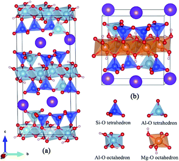 | ||
| Fig. 1 Optimized models of dioctahedral muscovite (a) and trioctahedral phlogopite (b) considering the arrangement of tetrahedral Al. | ||
During the simulations of the octahedral dissolution of mica in the fluorine-containing acid system, the surface models of octahedral layers were established basing on the structure of two types of mica as shown in Fig. 2. The surface charges resulted from the tetrahedral layer dissolves are balanced by hydrogen atoms. Meanwhile, a vacuum boundary of 20 Å was built to reduce the interactions between slabs. In order to maintain the influence of internal atoms on the surface structure, two rows of bottom atoms (including tetrahedral bottom oxygen atoms and tetrahedral center atoms) were fixed, and the other atoms were completely relaxed.
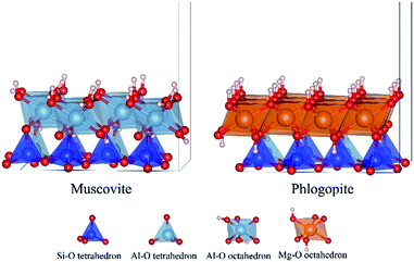 | ||
| Fig. 2 Structure models of the octahedral layers of dioctahedral muscovite and trioctahedral phlogopite. | ||
All calculations were performed with the Vienna Ab initio Simulation Package (VASP).17,18 The exchange-correlation energy was approximatively treated by the generalized gradient approximation (GGA) with the function of PBE-version.19,20 Meanwhile, the electron–ion interactions were described by the projector augmented wave (PAW) method.21,22 The plane-wave function was expanded with a kinetic energy cutoff value of 800 eV. Brillouin zone was sampled with a 4 × 4 × 2 Monkhorst–Pack k-point in the calculations of mica structure and V substitution. Considering the vacuum in octahedral layer models, Monkhorst–Pack k-point was built with a 3 × 3 × 1 mesh in the calculations of octahedral dissolution. Moreover, the dipole correction and van der Waals (VDW) force correction along the c-axis were considered in all surface calculations. All structures were relaxed using DFT methodology after a vanadium substitution has occurred. The total energy and residual forces were convergent until less than 10−5 eV and 0.05 eV Å−1, respectively.
The substitution energy (ES) of V in the different location of mica can be defined by the formula:
| ES = ET[α] − ET + Eα − EV | (1) |
The related potential energy (Ep,n) of each step of octahedral dissolution can be defined by the formula:
| Ep,n = ETn − ET0 + iEH2O − 2iEH − jEF | (2) |
Experimental materials and process
The samples of Vanadium-bearing black shale were obtained from Tongshan County, Hubei Province (Sample A) and Xiushui County, Jiangxi Province (Sample B), China. More than 80% of them were <0.074 mm. Their phase analysis was identified by X-ray diffraction (XRD, Empyrean, Panalytical, Netherlands) using Cu-Kα radiation. Their main chemical compositions were conducted with inductively coupled plasma-atomic emission spectroscopy (ICP-AES, Optima-4300DV, PerkinElmer, USA). Microscopic observation and elemental analysis were achieved by scanning electron microscopy (SEM, JSM-IT300, JEOL, Japan) equipped with an energy dispersive spectrometer (EDS, X-Act, Bruker, Oxford, Britain).Acid leaching experiments were conducted in a magnetic heating stirrer (DF-101S). The leaching conditions were carried out with the H2SO4 concentration of 25 vol%, the CaF2 dosage of 5 wt%, the leaching temperatures of 98 °C, and a constant liquid–solid ratio of 1.5 mL g−1. The residue and leachate were separated in the end. The chemical reagents used in this study were all of analytical grade. Ultrapure water was utilized throughout.
The leaching rate (η) is calculated by the formula:
 | (3) |
Results and discussion
Location of vanadium in mica
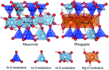
The location of V in mica determines the main attack target of cation and anion in the leaching process. Due to the poor crystal structure of mica in black shale, the accurate location of V in mica's lattice is difficult to be achieved. Quantum chemical simulation method was employed to investigate the optimal location of V in dioctahedral muscovite and trioctahedral phlogopite in this study. Considering the influence of the arrangement of Al in tetrahedral layers, Si–O tetrahedral sites could be divided into three non-degenerate types in both types of mica. The total five cases of V substitution were calculated in the mica structure: one Al–O tetrahedral site [AlIV], three Si–O tetrahedral sites [SiIV] and one Al–O octahedral site [AlVI] in muscovite or Mg–O octahedral site [MgVI] in phlogopite, which are displayed in Fig. 3.The changes of the bond lengths and angles of the local geometry as well as the values of substitution energy of each substitution site are displayed in Table 1. After the substitution of V, the lattices of muscovite expand, especially along the c axis. This deformation might result from the large vanadium atomic radius. The bond lengths are increased by 0.13–0.17 Å after the substitution of V for the M[SiIV] sites of muscovite. This extension of bond length is possibly owing to the larger ionic radius of V than Si. Consequentially, strong bonds in adjacent Si–O tetrahedron pull the bridge oxygen atoms out of the tetrahedral surface, and change the inter-tetrahedral bond angles about 2.2–8.3°. Similar to the M[AlIV] site substitution of muscovite, the bond lengths are increased by 0.12–0.14 Å, and the inter-tetrahedral bond angles change within 3.0–7.3°. For the M[AlVI] site substitution of muscovite, the resulting bond lengths are increased less than 0.11 Å, and the inter-octahedral angles change <1.1°. It means that V substitution in octahedron presents a smaller deformation than in tetrahedrons. Meanwhile, the V substitution of muscovite in octahedron obtains the lowest substitution energy in all configurations. So, V in muscovite most exist in the octahedron.
| Mica | Classify | Substituting sites | a (Å) | b (Å) | c (Å) | β (°) | Bond (Å) | Angle (°) | Es (eV) |
|---|---|---|---|---|---|---|---|---|---|
| a Considering the vanadium content and the atomic number of two kinds of mica, the supercell of 2 × 1 × 1 and 2 × 1 × 2 were carried out for muscovite and phlogopite respectively. | |||||||||
| Muscovite | No substitution | — | 10.58(×2) | 9.12 | 20.26 | 95.83 | — | — | 0 |
| Al–O octahedron | M[AlVI] | 10.54(×2) | 9.12 | 20.36 | 95.73 | <0.11 | 0.3–1.3 | −1.23 | |
| Al–O tetrahedron | M[AlIV] | 10.55(×2) | 9.13 | 20.38 | 95.73 | 0.12–0.14 | 3.0–7.3 | −0.35 | |
| Si–O tetrahedron | M[SiIV]1 | 10.57(×2) | 9.15 | 20.42 | 95.73 | 0.15–0.17 | 2.8–8.3 | −0.34 | |
| M[SiIV]2 | 10.57(×2) | 9.15 | 20.42 | 95.77 | 0.13–0.17 | 2.2–6.8 | −0.52 | ||
| M[SiIV]3 | 10.58(×2) | 9.14 | 20.42 | 95.74 | 0.16–0.17 | 3.9–6.0 | −0.43 | ||
| Phlogopite | No substitution | — | 10.78(×2) | 9.30 | 20.42(×2) | 101.91 | — | — | 0 |
| Mg–O octahedron | P[MgVI] | 10.74(×2) | 9.30 | 20.81(×2) | 101.41 | <0.02 | <0.7 | −2.31 | |
| Al–O tetrahedron | P[AlIV] | 10.76(×2) | 9.32 | 20.78(×2) | 101.48 | 0.13–0.14 | 1.2–6.1 | −0.57 | |
| Si–O tetrahedron | P[SiIV]1 | 10.77(×2) | 9.33 | 20.81(×2) | 101.48 | 0.15–0.18 | 3.2–4.7 | −0.51 | |
| P[SiIV]2 | 10.77(×2) | 9.33 | 20.81(×2) | 101.47 | 0.16–0.17 | 2.8–3.9 | −0.67 | ||
| P[SiIV]3 | 10.77(×2) | 9.33 | 20.81(×2) | 101.47 | 0.14–0.18 | 2.3–4.3 | −0.69 | ||
In the V substitution of phlogopite, the lattices similarly expand along the c axis. The changes of bond lengths and inter-tetrahedral bond angles of P[SiIV] sites are 0.14–0.18 Å and 2.3–4.7°, respectively. And the changes of bond lengths and inter-tetrahedral bond angles of P[AlIV] site are 0.13–0.14 Å and 1.2–6.1°, respectively. They are larger than the changes of P[MgVI] site, in which the bond lengths increase less than 0.02 Å and the inter-tetrahedral bond angles change no more than 0.7°. Similar to the substitution in muscovite, the octahedral substitution of V in phlogopite obtains the lowest substitution energy. So, V in phlogopite most exist in the octahedron. In all, V in both types of mica is most likely to locate in the octahedron. Further, the destruction of octahedral layer in mica represents the release of V. The structural difference of octahedral layer is the main reason for the difference of vanadium release between the two types of mica.
Essential difference of mica dissolution
The dissolution of the octahedron is the key step of V release because V is located in the mica octahedron. While, most of octahedral layer in mica is still Al–O octahedron or Mg–O octahedron. Therefore, the dissolution process of the octahedral layer which existing huge structural differences should be the focus of discussion. The octahedral models of two types of mica were established in Fig. 4 (M0 and P0). The differential essence of octahedral dissolution was revealed by simulating the reaction between octahedral interface and H+, F−. Considering the small ion radius of H+ and F−, the structural model of surface reaction was simplified with the dissociative H+ and F− ignoring the solvation effects on interface and ions.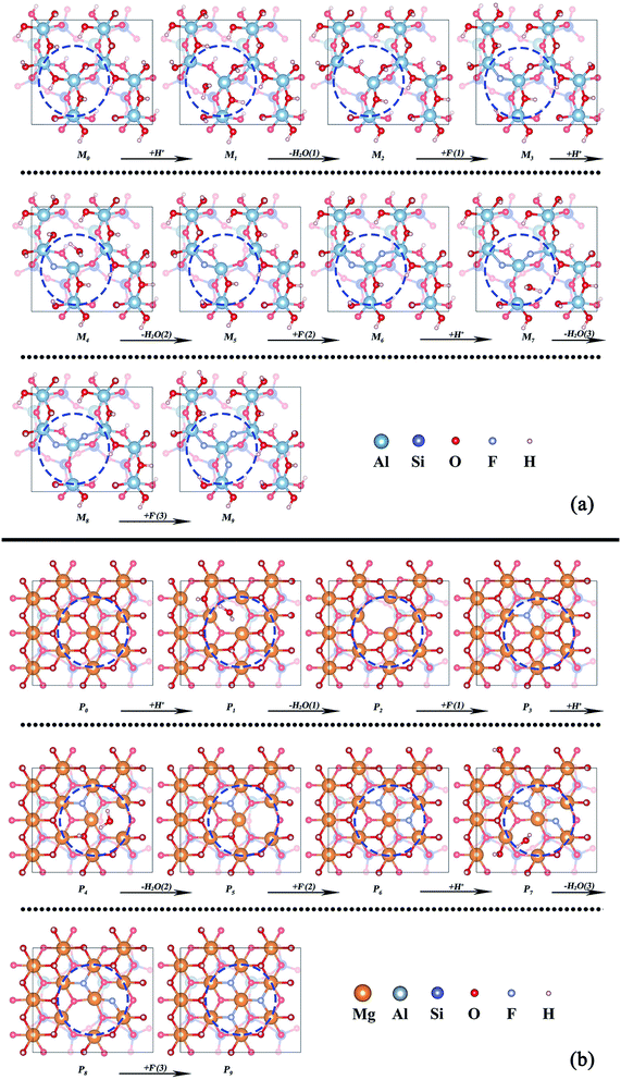 | ||
| Fig. 4 Removal of the structural oxygens on the octahedral surface of (a) muscovite (M0–M9) and (b) phlogopite (P0–P9). | ||
The dissolution process of octahedron can be separated into two parts: (1) removal of structural oxygens through the dehydroxylation reaction between interfacial hydroxyl and H+; (2) removal of the central atom of octahedron by binding with F−. In order to observe the atomic migration process of octahedrons, the three interfacial hydroxyl of the octahedron were artificially removed and F− were added to the defective octahedral surface one after another. The whole removal process of octahedron can be divided into 14 steps with 14 stable structures (M1–M14, P1–P14).
The removal processes of structural oxygens of the two types of mica are shown in Fig. 4a and b, respectively. Whether the dioctahedral muscovite or trioctahedral phlogopite, the coordination number of the central atom changed from 6 to 5 in the process of water removal, and then returned to 6 under the reaction of F−. The whole process has no significant influence on the adjacent octahedrons, it might because of the bondage of the underlying tetrahedral layer as well as the good plasticity of the octahedron itself.
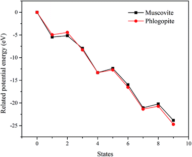
The related potential energies of the removal of structural oxygen atoms are displayed in Fig. 5, it is found that the formation of structural water makes the related potential energy of the system lower, while the removal of structural water requires a certain amount of energy input. However, F− makes up for the charge defect caused by the removal of structural oxygen atoms, which makes the related potential energy of the system decrease again. Except for the removal of the first structural oxygen atoms, the energies of the removal of the second and third structural oxygens on trioctahedral phlogopite are always lower than that of dioctahedral muscovite. It means that the structural oxygens of phlogopite is easier to be dissolved than that of muscovite.
The removal processes of the octahedral central atom of the two types of mica are shown in Fig. 6a and b, respectively. In muscovite, the addition of F− prompts the increase of the remaining Al–O bond of octahedron (M9 → M12) after the three surface structural oxygen atoms are replaced by three F−. It means that the center Al atom begins to move out of the octahedron. But the structural Al atom is completely detached from the octahedral surface and forms [AlF4]− until the seventh F− added (M13). Finally, [AlF5]2− is generated by the further coordination of F− (M14). This final state of Al3+ is consistent with the actual test result of Wang et al.23 In phlogopite, the center Mg atom is also pulled out of the octahedron by the addition of F− (P9 → P13). But the center Mg atom completely get away from the octahedral surface until the eighth F− added (P14).
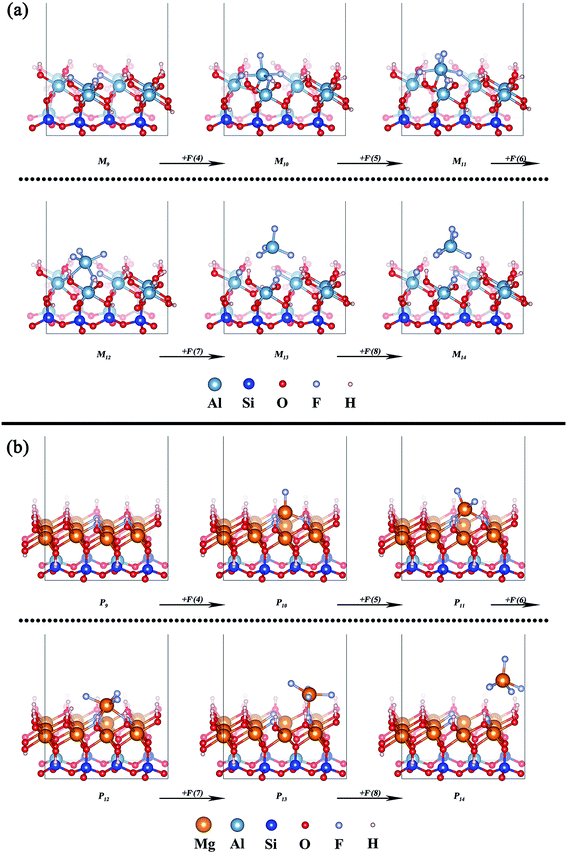 | ||
| Fig. 6 Removal of the octahedral central atom of (a) muscovite (M9–M14) and (b) phlogopite (P9–P14). | ||
The related potential energies of the removal of the octahedral central atom are displayed in Fig. 7. The removal of the octahedral central atom in phlogopite is always kept at lower related potential energy than that in muscovite, which indicates that the structural Mg of the trioctahedral phlogopite is more likely to be dissolved with the reaction of F− than the structural Al of the dioctahedral muscovite.
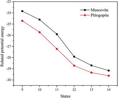 | ||
| Fig. 7 The related potential energies of the removal of the octahedral central atom in the two types of mica. | ||
Therefore, the octahedral layer of trioctahedral phlogopite can be collapsed more easily than that of dioctahedral muscovite. If there are more trioctahedral mica in black shale, it is more likely to achieve V dissolution, which can help to reduce acid consumption and shorten leaching time. On the contrary, if the content of dioctahedral type mica is higher, V in black shale is more difficult to release so that acid consumption and leaching time will increase.
Experimental comparison of two types of black shale
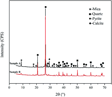
In order to verify the correctness of simulation analysis, two representative vanadium-bearing black shale were obtained from Tongshan County, Hubei Province (Sample A) and Xiushui County, Jiangxi Province (Sample B), China, respectively. XRD phase analysis (see Fig. 8) indicates that the same minerals of two types of black shale are mica, quartz and pyrite. Sample A contains calcite, while Sample B does not. The main chemical compositions of two samples were listed in Table 2.| Element | V2O5 | SiO2 | Al2O3 | Fe2O3 | CaO | MgO | BaO | K2O | Na2O | S | C (carbon) |
|---|---|---|---|---|---|---|---|---|---|---|---|
| Sample A | 0.74 | 49.28 | 8.91 | 4.99 | 6.26 | 2.18 | 1.36 | 3.02 | 0.12 | 3.86 | 13.44 |
| Sample B | 1.02 | 62.36 | 6.41 | 3.12 | 0.44 | 1.50 | 0.05 | 2.08 | 0.03 | 2.58 | 16.16 |
From the chemical phases of V in the two types of black shale (Table 3), the content of V is different in free oxide and organic matter between Sample A and Sample B. However, the content of V in silicate minerals is the highest and is almost the same in both samples.
| Chemical phase | Free oxide | Silicate minerals | Organic matter |
|---|---|---|---|
| Simple A | 10 | 87 | 3 |
| Simple B | 4 | 88 | 8 |
Furthermore, the V occurrence in these two types of black shale were detected by SEM-EDS, and the results of Sample A and Sample B are shown in Fig. 9. Fig. 9a indicates that the relevance of V, Mg, Al, K, Si and O is quite good. The high concentration of Al, low concentration of Mg, and atomic percentages of other elements at the scanning point on the mineral particle are enough to prove that V of Sample A exists in dioctahedral muscovite. Similarly, Fig. 9b also shows that the relevance of V, Mg, Al, K, Si and O is quite good. While, the low concentration of Al, high concentration of Mg, and atomic percentages of other elements at the scanning point on the mineral particle confirm that V of Sample B exists in trioctahedral phlogopite.
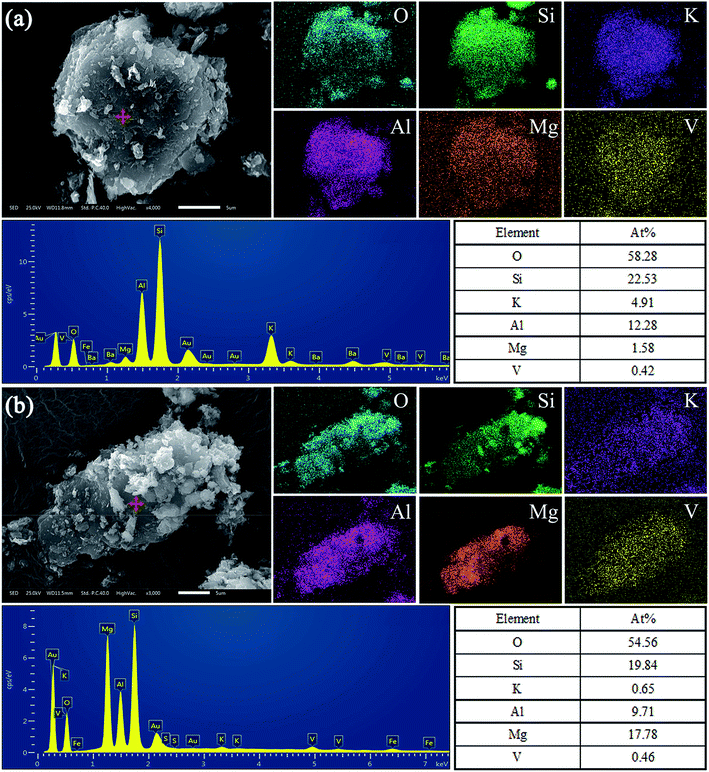 | ||
| Fig. 9 SEM-EDS analysis of main vanadium-bearing mineral particles of (a) Sample A and (b) Sample B. | ||
The variations of the leaching rate of V, Al and Mg of this two samples with the changes of leaching time have been compared. As shown in Fig. 10, the leaching rate of V of Sample B reached over 87% within 1 h, and still increased slowly with the extension of leaching time and finally reached 96%. While, the leaching rate of V of Sample A was only 45% after leaching 1 h. Although the leaching rate of V increased rapidly with the extension of time, it could only reach 73% in the end. All the time, the leaching rates of V of Sample B were always greater than that of Sample A. In the same way, the leaching rate of Al and Mg of Sample B were higher than that of Sample A. In other words, trioctahedral phlogopite in Sample B can be dissolved more rapidly than dioctahedral muscovite in Sample A. V in trioctahedral phlogopite is easier to be extracted than that in dioctahedral muscovite.
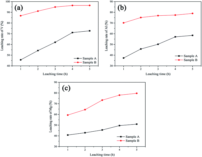 | ||
| Fig. 10 The comparison of leaching rate of V (a), Al (b) and Mg (c) between Sample A and Sample B under different leaching time. | ||
Conclusions
Different mica-type black shale present the apparent leachability differences caused by vanadium occupation and mica structure. Quantum chemical simulations infer that V in dioctahedral or trioctahedral mica, without exception, prefers to locate in mica octahedron as results of their minimum structural deformation and lowest substitution energy. During the octahedral dissolution process, the trioctahedral structure maintains low related potential energy, which is easier to react with H+ and F− than the dioctahedral structure for achieving the structural collapse. Comparing the leachability of representative vanadium-bearing black shale from different regions, trioctahedral mica-type black shale obtained the higher leaching rate of V than dioctahedral mica-type black shale. With the content of trioctahedral mica in black shale increasing, V can be relatively easy to release in the short time under low-acidity leaching.Conflicts of interest
The authors declare that they have no conflict of interest.Acknowledgements
This work was supported by the National Key R&D Program of China (No. 2018YFC1900505) and National Natural Science Foundation of China (No. 51804226).References
- S. Dai, X. Zheng, X. Wang, R. B. Finkelman, Y. Jiang, D. Ren, X. Yan and Y. Zhou, Int. Geol. Rev., 2017, 60, 736–753 CrossRef.
- Y. Zhang, S. Bao, T. Liu, T. Chen and J. Huang, Hydrometallurgy, 2011, 109, 116–124 CrossRef CAS.
- Y. Zhang, Vanadium extraction from stone coal (in Chinese), Science Press, Beijing, 2014 Search PubMed.
- N. Xue, Y. Zhang, T. Liu, J. Huang and Q. Zheng, J. Cleaner Prod., 2017, 149, 989–998 CrossRef CAS.
- B. Yan, D. Wang, L. Wu and Y. Dong, Miner. Eng., 2018, 125, 231–238 CrossRef CAS.
- Z. L. Cai, Y. M. Zhang, T. Liu and J. Huang, JOM, 2015, 67, 2629–2634 CrossRef CAS.
- J. K. Pearce, G. K. W. Dawson, A. C. K. Law, D. Biddle and S. D. Golding, Appl. Geochem., 2016, 72, 59–76 CrossRef CAS.
- A. Steudel, L. F. Batenburg, H. R. Fischer, P. G. Weidler and K. Emmerich, Appl. Clay Sci., 2009, 44, 95–104 CrossRef CAS.
- E. H. Oelkers, J. Schott, J.-M. Gauthier and T. Herrero-Roncal, Geochim. Cosmochim. Acta, 2008, 72, 4948–4961 CrossRef CAS.
- D. Tunega and H. Lischka, Phys. Chem. Miner., 2003, 30, 517–522 CrossRef CAS.
- S. M. Opalka and T. Zhu, Microporous Mesoporous Mater., 2016, 222, 256–270 CrossRef CAS.
- Y. Li, X. Cheng and Y. Zhang, J. Electrochem. Soc., 2012, 159, A69–A74 CrossRef CAS.
- P. Yang, B. Tai, W. Wu, J. M. Zhang, F. Wang, S. Guan, W. Guo, Y. Lu and S. A. Yang, Phys. Chem. Chem. Phys., 2017, 19, 16189–16197 RSC.
- Q. Zheng, Y. Zhang, T. Liu, J. Huang, N. Xue and Q. Shi, Minerals, 2017, 7, 32 CrossRef.
- M. Catti, G. Ferraris, S. Hull and A. Pavese, Eur. J. Mineral., 1994, 6, 171–178 CrossRef CAS.
- D. R. Collins and C. R. A. Catlow, Am. Mineral., 1992, 77, 1172–1181 CAS.
- G. Kresse and J. Furthmüller, Comput. Mater. Sci., 1996, 6, 15–50 CrossRef CAS.
- G. Kresse and J. Hafner, Phys. Rev. B: Condens. Matter Mater. Phys., 1993, 48, 13115–13118 CrossRef CAS PubMed.
- J. P. Perdew, J. A. Chevary, S. H. Vosko, K. A. Jackson, M. R. Pederson, D. J. Singh and C. Fiolhais, Phys. Rev. B: Condens. Matter Mater. Phys., 1992, 46, 6671–6687 CrossRef CAS PubMed.
- J. P. Perdew, K. Burke and Y. Wang, Phys. Rev. B: Condens. Matter Mater. Phys., 1996, 54, 16533–16539 CrossRef CAS PubMed.
- P. E. Blöchl, Phys. Rev. B: Condens. Matter Mater. Phys., 1994, 50, 17953–17979 CrossRef PubMed.
- G. Kresse and D. Joubert, Phys. Rev. B: Condens. Matter Mater. Phys., 1999, 59, 1758–1775 CrossRef CAS.
- F. Wang, Y. Zhang, T. Liu, J. Huang, J. Zhao, G. Zhang and J. Liu, Int. J. Miner. Process., 2015, 145, 87–93 CrossRef CAS.
| This journal is © The Royal Society of Chemistry 2019 |

