 Open Access Article
Synthesis of core–shell magnetic titanate nanofibers composite for the efficient removal of Sr(II)†
Rong Yi*a,
Gang Yeb and
Jing Chen*b
aSchool of Material Science and Engineering, Sun Yat-Sen University, Guangzhou 510275, China. E-mail: yirong280@163.com
bInstitute of Nuclear and New Energy Technology (INET), Tsinghua University, Beijing 100084, China. E-mail: jingxia@tsinghua.edu.cn
First published on 30th August 2019
Abstract
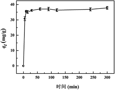
We report a facile approach for the fabrication of Fe3O4@titanate fibers magnetic composite through a hydrothermal method and sol–gel process. The structure and morphology were characterized by X-ray diffraction (XRD), transmission electron microsphere (TEM), scanning electron microscope (SEM) and energy-dispersive X-ray analysis (EDX). Owing to the high ion exchange capacity of the functional titanate layer, the obtained core–shell structured magnetic microspheres exhibited high removal efficiency towards strontium from wastewater. The effects of contact time and Sr(II) concentration on the uptake amount of strontium were systematically investigated. The results indicated that the adsorption equilibrium can be reached within 30 min, and the maximum exchange capacity was approximately 37.1 mg g−1. Moreover, the captured Sr(II) can be eluted using 5 wt% of EDTA(Na), which contributed to the reduction of waste volume. Based on the experimental results of ion exchange process and X-ray photoelectron spectroscopy (XPS), a possible adsorption mechanism was proposed. This work provided a facile approach to synthesize magnetic functional nanocomposites for wastewater treatment.
Introduction
Environmental contamination with harmful fission products (FPs), which are generated during the operation of nuclear facilities, has aroused world-wide concern after the nuclear accident at Fukushima, Japan.1,2 The leak of radionuclides may give rise to a serious threat to human health. For example, 90Sr is one of the typical FPs and is found in operational waste from reactors and reprocessing plants.3 It was possesses a long half-life (T1/2 = 28.5 years), high radioactivity and is a biological hazard. Moreover, 90Sr can substitute for calcium in bones, leading to increased risk of leukemia and other diseases.4In order to address this issue, many techniques have been developed to remove radionuclides from radioactive streams and their subsequent disposal, including membrane distillation,5,6 reverse osmosis7,8 and solvent extraction.9 However, these methods currently deployed to manage radioactive waste can be complex and extremely costly.10 Inorganic cation exchangers, especially synthetic inorganic cation exchanger materials, such as layered zirconium phosphates synthetic micas,11,12 titanium molybdophosphate13 and layered titanate nanofibers,14–16 are recognized as a promising candidates for the removal of radioactive cations owing to their large ion exchange capacity, high selectivity, excellent irradiation and chemical stability. The radioactive ions can be captured from wastewater through preferentially exchanging with sodium ions or proton in the synthetic materials. Recently, a novel synthetic inorganic exchange, trititanate nanofibers (with a chemical formula Na2Ti3O7), has been shown to exhibit high removal efficiency towards Sr(II).17,18 Furthermore, its interlayer containing sodium cations are replaced by strontium along with a structural collapse, avoiding the trapped radioactive ions releasing to water again.
However, nanoscale of this adsorbent made it difficult for solid–liquid separation, especially under radioactive operating condition. Even if they were employed in column separation to avoid this issue, under-size and irregular particles lead to a surge of column pressure, and more importantly, inadequate strength and unsuitable mechanical properties rendered them unsuitable for industrial application. Therefore, a support material was needed to be introduced to overcome these shortcomings.
In recent years, many researchers focus on magnetic nanocomposite because of their rapid separation performance under external magnetic field. Decorating magnetic particle with specific extractant or ion exchange opened a new perspective for the separation of radionuclides, which combined the high adsorption capacity with advantage of magnetic separation.19,20 Böhmer et al. functionalized magnetic silica particles with tetra-CMPO-calix[4]arenes to magnetically assisted removal of lanthanides and actinides,21,22 which showed high adsorption efficiency towards Eu(III), Am(III), Ce(III). Yang et al. prepared magnetic Prussian blue/graphene oxide nanocomposites for the removal of radioactive cesium in water and its maximum adsorption capacity was up to 55.56 mg g−1.23 Song et al. fabricated a multi-shelled magnetic Fe3O4@MnOx hollow composite and the adsorbent displayed considerable sorption capacities towards uranium (U(VI)) and europium (Eu(III)). According to their spectroscopic studies, U(VI) was proved to be adsorbed on the MnIII–O–H site while Eu(III) shows higher affinity to the MnIV–O–H site.24
Therefore, from the perspective of practical application, the titanate fiber incorporated with magnetic particles will provide a promising technology for the removal of radioactive strontium. Until now, several studies have reported the fabrication strategy of magnetic titanate nanocomposites. Liu et al. utilized van der Waals interactions to synthesis a novel and facile acid-induced self-assembly process to tightly anchor Fe3O4 NPs onto the surfaces of titanate nanostructures.25 Niu et al. prepared magnetic titanate nanotube through a co-precipitation process based on the exchange of protons with Fe2+/Fe3+ ions, followed by functionalized with C18 groups for the efficient extraction of phthalate esters.26 However, the Fe3O4 particle in their synthetic nanocomposite was naked, which were susceptible to air oxidation. Therefore, a protective layer was needed to be introduced onto the surface of Fe3O4 particle. Besides, to our knowledge, employing magnetic titanate fibers with core–shell structure for the removal of strontium (Sr(II)) have never been reported.
Herein, a new kind of core–shell structured magnetic microspheres decorated with titanate fibers was prepared for the removal of strontium, which was obtained from Fe3O4@SiO2@TiO2 under hydrothermal treatment at 160 °C in 10 M NaOH solution. The synthetic procedure was optimized and the morphology of the magnetic microspheres was detailed. In this process we found that the introduction of silica layer will benefit to the immobilization of titanate fibers. Adsorption kinetics and isotherms of magnetic microspheres towards Sr(II) were investigated through batch experiments. In addition, a possible adsorption mechanism was raised based on the variation of ions during adsorbing process and the X-ray photoelectron spectroscopy (XPS) analyses.
Experimental
Chemicals
Ferric chloride hexahydrate (FeCl3·6H2O), anhydrous sodium acetate, ethylene glycol (EG), tetraethyl orthosilicate (TEOS) were purchased from Sigma-Aldrich. Tetrabutyl orthotitanate (TBOT) and hydroxypropyl cellulose (HPC) were supplied by J&K. All chemicals were analytical grade used without further purification. Deionized water was obtained from a Milli-Q water purification system.Synthesis of Fe3O4@SiO2@TiO2 microspheres
The Fe3O4@SiO2@TiO2 microspheres were prepared as described in our previous work.27 First, the magnetic core Fe3O4 was synthesized through a solvothermal method.28 Briefly, 2.70 g of FeCl3·6H2O and 7.2 g of sodium acetate were dissolved in 100 mL ethylene glycol under magnetic stirring to obtain a homogeneous yellow solution. The mixed solution was then transferred into a Teflon-lined stainless-steel autoclave and heated at 200 °C for 8 h. Finally, the products was washed with ethanol and deionized water and dried in vacuum at 60 °C for 12 h.To obtain Fe3O4@SiO2@TiO2 microspheres, the magnetite particles were coated with a thin layer of silica and titania via sol–gel approach, respectively. Typically, 0.5 g Fe3O4 particles was treated with 0.1 mol L−1 HCl aqueous solution by ultrasonication and washed with deionized water, followed by dispersion in a mixture of absolute ethanol (200 mL), deionized water (50 mL) and concentrated ammonia aqueous solution (2.5 mL, 28 wt%). Tetraethyl orthosilicate (TEOS, 0.5 mL) was added to the above solution drop by drop. After stirring at room temperature for 6 h, the Fe3O4@SiO2 microspheres were separated by using a magnet, washed with ethanol and deionized water, and then mixed with deionized (3 mL), HPC (1.25 g) and absolute ethanol (400 mL). 5 mL of TBOT was added dropwise under vigorous mechanical stirring and the mixed solution was heated to 85 °C for 2.5 h. The product was washed with ethanol for three times and dried in vacuum at 60 °C for 8 h.
Preparation of Fe3O4@titanate nanofibers composite
Typically, Fe3O4@SiO2@TiO2 particles (0.2 g) was added to a solution of NaOH (25 mL, 10 M) followed by ultrasound for 15 min. The mixture was then placed into a Teflon-lined autoclave, sealed and hydrothermally treated at 160 °C for 48 h. The product was recovered with the help of magnet and washed with deionized water until a pH value was approximate 8. After an alcohol washing step, the sample was dried at 60 °C for 8 h in vacuum.Ion-exchange experiments
The ion-exchange behavior of Sr(II) onto the magnetic titanate nanocomposites was studied by batch experiments. 10 mg of microspheres was added into 4 mL of SrCl2 solution with a pH value of 6.5. The adsorption kinetic was investigated via altering contact time from 5 min to 240 min and the adsorption isotherm was determined by varying the initial strontium concentration between 0.05–0.5 g L−1. After being shaking for specific contact time in 25 °C constant temperature bath oscillator, the solid phase was separated by using an NdFeB magnet and the aqueous solution was filtered with syringe-type filters. The concentration of strontium in the supernatant was analyzed by atomic absorption spectroscopy (AAS). The distribution coefficient (Kd) and adsorption capacity qt were calculated by following equations:
 | (1) |
 | (2) |
Characterizations
X-ray diffraction (XRD) patterns of powder samples were recorded on a Bruker D8 Advance-X-ray diffractometer with monochromatized CuKα radiation (λ = 1.5418 Å). The size and morphology of magnetic microspheres was observed using ZEISS 1530 scanning electron microscope (SEM) and JEM 2011 transmission electron microscopes (TEM). Atomic Absorption Spectroscopy (AAS) was used to determine the concentration of metal ions. X-ray photoelectron spectroscopy (XPS) measurement was carried out on an Axis Ultra (Kratos Analytical Ltd) imaging photoelectron spectrometer using a monochromatized aluminum Kα anode, and the C 1s peak at 284.8 eV was taken as an internal standard.Results and discussion
Characterization of materials
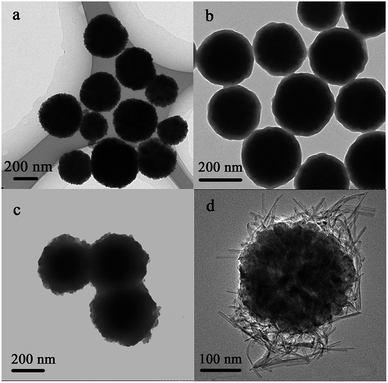
Fig. 1 shows the morphology of the Fe3O4, Fe3O4@SiO2, Fe3O4@SiO2@TiO2 and Fe3O4@titanate. The magnetic core Fe3O4 particles (Fig. 1a) have a mean diameter of approximate 300 nm. After coating with silica via the typical Stöber method, an evident core–shell structure can be observed from Fig. 1b and the thickness of silica layer was about 20 nm. Since the titanate fibers can be obtained from the reaction between TiO2 polymorphs and concentrated NaOH solution at lower hydrothermal temperatures,29 a layer of titania was introduced as reagent to the Fe3O4@SiO2 microspheres using sol–gel approach, resulting in an obvious thickness increase of shell layer (Fig. 1c). Finally, the resultant outer layer TiO2 reacted with 10 M NaOH solution at hydrothermal under 160 °C. The obtained titanate fibers was deposited on the magnetic microspheres, forming Fe3O4/titanate nanofibers magnetic composite (Fig. 1d). In order to identify the pore structure and porosity of Fe3O4/titanate fibers, nitrogen adsorption–desorption characterization was conducted and the results were given in Fig. S1 and Table S1.† Due to the high proportion of magnetic core, the Fe3O4/titanate fibers showed a comparatively low specific surface area of 56.7 m2 g−1 and pore volume of 0.2 cm3 g−1. But its large average pore width contributed to mass transfer of adsorption process.In synthetic process, the SiO2 layer was destroyed because of its poor alkali resistance. However, element Si was still detected in the final composite through EDS study (Fig. S2†). In order to check its role in the deposition process of titanate fibers, a contrast trial was conducted without the silicon coating step, only a layer of TiO2 was deposited onto the outside surface of Fe3O4 particle before hydrothermal treatment. Its image was shown in Fig. S3a,† which showed that the titanate nanofibers had not merged with magnetic precursor and were scattered independently. It is concluded that the SiO2 layer contributed to the immobilization of titanate nanofibers.
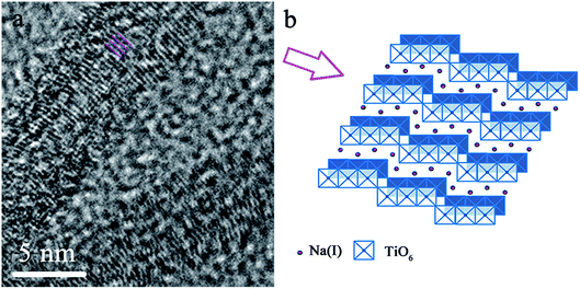
To further identify the structure of deposited titanate nanofiber, high resolution transmission electron microscopy (HRTEM) was utilized and its image was displayed in Fig. 2. It can be seen that the nanofiber possessed quite obvious layered structure, in which TiO6-octahedra were the basic structure unit, each TiO6 octahedron shared edges with other octahedra to form zigzag layer.18 The exchangeable Na(I) ions were distributed in interlayers and can be substituted with other cations during ion exchange process.
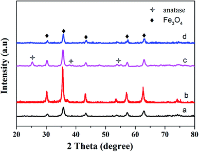
The structure change during synthetic process was confirmed by XRD studies. Fig. 3a shows the XRD pattern of the Fe3O4@SiO2@TiO2 particles. All diffraction peaks only could be indexed to the magnetite phase of Fe3O4 (JCPDS 19-629), indicating that the SiO2 and TiO2 were both amorphous. However, after reacting with 10 M NaOH at 160 °C hydrothermal condition, the XRD pattern of final product, as shown in Fig. 3b, only matched well with the magnetite. No characteristic peaks of other materials were detected, which may be due to the low crystallinity of obtained titanate fibers. In order to improve this situation, the precursor, Fe3O4@SiO2@TiO2 particles, were calcinated at 500 °C for 2 h. The outer layer amorphous TiO2 transformed to the anatase phase, which can be confirmed by the appearance of new peaks in Fig. 3c. All of them can be indexed to the anatase phase of TiO2 (JCPDS 21-1272).30 But all the diffraction peaks of anatase disappeared after treated with 10 M NaOH in a Teflon-lined autoclave at 160 °C. This result implied that enhancing the crystallinity of reagent TiO2 did not contribute to the improvement of crystallinity in final product.
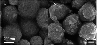
The surface morphology evolution after calcination treatment of precursor was revealed by SEM. The micrograph of the Fe3O4/titanate obtained from uncalcined Fe3O4@SiO2@TiO2 particles was provided in Fig. 4a. It can be seen that plenty of titanate fibers covered the surface of final product. On the other hand, the Fe3O4/titanate prepared from Fe3O4@SiO2@TiO2 particles after calcination at 500 °C were nanosheets aggregates of titanate, as is evident from the image shown in Fig. 4b. The composition of Fe3O4/titanate nanofibers was verified by EDS (Fig. S2 and Table S2†), which exhibited the existence of Na and Ti with a molar radio close to 2![[thin space (1/6-em)]](https://www.rsc.org/images/entities/char_2009.gif) :
:![[thin space (1/6-em)]](https://www.rsc.org/images/entities/char_2009.gif) 3. This was consistent with Na2Ti3O7.
3. This was consistent with Na2Ti3O7.
Adsorption behavior study
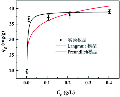
 | (3) |
| qe = KFCe1/n | (4) |
As shown in Fig. 6, the Langmuir adsorption isotherm model fit well with experiment data better, suggesting that the adsorbent surface was heterogeneous. The Langmuir isotherm constants and their correction coefficients were listed in Table S3† and the maximum adsorption capacity was calculated to be 39.08 mg g−1.
Comparison of various magnetic adsorbents
A comparison between Fe3O4/titanate fibers and some other reported magnetic composites for Sr(II) adsorption was conducted and the results were presented in Table 1.32–41 It can be seen that the magnetic titanate nanofibers exhibits excellent adsorption ability among magnetic composite used for Sr(II) removal. Although some magnetic adsorbents, such as magnetic polyaniline/graphene oxide, magnetic Sr(II)-imprinted polymer, shows high adsorption capacity towards Sr(II) as well, the time for establishing adsorption equilibrium is more than 2 h. By contrast, the magnetic titanate nanofibers is endowed with rapid Sr(II) uptake rate and the adsorption equilibrium can be reach within 30 min.| Adsorbent | Equilibrium time | Adsorption capacity (mg g−1) | Ref. |
|---|---|---|---|
| Multiwall carbon nanotube/iron oxide magnetic | 40 min | 9.18 | 32 |
| Graphene oxide-magnetite | 5 h | 14.1 | 33 |
| Magnetic polyaniline/graphene oxide | 12 h | 37.17 | 34 |
| Magnetic Fe3O4 particles modified sawdust | 30 min | 12.59 | 35 |
| Bis(trimethoxysilypropyl) functionalized magnetic particles | 90 min | 3.15 | 36 |
| Magnetic clinoptilolite/CoFe2O4 composites | 1200 min | 20.58 | 37 |
| Synthesized magnetic chitosan beads | 6 h | 11.58 | 38 |
| Magnetic Sr(II)-imprinted polymer | 120 min | 54.49 | 39 |
| Alginat/Fe3O4 composite | 6 h | 12.5 | 40 |
| Magnetic microspheres impregated with crown ether | 10 h | 9.05 | 41 |
| Magnetic titanate nanofibers | 30 min | 37.1 | This work |
Elution and reusability
90Sr is a common β radioactive source. Regeneration of adsorbed Sr(II) will yield some economical benefit. Moreover, it can contribute to reduction and degradation of radioactive waste. Therefore, it necessary to investigate the elution of adsorbed Sr(II) by using various eluent and the results is shown in Table S4.† It could be clearly observed that the captured Sr(II) can be eluted by using 5 wt% of EDTA(Na) and desorption rate is up to 92.2%. However, when the composite is reused for Sr(II) removal, the adsorption ability experienced a significant decline. Similar phenomenon can be found in many reported synthetic ion exchangers for Sr(II) uptake, resulted from the collapses of interlayered structure.11,14,42 As for titanate nanofibers, when part of the Na(I) ions is replaced by Sr(II), a significant reduction of the interlayer spacing (d100) can be observed and the (003) planes is found to be substantial deformation because of the strong interaction between the (003) planes and the Sr(II) ions.18 Owing to the strong affinity between the Sr(II) ions and the negatively charged layers in titanate nanofiber, the magnetic composite was endowed with high selectively toward Sr(II) and it was difficult for the absorbed Sr(II) to release into the environment again.Adsorption mechanism
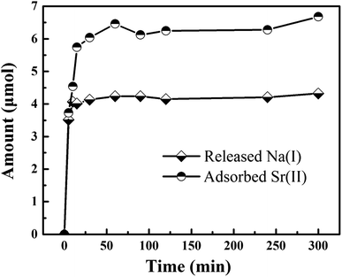
Based on the previous study, the adsorption of titanate toward ions was the process of Na(I) replacement by Sr(II), which existed in interlayers of adsorbent. Therefore, we supposed the Sr(II) are entirely exchanged with Na(I) during the adsorption of Fe3O4/titanate fibers towards Sr(II). The variation of ions with the increasing of contact time, including released Na(I) and adsorbed Sr(II), can be monitored. The changing amount versus time were plotted in Fig. 7. It is noted that sodium ions appear in the solution after adsorption and the concentration increases with the increase of adsorbed strontium ions. However, the radio between the molar amount of released Na(I) and the amount of adsorbed Sr(II) was calculated to be about 1.7, not up to 2, indicating other components were likely to be involved in the Sr(II) adsorption.In order to further confirm the adsorption mechanism, the XPS of the samples before (MT3) and after Sr(II) adsorption (MT3-Sr) were measured. To further understand the electronic states of the elements and investigate the interaction between the functional groups of Fe3O4/titanate fibers and Sr(II), high resolution spectra of Na 1s, Sr 3d, Fe 2p, Ti 2p and O 1s were recorded and the results were presented in Fig. 8. Direct evidence for an ion exchange process between Sr(II) and Na(I) ions which existed in the interlayers of the titanate were found in Fig. 8a and b. After Sr2+ adsorption, the peak at 1071.55 eV (Fig. 8a) assigned to the Na 1s peak disappeared, indicating that Na(I) ions were almost completely exchanged. Meanwhile, a double characteristic peak of Sr(II) 3d at 133.73 and 135.52 eV (Fig. 8b) appear in the spectrum of adsorbed sample, which were contribute to the Sr 3d5/2 and Sr 3d3/2, respectively. In the Fe 2p spectrum, a slight shift of Fe 2p peaks at 710.50 and 724.40 eV were observed, revealing that Fe3O4 was involved in the adsorption of Sr(II), which accounted for the phenomenon that the radio between the molar amount of released Na(I) and the amount of adsorbed Sr(II) was less than 2. Besides, the Ti 2p peaks (Fig. 8d) at 458.45 and 464.25 eV are shifted to higher binding energies on account of the interaction between TiO6 octahedron and Sr(II). From the O 1s higher-resolution deconvolution spectra of Fig. S4,† three different peaks centered at 529.97, 531.30 and 532.66 eV were observed. The peak at 529.97 eV was attributed to O 1s of TiO6 or FeO6 octahedra and was shifted to a higher binding energy after Sr(II) adsorption (Fig. S5†).
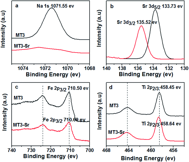 | ||
| Fig. 8 XPS high resolution spectra of (a) Na 1s, (b) Sr 3d (c) Fe 2p and (d) Ti 2p before and after Sr(II) adsorption; Sr 3d spectrum of the Sr(II)-adsorbed sample. | ||
Conclusions
In this paper, a novel core–shell structured magnetic nanocomposite sorbent Fe3O4@titanate fiber was prepared through hydrothermal and sol–gel process. The composite showed high exchangeable capacity towards strontium due to the introduction of sodium titanate. Batch experiments showed that the exchange balance can be established within 30 min and adsorption isotherm fits well with the Langmuir isotherm model. The maximum exchange capacity was approximately 37.1 mg g−1. Through monitoring the variation of ions with the increasing of contact time and employing XPS analysis, a possible adsorption mechanism was raised that naked Fe3O4 particle and the titanate fiber contribute to the removal of Sr(II). This novel magnetic composite shows great potential for the strontium removal from wastewater.Conflicts of interest
There are no conflicts of interest to declare.Acknowledgements
The study was supported by the National Natural Science Foundation of China under Project 51425403 and 51473087.References
- R. Yi, G. Ye, F. C. Wu, M. F. Wen, X. G. Feng and J. Chen, RSC Adv., 2014, 4, 37600–37608 RSC.
- M. Ishizaki, S. Akiba, A. Ohtani, Y. Hoshi, K. Ono, M. Matsuba, T. Togashi, K. Kananizuka, M. Sakamoto, A. Takahashi, T. Kawamoto, H. Tanaka, M. Watanabe, M. Arisaka, T. Nankawa and M. Kurihara, Dalton Trans., 2013, 42, 16049–16055 RSC.
- E. Wieland, J. Tits, D. Kunz and R. Dähn, Environ. Sci. Technol., 2008, 42, 403–409 CrossRef CAS PubMed.
- S. Langley, A. G. Gault, A. Ibrahim, Y. Takahashi, R. Renaud, D. Fortin, I. D. Clark and F. G. Ferris, Environ. Sci. Technol., 2009, 43, 1008–1014 CrossRef CAS PubMed.
- H. Liu and J. Wang, J. Hazard. Mater., 2013, 261, 307–315 CrossRef CAS PubMed.
- F. Jia, Y. Yin and J. Wang, Prog. Nucl. Energy, 2018, 103, 20–27 CrossRef CAS.
- K. P. Lee, T. C. Arnot and D. Mattia, J. Membr. Sci., 2011, 370, 1–22 CrossRef CAS.
- S. Lee, Y. Kim, J. Park, H. K. Shon and S. Hong, J. Membr. Sci., 2018, 556, 238–247 CrossRef CAS.
- T. J. Stockmann, Y. Lu, J. Zhang, H. H. Girault and Z. Ding, Chem.–Eur. J., 2011, 17, 13206–13216 CrossRef CAS PubMed.
- S. Sarina, A. Bo, D. Liu, H. Liu, D. Yang, C. Zhou, N. Maes, S. Komarneni and H. Zhu, Chem. Mater., 2014, 26, 4788–4795 CrossRef CAS.
- W. J. Paulus, S. Komarneni and R. Roy, Nature, 1992, 357, 571–573 CrossRef CAS.
- T. Kodama, Y. Harada, M. Ueda, K. Shimizu, K. Shuto and S. Komarneni, Langmuir, 2001, 17, 4881–4886 CrossRef CAS.
- R. Yavari, S. J. Ahmadi, Y. D. Huang, A. R. Khanchi, G. Bagheri and J. M. He, Talanta, 2009, 77, 1179–1184 CrossRef CAS PubMed.
- D. Yang, Z. Zheng, H. Liu, H. Zhu, X. Ke, Y. Xu, D. Wu and Y. Sun, J. Phys. Chem. C, 2008, 112, 16275–16280 CrossRef CAS.
- D. Yang, H. Liu, L. Liu, S. Sarina, Z. Zheng and H. Zhu, Nanoscale, 5, 11011–11018 RSC.
- D. Yang, Z. Zheng, Y. Yuan, H. Liu, E. R. Waclawik, X. Ke, M. Xie and H. Zhu, Phys. Chem. Chem. Phys., 2010, 12, 1271–1277 RSC.
- D. J. Yang, Z. F. Zheng, H. Y. Zhu, H. W. Liu and X. P. Gao, Adv. Mater., 2008, 20, 2777–2781 CrossRef CAS PubMed.
- D. Yang, H. Liu, Z. Zheng, S. Sarina and H. Zhu, Nanoscale, 2013, 5, 2232–2242 RSC.
- M. Liu, C. Chen, T. Wen and X. Wang, Dalton Trans., 2014, 43, 7050–7056 RSC.
- L. Tan, X. Zhang, Q. Liu, J. Wang, Y. Sun, X. Jing, J. Liu, D. Song and L. Liu, Dalton Trans., 2015, 44, 6909–6917 RSC.
- V. Böhmer, J. F. Dozol, C. Gruttner, K. Liger, S. E. Matthews, S. Rudershausen, M. Saadioui and P. S. Wang, Org. Biomol. Chem., 2004, 2, 2327–2334 RSC.
- S. E. Matthews, P. Parzuchowski, A. Garcia-Carrera, C. Gruttner, J. F. Dozol and V. Böhmer, Chem. Commun., 2001, 417–418 RSC.
- H. Yang, L. Sun, J. Zhai, H. Li, Y. Zhao and H. Yu, J. Mater. Chem. A, 2014, 2, 326–332 RSC.
- S. Song, S. Zhang, S. Huang, R. Zhang, L. Yin, Y. Hu, T. Wen, L. Zhuang, B. Hu and X. Wang, Chem. Eng. J., 2019, 355, 697–709 CrossRef CAS.
- F. Liu, Y. Jin, H. Liao, L. Cai, M. Tong and Y. Hou, J. Mater. Chem. A, 2013, 1, 805–813 RSC.
- H. Niu, S. Zhang, X. Zhang and Y. Cai, ACS Appl. Mater. Interfaces, 2010, 2, 1157–1163 CrossRef CAS PubMed.
- R. Yi, G. Ye, F. Wu, M. Wen, X. Feng and J. Chen, RSC Adv., 2014, 4, 37600–37608 RSC.
- Y. Deng, D. Qi, C. Deng, X. Zhang and D. Zhao, J. Am. Chem. Soc., 2007, 130, 28–29 CrossRef PubMed.
- H. Y. Zhu, Y. Lan, X. P. Gao, S. P. Ringer, Z. F. Zheng, D. Y. Song and J. C. Zhao, J. Am. Chem. Soc., 2005, 127, 6730–6736 CrossRef CAS PubMed.
- M. Ye, Q. Zhang, Y. Hu, J. Ge, Z. Lu, L. He, Z. Chen and Y. Yin, Chem.–Eur. J., 2010, 16, 6243–6250 CrossRef CAS PubMed.
- C. Cao, F. Wei, J. Qu and W. Song, Chem.–Eur. J., 2013, 19, 1558–1562 CrossRef CAS PubMed.
- C. Chen, J. Hu, D. Shao, J. Li and X. Wang, J. Hazard. Mater., 2009, 164, 923–928 CrossRef CAS PubMed.
- A. Tayyebi, M. Outokesh, S. Moradi and A. Doram, Appl. Surf. Sci., 2015, 353, 350–362 CrossRef CAS.
- B. Hu, M. Qiu, Q. Hu, Y. Sun, G. Sheng, J. Hu and J. Ma, ACS Sustainable Chem. Eng., 2017, 5, 6924–6931 CrossRef CAS.
- Z. Cheng, Z. Gao, W. Ma, Q. Sun, B. Wang and X. Wang, Chem. Eng. J., 2012, 209, 451–457 CrossRef CAS.
- X. Ye, T. Liu, Q. Li, H. Liu and Z. Wu, Colloids Surf., A, 2008, 330, 21–27 CrossRef CAS.
- Y. Huang, W. Wang, Q. Feng and F. Dong, J. Saudi Chem. Soc., 2017, 21, 58–66 CrossRef CAS.
- Y. Chen and J. Wang, Nucl. Eng. Des., 2012, 242, 445–451 CrossRef CAS.
- L. Yan, C. Rui, D. Yuan, Z. Liu, M. Meng, W. Yun, J. Han, X. Meng, F. Liu and Z. Hu, Colloid Polym. Sci., 2015, 293, 109–123 CrossRef.
- H. Hong, H. S. Jeong, B. Kim, J. Hong, I. Park, T. Ryu, K. Chung, H. Kim and J. Ryu, Chemosphere, 2016, 165, 231–238 CrossRef CAS PubMed.
- R. Yi, G. Ye, F. Wu, D. Lv and J. Chen, J. Radioanal. Nucl. Chem., 2016, 308, 599–608 CrossRef CAS.
- D. V. Marinin and G. N. Brown, Waste Manag., 2000, 20, 545–553 CrossRef CAS.
Footnote |
| † Electronic supplementary information (ESI) available. See DOI: 10.1039/c9ra06148g |
| This journal is © The Royal Society of Chemistry 2019 |

