 Open Access Article
Dual-functional SiOC ceramics coating modified carbon fibers with enhanced microwave absorption performance†
Sifan
Zeng
ab,
Wanlin
Feng
a,
Shuyuan
Peng
c,
Zhen
Teng
a,
Chen
Chen
a,
Haibin
Zhang
 *a and
Shuming
Peng
 *a
*a
aInnovation Research Team for Advanced Ceramics, Institute of Nuclear Physics and Chemistry, China Academy of Engineering Physics, Mianyang, 621900, China
bDepartment of Engineering and Applied Physics, University of Science and Technology of China, Hefei, 230026, China. E-mail: hbzhang@caep.cn; pengshuming@caep.cn
cDepartment of Product Design, School of Art & Design, Dalian Polytechnic University, Dalian, 116034, China
First published on 27th September 2019
Abstract
Multi-functional carbon fiber (CF) based composites have great potential as new-type microwave absorption materials (MAMs). However, it was still a huge challenge to integrate antioxidation and MA properties into CF based composites. Herein, the SiOC ceramics coating modified carbon fibers (SiOC/CFs) were prepared by a polymer precursor pyrolysis method. The X-ray photoelectron spectroscopy (XPS) revealed that the SiOC coating was composed of SiOC, SiO2, and amorphous carbon phases. The SiOC ceramics as dual-functional coating not only heightened the oxidation temperature from 415 °C to 890 °C, but also highly improved the microwave absorbing ability from −12.60 dB to −47.50 dB. The enhanced MA performance could be attributed to multiple reflections in the cross-linked structure, various polarization relaxation processes, and the favorable impedance matching effect. The SiOC ceramics coating as a semiconductor could suppress the skin effect originating from the cross-linked CF network, thus leading to a favorable impedance matching behavior.
1. Introduction
Microwave absorption materials (MAMs) have attracted considerable attention around the world for their extensive applications in commercial and military domains.1–3 In general, MAMs could be classified into magnetic and dielectric loss materials.4 Although magnetic loss materials as typical MAMs showed excellent MA properties, their applications had been restricted by their high density and poor oxidation resistance properties, such as Fe, Co, Ni, and their oxides.5,6 While carbon materials as dielectric loss absorbers were widely investigated for MA responses owing to their light weight, excellent chemical stability, and high electronic conductivity, such as carbon black, carbon fibers, carbon nanotubes, and graphene etc.2,7–9 For example, Chen et al. reported that graphene foam exhibited an optimal reflection loss (RL) of −33.2 dB around 13 GHz and an effective absorption bandwidth (EAB, RL < −10 dB) in the range of 4–18 GHz.10 Fu et al. presented that the porous CFs showed a bandwidth of RL < −5 dB covering the whole X-band (8.2–12.4 GHz).7 Thus, it could be concluded that carbon materials would be promising and lightweight candidates for MAMs. Additionally, in order to meet the requirements for practical applications, MAMs were also demanded to overcome the bottlenecks of physical and chemical stability.11 However, the poor oxidation resistance properties of carbon materials would severely limit their universal applications, especially in high-speed aircraft. Therefore, it would be expected to develop a lightweight, and stable microwave absorbing candidate for practical applications.Silicon-based ceramics had been widely studied as anti-oxidation coating owing to their low density, good chemical stability, and superior mechanical properties. For example, Rahul et al. deposited a β-SiC coating on carbon fiber (CF) by a plasma enhanced chemical vapor deposition (CVD) method.12 S. Masoudifar et al. prepared a SiC coating on graphite flakes through reacting graphite with Si metal powder in molten salts.13 Niu et al. prepared the SiOC modified carbon bonded with CFs by precursor impregnation and pyrolysis method using dimethoxydimethylsilane and methyltrimethoxysilane as precursors.14 Zhou et al. reported that BN/SiC coating modified CFs via dip-coating and CVD processes showed an optimal RL value of −13.3 dB and a EAB of 2.6 GHz.15 Cao et al. prepared short CF/silica composites with an optimal RL value of −10.22 dB at 9.9 GHz.16 Among these silicon-based ceramics, SiOC materials were considered as promising MA candidates owing to their lightweight, oxidation resistance, chemical and physical stability, and controllable structure.17,18 Particularly, relying on the carbon component, the SiOC materials possessed a higher electrical conductivity than that of SiC, thus resulting in a better electronic dipole polarization loss performance.19 However, those strategies not only required complicated processes and conditions, but also showed weak microwave absorbing capability. Above all, it was still a challenge to fabricate a dual-functional coating that possessed the antioxidation and MA properties.
In this study, a polymer precursor pyrolysis method was carried out to synthesis the SiOC ceramics coating modified CFs (SiOC/CFs). The SiOC coating not only successfully protected CFs from oxidizing but also improved the microwave absorbing ability. The optimal RL value of SiOC/CFs was −47.50 dB at 2.64 GHz, which meant that 99.998% incident electromagnetic wave could be consumed and converted to thermal energy. The SiOC coating could suppress skin effect originated from cross-linked CFs, which could effectively improve impedance matching behavior. Furthermore, the interfacial polarization between SiOC coating and CFs played an important role in promoting dielectric loss. This facile technique may present a new notion for the refinement of carbon-based MAMs.
2. Experimental
The SiOC coating studied in this paper was fabricated from a commercial liquid-phase polysilazane (PSN, Institute of Chemistry, Chinese Academy of Sciences). The carbon fibers (CFs) were obtained by carbonization of electrospun polyacrylonitrile (PAN) fibers precursor. PAN (Sigma-Aldrich) powder was dissolved in N,N-dimethylformamide (DMF, AR, 99.5%, Aladdin) to obtain a 10 wt% electrospinning solution, and then PAN fibers were prepared by electrospinning at a voltage of 18 kV, at last, PAN fibers fabric was collected on an aluminum foil. To stabilize the fiber morphology, pre-oxidation was carried out at 280 °C under air atmosphere. The precursor PSN and PAN fibers were placed into two Al2O3 boats respectively and then delivered inside a quartz tube furnace. The temperature of the furnace was ramped to 1000 °C at a heating rate of 5 °C min−1 for 2 h under a flowing argon (Ar) atmosphere (purity 99.99%, flowing rate 2 L min−1), and then cooled to the room temperature naturally with flowing Ar atmosphere. Finally, the black products were collected without any further purification. As a comparison, CFs were prepared using the same heating procedure without PSN.The morphology of the products was observed using a field emission scanning electron microscopy (SEM, MX2600FE). The structures were examined using Raman spectroscopy (RM-1000, Renishaw) and X-ray photoelectron spectroscopy (XPS, VG Multilab 2000, Thermo Electron Corporation). Thermogravimetric and differential thermal analysis (TG-DTA) was recorded on a NETZSCH STA 449 C under ambient atmosphere. The electromagnetic parameters of samples were measured at 2–18 GHz using Vector network analyzer (N5245A, Agilent) in a wax matrix with 50% loading. The products were homogeneously mixed with wax, and then the products/wax composites were pressed into a toroidal mold (inner diameter of 3.04 mm, outer diameter of 7 mm). After mold release, the measured toroidal-shaped samples were obtained. The reflection loss, RL (dB) of the samples were calculated by our self-programmed software using the data of complex permeability and permittivity.
3. Results and discussion
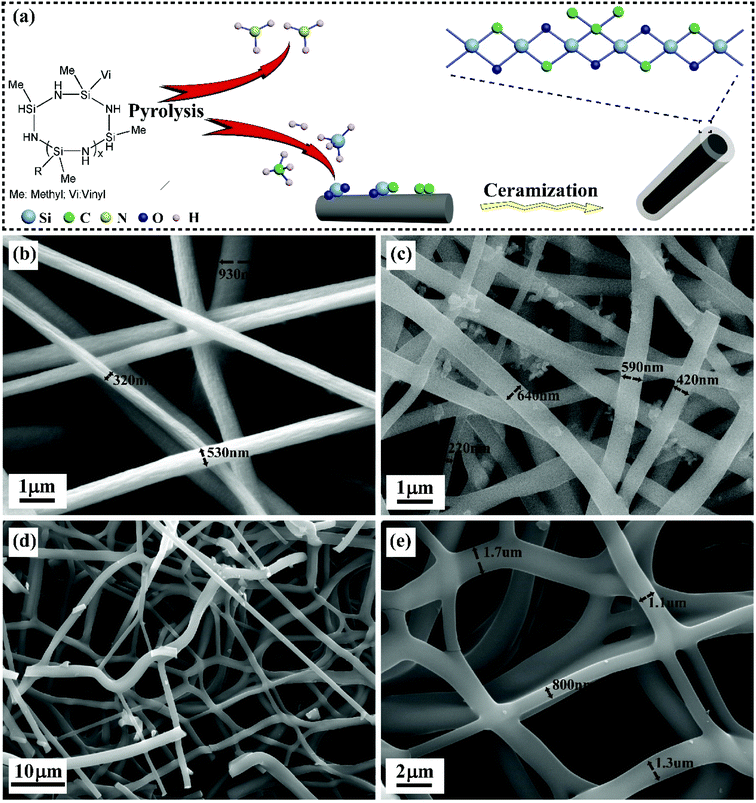
Fig. 1a depicted the synthesis process of CFs coated by SiOC ceramics. The organic functional groups of PSN were interaction, rearrangement, and recombination occurred in the pyrolysis process from 200 to 700 °C.20 The ammonia (NH3) was released because of the transamination reaction at a temperature from 200 to 400 °C.21 With the increase of temperature, hydrogen (H2), silane (SiH4), methane (CH4) and a small quantity of ethylene (C2H4) and acetylene (C2H2) were liberated due to the scissions of C–C, Si–C, Si–H, and C–H bonds at 400–700 °C.22 Furthermore, a small fraction of SiH4, CH4, C2H4, and C2H2 could be pyrolyzed, and then deposited on PAN fibers.23 It was notable that C–O–C, C![[double bond, length as m-dash]](https://www.rsc.org/images/entities/char_e001.gif) O could be formed within cyclized PAN in the oxidative stabilization process. At the same time, PAN-derived CFs were carbonized under Ar, SiH4, and CH4 atmosphere. Therefore, the interactions and reactions of Si–H, C–H, C–C bonds, and oxygen functional groups could form C–Si–O, O–Si–O and C–C bonds on the surface of CFs. Finally, the SiOC/CFs composites were developed after the stabilization and ceramization of SiOC, SiO2 and amorphous carbon. The probable reactions were proposed in eqn (S1)–(S4) (ESI†).
O could be formed within cyclized PAN in the oxidative stabilization process. At the same time, PAN-derived CFs were carbonized under Ar, SiH4, and CH4 atmosphere. Therefore, the interactions and reactions of Si–H, C–H, C–C bonds, and oxygen functional groups could form C–Si–O, O–Si–O and C–C bonds on the surface of CFs. Finally, the SiOC/CFs composites were developed after the stabilization and ceramization of SiOC, SiO2 and amorphous carbon. The probable reactions were proposed in eqn (S1)–(S4) (ESI†).
As shown in Fig. 1b, PAN fiber exhibited a typical circular morphology. The crude surface was owing to the evaporation of DMF solvent. These PAN fibers showed inhomogeneous size with a diameter in the range of 320–600 nm. The damp air induced static would deteriorate unstable voltage in the electrospinning process, so PAN fibers may become inhomogeneous because of the mutative and erratic electric force. In addition, these fibers lied randomly and formed a cross-linked network structure. Fig. 1c displayed PAN-derived CFs with the diameter of 220–600 nm corresponding to the volume shrinkage of PAN during carbonization process.24 The continuous CFs coated by SiOC ceramics were shown in Fig. 1d. The high magnification given in Fig. 1e displayed smooth fibers with the diameter of 0.8–1.7 μm.
The XPS spectra (Fig. 2) were carried out to ascertain the composition of SiOC/CFs products. As shown in Fig. 2a, the survey spectrum revealed that the SiOC coating was composed of Si, O, and C elements with a ratio of 1![[thin space (1/6-em)]](https://www.rsc.org/images/entities/char_2009.gif) :
:![[thin space (1/6-em)]](https://www.rsc.org/images/entities/char_2009.gif) 1.2
1.2![[thin space (1/6-em)]](https://www.rsc.org/images/entities/char_2009.gif) :
:![[thin space (1/6-em)]](https://www.rsc.org/images/entities/char_2009.gif) 1.7. Fig. 2b displayed the broad Si band (for Si 2p) and revealed the presence of different valence around Si atom arising from bonding with other elements, it could be deconvoluted into three bands around at 101.98, 102.88 and 103.48 eV, corresponding to C–Si–O, Si–O and O–Si–O bonds respectively.25 The analysis of the fitted C 1s band (Fig. 2c) suggested the emergence of peaks located at C–C (284.48 eV) and C–Si–O (284.88 eV) bonds.26 The chemical shift toward to a higher bonding energy of 284.88 eV responded a bonding configuration of C–Si–O, this was because the electronegative of O atom was higher than those of C and Si atoms. The spectrum of O 1s given in Fig. 2d showed two fitting peaks at 532.38 and 533.08 eV related to Si–O and SiO2 bonds.
1.7. Fig. 2b displayed the broad Si band (for Si 2p) and revealed the presence of different valence around Si atom arising from bonding with other elements, it could be deconvoluted into three bands around at 101.98, 102.88 and 103.48 eV, corresponding to C–Si–O, Si–O and O–Si–O bonds respectively.25 The analysis of the fitted C 1s band (Fig. 2c) suggested the emergence of peaks located at C–C (284.48 eV) and C–Si–O (284.88 eV) bonds.26 The chemical shift toward to a higher bonding energy of 284.88 eV responded a bonding configuration of C–Si–O, this was because the electronegative of O atom was higher than those of C and Si atoms. The spectrum of O 1s given in Fig. 2d showed two fitting peaks at 532.38 and 533.08 eV related to Si–O and SiO2 bonds.
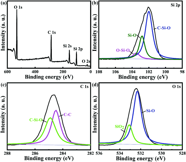 | ||
| Fig. 2 XPS spectra of full range scanning for SiOC/CFs composites: (a) survey spectrum; (b) Si 2p peak; (c) C 1s peak; and (d) O 1s peak. | ||
The Raman spectra of SiOC/CFs and CFs given in Fig. 3a were performed to confirm the existence of carbon. Two obvious peaks observed at 1340 and 1580 cm−1 were corresponding to D and G bands, indicating the graphitic structure. The G band originated from in-plane stretching of sp2 bonds, such as C–C bonds, and the D band was contributed to disorder graphite phase.26 It could be observed that the Raman shift of G band of SiOC/CFs was higher than that of CFs, this was because that G band of SiOC/CFs composites could be divided into G, D2 and D3 bands (Fig. 3b). The fitted G band of SiOC/CFs composites was located at 1577 cm−1, which was close to that of CFs. The D or D1, D2 bands were ascribed to disorder graphite lattice (A1g symmetry and E2g symmetry respectively), while D3 band originated from amorphous soot.27
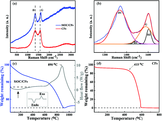 | ||
| Fig. 3 (a) The Raman spectra of SiOC/CFs and CFs, and (b) Raman spectrum of SiOC/CFs from 1100 to 1700 cm−1. The TG-DTA curves of (c) SiOC/CFs composites and (d) CFs under air. | ||
The TG-DTA were performed to investigate the thermal stability of SiOC/CFs and test the antioxidation function of SiOC coating. Fig. 3c showed the TG-DTA curves of SiOC/CFs products heated from room temperature to 1100 °C with a rate of 10 °C min under flowing air. The broad endothermic peak in the range of 30–350 °C showed that a weight loss about 7% was corresponding to the removal of water, and it was considered as a physical process. The exothermic peak occurred at 890 °C illustrated that a weight loss was about 15% in the temperature from 620 to 920 °C. And this weight loss was attributed to the oxidation of bulk amorphous carbon in the coating and exposed CFs (exothermic reactions). The weight increased a little starting at 920 °C, because the oxidation of C–Si phase could form SiO2 with a heavier molecular mass. Fig. 3d displayed the TG curve of CFs. It could be observed that CFs delivered the starting oxidation temperature at 415 °C and had been totally combusted at 600 °C. Based on the result of TG-DTA data, it revealed that the SiOC/CFs composites presented a better antioxidation property, moreover, and the SiOC coating could availably protect CFs from oxidizing at 415 °C and make CFs attractive for use in the high-temperature field.
To evaluate the microwave absorbing efficiency of SiOC/CFs composites, the reflection loss (RL) of the electromagnetic wave was calculated by the following eqn (1) and (2).
Zin = Z0(μr/εr)1/2![[thin space (1/6-em)]](https://www.rsc.org/images/entities/char_2009.gif) tanh[j(2πfd/c)(μr/εr)1/2] tanh[j(2πfd/c)(μr/εr)1/2] | (1) |
RL = 20![[thin space (1/6-em)]](https://www.rsc.org/images/entities/char_2009.gif) log|(Zin − Z0)/(Zin + Z0)| log|(Zin − Z0)/(Zin + Z0)| | (2) |
ε r was the relative complex permittivity, μr was the complex permeability, f was the frequency of microwave, d was the thickness of the absorber, c was the velocity of the electromagnetic wave in free space, Zin was the input impedance of the absorber, and Z0 was the impedance of air.28
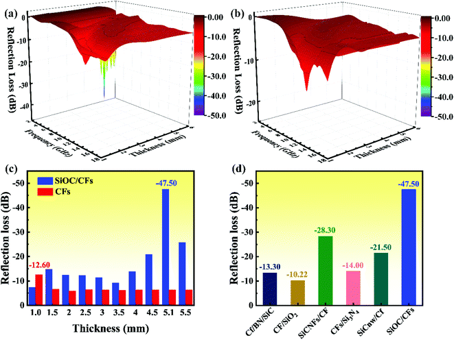
According to the eqn (2), the RL value below −10 dB revealed that 90% EM energy was attenuated and absorbed, furthermore, it was an effective and important parameter for evaluating the microwave absorption properties. As shown in Fig. 4a, the optimal RL of SiOC/CFs could reach −47.50 dB at 2.64 GHz with a thickness of 5.1 mm, and the EAB was obtained in the frequency of 2.2–3.4 GHz with a thickness of 3.7–6.0 mm and 6.8–14.8 GHz with a thickness of 1.3–3.0 mm. In Fig. 4b, the optimal RL of −12.60 dB for CFs was observed at 13.8 GHz with a thickness of 1.0 mm, and the EAB was from 13.1 to 14.3 GHz in the range of thickness from 0.9 to 1.1 mm. There was no doubt that the optimal RL value and effective bandwidth of composites had evidently improved a lot compared to those of CFs, especially in S-band (2–4 GHz). It was apparent that the RL values of SiOC/CFs were much lower than those of CFs in various layer thicknesses (Fig. 4c). Fig. 4d compared the MA performance between the SiOC/CFs and other Si-based CFs composites.15,16,29–31 The SiOC/CFs delivered an excellent MA performance among these composites. The detailed data of related references were listed in Table S1.† Above all, the obtained SiOC/CFs composites possessed an enhanced MA ability and would be a promising candidate for high-temperature MAMs.
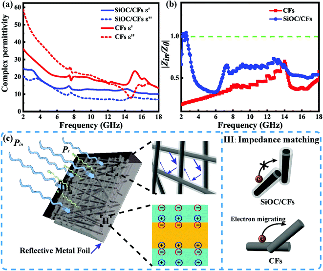
The complex permittivity was regarded as an important parameter to investigate the MA properties of SiOC/CFs composites, the relative complex permittivity of composites and CFs were given in Fig. 5a. The values of real (ε′) and imaginary (ε′′) parts of CFs were higher than those of SiOC/CFs composites. The ε′′ value was relevant to energy loss because of the rearrangement of electric dipole moment in electromagnetic filed,32 the ε′′ value for two samples showed a decreased trend in the frequency of 2–18 GHz. Fig. S1† showed the sketch of band gaps of CFs (conductor) and SiOC composites (semiconductor). The value of the band gap for the conductor was zero, and the SiC had a wide bandgap (2.3–3.4 eV).33 On one hand, the smaller band gap would give rise to decreasing Fermi energy, thus electrons at the valence band would be easier to jump into the conduction band, and then be polarization. On the other hand, the cross-linked CFs network formed a good galvanic circle, exacerbating the movement of electrons. The SiOC coating as a semiconductor formed a potential energy barrier between the cross-linked CFs, and the barrier could effectively prevent electrons jumping and migrating.34 Consequently, the complex permittivity of SiOC composites was lower than those of CFs. Fig. S2† exhibited the tangent loss (tan![[thin space (1/6-em)]](https://www.rsc.org/images/entities/char_2009.gif) δε = ε′′/ε′) curves of SiOC/CFs and CFs. The tan
δε = ε′′/ε′) curves of SiOC/CFs and CFs. The tan![[thin space (1/6-em)]](https://www.rsc.org/images/entities/char_2009.gif) δε values of CFs were higher than those of SiOC products, it meant that CFs created stronger attenuation ability for incident microwave than that of SiOC/CFs products. According to Debye theory, Cole–Cole semicircles (ε′′ versus ε′) of SiOC/CFs composites and CFs were plotted in Fig. S3† to discuss diversified dielectric loss mechanism, and one semicircle generally implied one relaxation process.35 There were seven continuous semicircles appeared for composites as presented in Fig. S3a.† And four semicircles were found for CFs in Fig. S3b.† On the one hand, SiOC coating could absorb microwave because of the polarization relaxation originated from defects, electrons, and dipoles. Especially, SiOC, SiO2 and free carbon in amorphous SiOC coating would result in dipolar polarization.19 On the other hand, the existence of interfaces between SiOC coating and CFs brought about interfacial polarization, which could boost the consumption of electromagnetic energy.36,37 The amorphous SiOC coating was consisted of SiOC, SiO2 and free carbon components. Therefore, a large number of grain boundaries within SiOC coating also made great contributions to improving interfacial polarization.38 Besides, the inner CFs of composites constructed a good galvanic circle, thus leading to a favorable conduction loss.39,40 Thus, there were much more polarization processes within SiOC/CFs composites. Meanwhile, an excellent candidate of MAMs not only possessed high attenuation efficiency but also had good impedance matching.41 As shown in Fig. 5b, the value of normalized input impedance (|Zin/Z0|) for composites was much higher than CFs. When the value of |Zin/Z0| was equal to 1, it meant the best impedance matching. As mentioned above, the cross-linked CFs network was propitious to the movement of electrons, while the SiOC coating as a barrier suppressed electrons jumping and migrating. Thus, an undesirable reflection occurred onto the surface of CFs due to the skin effect, and the SiOC coating could restrain skin effect originated from CFs, resulting in more microwave propagating into absorber.42 Although the tan
δε values of CFs were higher than those of SiOC products, it meant that CFs created stronger attenuation ability for incident microwave than that of SiOC/CFs products. According to Debye theory, Cole–Cole semicircles (ε′′ versus ε′) of SiOC/CFs composites and CFs were plotted in Fig. S3† to discuss diversified dielectric loss mechanism, and one semicircle generally implied one relaxation process.35 There were seven continuous semicircles appeared for composites as presented in Fig. S3a.† And four semicircles were found for CFs in Fig. S3b.† On the one hand, SiOC coating could absorb microwave because of the polarization relaxation originated from defects, electrons, and dipoles. Especially, SiOC, SiO2 and free carbon in amorphous SiOC coating would result in dipolar polarization.19 On the other hand, the existence of interfaces between SiOC coating and CFs brought about interfacial polarization, which could boost the consumption of electromagnetic energy.36,37 The amorphous SiOC coating was consisted of SiOC, SiO2 and free carbon components. Therefore, a large number of grain boundaries within SiOC coating also made great contributions to improving interfacial polarization.38 Besides, the inner CFs of composites constructed a good galvanic circle, thus leading to a favorable conduction loss.39,40 Thus, there were much more polarization processes within SiOC/CFs composites. Meanwhile, an excellent candidate of MAMs not only possessed high attenuation efficiency but also had good impedance matching.41 As shown in Fig. 5b, the value of normalized input impedance (|Zin/Z0|) for composites was much higher than CFs. When the value of |Zin/Z0| was equal to 1, it meant the best impedance matching. As mentioned above, the cross-linked CFs network was propitious to the movement of electrons, while the SiOC coating as a barrier suppressed electrons jumping and migrating. Thus, an undesirable reflection occurred onto the surface of CFs due to the skin effect, and the SiOC coating could restrain skin effect originated from CFs, resulting in more microwave propagating into absorber.42 Although the tan![[thin space (1/6-em)]](https://www.rsc.org/images/entities/char_2009.gif) δε of CFs was higher than that of SiOC/CFs, the MA performance of SiOC/CFs was much better than that of CFs owing to its better impedance matching.
δε of CFs was higher than that of SiOC/CFs, the MA performance of SiOC/CFs was much better than that of CFs owing to its better impedance matching.
The schematic representation of microwave absorption mechanism for SiOC/CFs was proposed in Fig. 5c. When incident microwave propagated on SiOC/CFs composites backed with a reflective metal, the incident microwave power (Pin) would be consisted of two parts, reflected (Pr) and absorbed (Pa) microwave power.10Pa was related to the double microwave absorption by SiOC and CFs. Pr was determined by interfacial impedance gap between air and absorber. The loss mechanism of composites was contributed to three parts. Initially, the multiple reflections occurred on fibers could extend routes of electromagnetic wave propagation in the absorber, which was propitious to the loss of microwave. Secondly, the diversified polarization relaxation processes would boost the dielectric loss. Thirdly, the favorable impedance matching would make more microwave propagate into absorber, leading to an enhanced MA performance.
4. Conclusions
In summary, the SiOC ceramics coating modified CFs had been successfully synthesized using a one-step precursor pyrolysis technique. The XPS results revealed that the SiOC coating was composed of SiOC, SiO2 and amorphous carbon phases. The SiOC ceramics coating not only effectively protected CFs from oxidizing, but also improved microwave absorbing ability. The optimal RL of composites was −47.50 dB at 2.64 GHz with a thickness of 5.1 mm, and the EAB was in the range of 6.8–14.8 GHz with the thin thickness of 1.3–3.0 mm. The enhanced MA performance could be attributed to multiple reflections in the cross-linked structure, various polarization relaxation processes, especially interfacial polarization, and the enhanced impedance matching effect. The fine antioxidation and MA performance of SiOC/CFs would make it attractive for applying in the high-temperature MA field.Conflicts of interest
There are no conflicts to declare.Acknowledgements
Haibin Zhang is grateful to the Foundation by the Recruitment Program of Global Youth Experts and the Youth Hundred Talents Project of Sichuan Province. This work is supported by the National Natural Science Foundation of China (Grant No. 91326102), the Science and Technology Development Foundation of China Academy of Engineering Physics (Grant No. 2013A0301012), the Science and Technology Innovation Research Foundation of Institute of Nuclear Physics and Chemistry.References
- E. Sano and E. Akiba, Carbon, 2014, 78, 463–468 CrossRef CAS.
- L. Wang, H. Xing, S. Gao, X. Ji and Z. Shen, J. Mater. Chem. C, 2017, 5, 2005–2014 RSC.
- T. Zhang, P. Zhou, B. Xiao, J. Zhang, G. Wen, B. Zhong and L. Xia, Ceram. Int., 2017, 43, 8603–8610 CrossRef CAS.
- R. Yang, B. Wang, J. Xiang, C. Mu, C. Zhang, F. Wen, C. Wang, C. Su and Z. Liu, ACS Appl. Mater. Interfaces, 2017, 9, 12673–12679 CrossRef CAS.
- T. Wu, Y. Liu, X. Zeng, T. Cui, Y. Zhao, Y. Li and G. Tong, ACS Appl. Mater. Interfaces, 2016, 8, 7370–7380 CrossRef CAS.
- T. Wang, H. Wang, X. Chi, R. Li and J. Wang, Carbon, 2014, 74, 312–318 CrossRef CAS.
- N. Li, G. W. Huang, Y. Q. Li, H. M. Xiao, Q. P. Feng, N. Hu and S. Y. Fu, ACS Appl. Mater. Interfaces, 2017, 9, 2973–2983 CrossRef CAS.
- G. Li, T. Xie, S. Yang, J. Jin and J. Jiang, J. Phys. Chem. C, 2012, 116, 9196–9201 CrossRef CAS.
- S. Zhao, L. Yan, X. Tian, Y. Liu, C. Chen, Y. Li, J. Zhang, Y. Song and Y. Qin, Nano Res., 2017, 11, 530–541 CrossRef.
- Y. Zhang, Y. Huang, T. Zhang, H. Chang, P. Xiao, H. Chen, Z. Huang and Y. Chen, Adv. Mater., 2015, 27, 2049–2053 CrossRef CAS.
- W.-L. Song, X.-T. Guan, L.-Z. Fan, Y.-B. Zhao, W.-Q. Cao, C.-Y. Wang and M.-S. Cao, Carbon, 2016, 100, 109–117 CrossRef CAS.
- R. Pillai, N. Batra, L. M. Manocha and N. Machinewala, Surf. Interfaces, 2017, 7, 113–115 CrossRef CAS.
- S. Masoudifar, M. Bavand-Vandchali, F. Golestani-Fard and A. Nemati, Ceram. Int., 2016, 42, 11951–11957 CrossRef CAS.
- M. Niu, H. Wang, L. Su, D. Zhang and J. Shi, Ceram. Int., 2016, 42, 10614–10618 CrossRef CAS.
- W. Zhou, L. Long, P. Xiao, C.-k. Jia and Y. Li, Surf. Coat. Technol., 2019, 359, 272–277 CrossRef CAS.
- M.-S. Cao, W.-L. Song, Z.-L. Hou, B. Wen and J. Yuan, Carbon, 2010, 48, 788–796 CrossRef CAS.
- W. Y. Duan, X. W. Yin, Q. Li, X. M. Liu, L. F. Cheng and L. T. Zhang, J. Eur. Ceram. Soc., 2014, 34, 257–266 CrossRef CAS.
- B. Du, C. He, J. Qian, M. Cai, X. Wang and A. Shui, J. Am. Ceram. Soc., 2019, 102, 7015–7025 CrossRef CAS.
- B. Du, C. He, A. Shui, X. Zhang and C. Hong, Ceram. Int., 2019, 45, 1208–1214 CrossRef CAS.
- Q. Li, X. Yin, W. Duan, B. Hao, L. Kong and X. Liu, J. Eur. Ceram. Soc., 2014, 34, 589–598 CrossRef CAS.
- S. R. Shah and R. Raj, Acta Mater., 2002, 50, 4093–4103 CrossRef CAS.
- D. Bahloul, M. Pereira and C. Gerardin, J. Mater. Chem., 1997, 7, 109–116 RSC.
- A. Krause, M. Grube, T. Mikolajick and W. M. Weber, ECS Trans., 2015, 70, 69–78 CrossRef CAS.
- L. Wang, Y. Yu, P. C. Chen, D. W. Zhang and C. H. Chen, J. Power Sources, 2008, 183, 717–723 CrossRef CAS.
- X. Zhang, X. Huang, G. Wen, X. Geng, J. Zhu, T. Zhang and H. Bai, Nanotechnology, 2010, 21, 385601 CrossRef.
- L. David, R. Bhandavat, U. Barrera and G. Singh, Nat. Commun., 2016, 7, 10998 CrossRef CAS.
- A. Sadezky, H. Muckenhuber, H. Grothe, R. Niessner and U. Pöschl, Carbon, 2005, 43, 1731–1742 CrossRef CAS.
- T. Zhang, S. Zeng, G. Wen and J. Yang, Microporous Mesoporous Mater., 2015, 211, 142–146 CrossRef CAS.
- W. Zhou, L. Long, P. Xiao, Y. Li, H. Luo and R.-m. Yin, Ceram. Int., 2017, 43, 5628–5634 CrossRef CAS.
- H. Luo, W. Chen, W. Zhou, L. Long, L. Deng, P. Xiao and Y. Li, Ceram. Int., 2017, 43, 12328–12332 CrossRef CAS.
- R. Wu, Z. Yang, M. Fu and K. Zhou, J. Alloys Compd., 2016, 687, 833–838 CrossRef CAS.
- H. Sun, R. Che, X. You, Y. Jiang, Z. Yang, J. Deng, L. Qiu and H. Peng, Adv. Mater., 2014, 26, 8120–8125 CrossRef CAS.
- G. Polupan and T. V. Torchynska, Thin Solid Films, 2010, 518, S208–S211 CrossRef CAS.
- Z. Wei, X. Peng, L. Yang, L. Heng and H. Wen, J. Inorg. Mater., 2014, 29, 1093–1098 CrossRef.
- X. Jian, B. Wu, Y. Wei, S. X. Dou, X. Wang, W. He and N. Mahmood, ACS Appl. Mater. Interfaces, 2016, 8, 6101–6109 CrossRef CAS.
- G. Ma, Y. Duan, Y. Liu and S. Gao, J. Mater. Sci.: Mater. Electron., 2018, 29, 17405–17415 CrossRef CAS.
- H. Pang, R. P. Sahu, Y. Duan and I. K. Puri, Diamond Relat. Mater., 2019, 96, 31–43 CrossRef CAS.
- L. Huang, Y. Duan, X. Dai, Y. Zeng, G. Ma, Y. Liu, S. Gao and W. Zhang, Small, 2019, 1902730 CrossRef.
- H. Pang, A. M. Abdalla, R. P. Sahu, Y. Duan and I. K. Puri, J. Mater. Sci., 2018, 53, 16288–16302 CrossRef CAS.
- Y. Duan, Y. Liu, Y. Cui, G. Ma and W. Tongmin, Prog. Org. Coat., 2018, 125, 89–98 CrossRef CAS.
- W. Duan, X. Yin, F. Ye, Q. Li, M. Han, X. Liu and Y. Cai, J. Mater. Chem. C, 2016, 4, 5962–5969 RSC.
- D. Ding, Y. Wang, X. Li, R. Qiang, P. Xu, W. Chu, X. Han and Y. Du, Carbon, 2017, 111, 722–732 CrossRef CAS.
Footnote |
| † Electronic supplementary information (ESI) available. See DOI: 10.1039/c9ra06166e |
| This journal is © The Royal Society of Chemistry 2019 |

