 Open Access Article
Novel stretchable thermochromic transparent heaters designed for smart window defroster applications by spray coating silver nanowire†
Loganathan Veeramuthu‡
a,
Bo-Yu Chen‡a,
Ching-Yi Tsai‡a,
Fang-Cheng Liang‡a,
Manikandan Venkatesana,
Dai-Hua Jianga,
Chin-Wen Chen a,
Xingke Cai
 *b and
Chi-Ching Kuo
 *a
*a
aInstitute of Organic and Polymeric Materials, Research and Development Center of Smart Textile Technology, National Taipei University of Technology, 10608 Taipei, Taiwan. E-mail: kuocc@mail.ntut.edu.tw; Fax: +886-2-27317174; Tel: +886-2-27712171 ext. 2407
bInstitute for Advanced Study, Shenzhen University, Shenzhen, Guangdong 518060, P. R. China. E-mail: cai.xingke@szu.edu.cn
First published on 4th November 2019
Abstract
A productive and novel method for fabricating stretchable transparent heaters with recognised thermochromic properties using commercially available thermochromic ink (TM-55-blue) and silver nanowire (AgNW)-coated polydimethylsiloxane (PDMS) is proposed. Lower resistance, elevated heat generation, and higher transparencies were the expected essential prerequisites for the fabrication of items such as smart windows and window defrosters. AgNW-coated PDMS (hereafter PH devices) satisfied the essential prerequisites but did not produce sufficient color change. In addition to the appreciable electrical and optical characteristics and mechanical robustness, observable color changes represent a critical factor in effortless temperature monitoring by the heating device. Blending TM-55-blue thermochromic ink with PDMS (PBH device) improves the heating rate and color transformation and promotes the ultralow response time appreciably. More notably, it produces a visible transformation from blue to colorless. Color changes visible to the naked eye, ultralow response time, and heating rate represent valuable features for deploying the PBH devices as window defrosters and in smart window applications.
1. Introduction
Stretchable heaters have represented a field of interest over the past few years due to their applicability in various fields, such as in defrosters, smart windows, thermotherapy pads, smart garments, and personal health care equipment. Researchers have endeavored to fabricate devices with both high transparency and high conductivity. ITO has been conquering arenas relating to equipment such as solar cells,1 light emitting devices,2 field emission transistors,3 photodetectors,4 supercapacitors,5 transparent heaters,6 and gas sensors7,8 due to its low sheet resistance and high transparency. ITO possesses high brittleness that limits its applicability in flexible and stretchable electronics. It also possesses certain limitations such as slow heating and cooling rates attributable to lower thermal conductivity and limited thermal stability.9–11 In addition, the increasing cost of the rare element indium incentivizes researchers to search for alternatives to ITO.Carbon-based materials such as carbon nanotubes,12,13 and graphene14,15 were utilized as transparent conductive electrodes in the fabrication of transparent heaters. The limitation associated with carbon-based electrodes is their high sheet resistance. Lower sheet resistant heaters can stem the substrate to undergo Joule heating, elevating temperature maximally with low input voltage. Conductive polymer offers superior performance because of its higher conductivity, light weight, and solution processability, for example. Post-treatment of PEDOT PSS, such as acid treatment and chemical reduction, has significant effects in improving thermoelectric properties.16 This post-treatment hampers the material's applicability on an industrial scale, owing to corrosive treatment, time management, and other troublesome factors.
Metallic nanowires have gained attention due to characteristics such as their high conductivity, high transmittance, reduced sheet resistance, robustness, large-scale synthesis, and shapeability. Metal nanowire-based heaters present faster thermal responses even under lower voltages. In particular, AgNWs possess superior properties such as excellent flexibility, stretchability, high conductivity, high transparency, easily tunable nanowire synthesis, and relative stability in terms of oxidation.17–19 For generating nanowire networks, the spray-coating method possesses remarkable advantages compared with other techniques. Spray coating bestows several benefits such as simplicity, time saving, homogeneity in distribution, applicability to 3D-structured materials, flexible operation, waste minimization of functional inks and low-cost techniques for utilization in large-scale processes.20–22 Silver nanowire (AgNW) network density can be adjusted by varying the spray-coating duration, which controls the optoelectronic properties of the film.20,23
Fabricating functional heaters still remains challenging in real-time applications because of flexibility and stretchability restrictions. For smart heaters to be utilized under adverse conditions, the heaters' characteristics must include stretchability, homogeneous heat generation, strain tolerance, low hysteresis, endurance, and repeatability. Hong and colleagues fabricated stretchable and transparent heaters using laser ablation patterning of AgNW on a PDMS substrate, and conferred advantages such as high flexibility, stretchability, and transparency.24 An and colleagues utilized CuZr metallic glasses in the form of metallic nanotroughs for fabricating stretchable heaters, resulting in considerable stretchability owing to the high elastic limit of CuZr metallic glasses.25 Huang et al. designed a brilliant flexible thermochromic smart window with good mechanical stability towards various deformations.26
To date, only a few studies have reported on the inclusion of thermochromic ink onto stretchable heaters. Integration of thermochromic ink may enable better results in fabricating smart heaters, smart windows and window defrosters. More recently, our group Cu/Ag core/shell nanofibrous films exhibiting the ultra-low sheet resistance, improved stability and robustness to find the potential application in flexible electronics.27
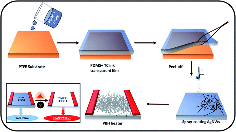
In this study, we fabricated two stretchable heaters, namely a conventional PDMS heating (PH) device and a novel TC-PDMS blended heating (PBH) device by employing a simple spray-coating technique. Fig. 1 and S1† illustrate the fabrication process of the PBH and PH heating devices. The detailed fabrication processes for the PBH and PH are discussed in the experimental section. PDMS was chosen as a substrate because of its inherent flexibility, elasticity, biocompatibility, and nontoxicity, for example. The addition of a crosslinker expedites the bond formation between PDMS and thermochromic ink (TM-55-blue) to form thermochromic ink incorporated PDMS substrate (TC-PDMS). Thermochromic ink (TM-55-blue) was chosen on the basis of considerations such as its low transition temperature (31 °C), appropriateness toward various substrates, and high heat and UV resistance. Commercially available AgNWs were spray-coated over the TC-PDMS substrate. AgNWs possess considerably lower sheet resistance, which directly reduces the thermal resistance for the effective transduction of electrical energy into heat energy, even at much lower applied potentials. Through this fabrication technique, we integrated both heating and thermochromism into our generated novel PBH device. Through comparing PH devices and PBH devices, it was revealed that the PBH exhibits high heating ability and retains considerable stability under various applied biases. The spray-coating time for AgNWs and AgNW density influence the sheet resistance and transmittance of the fabricated PH and PBH devices. The ultrafast heating rate and the thermochromism exhibited by fabricated PBH devices verify their credible potential in window defrosters and smart window applications. This research will remain instrumental for designing safety-assisting devices, smart windows, and defrosters.
2. Experimental section
2.1 Materials
PDMS precursors and isopropyl alcohol were purchased from Bio-Cando Inc. and J.T. Baker Chemical Co. AgNWs suspension was manufactured by Zhejiang Kechuang Advanced Materials Technology Co., Ltd (it is diluted to 0.66 wt% in IPA for further use). A 033G spray gun (Fuso Seiki Co., Ltd) was utilized for spray coating. Commercially available thermochromic TM-55-blue ink was purchased from New Prismatic Enterprise Co., Ltd.2.2 Fabrication of pristine PDMS substrates
A PDMS film was prepared by mixing a PDMS base solution and curing agent at a 10![[thin space (1/6-em)]](https://www.rsc.org/images/entities/char_2009.gif) :
:![[thin space (1/6-em)]](https://www.rsc.org/images/entities/char_2009.gif) 1 ratio. The resulting solution was conditioned in a vacuum chamber for 30 min to remove bubbles. PDMS substrates were fabricated by casting the solution onto flat glass, followed by curing at 60 °C overnight. Cured PDMS films were reduced to 2 cm × 2.5 cm dimensions, oxidized in air plasma at 300 mTorr and 120 W for 60 s, and the films were immediately soaked in isopropyl alcohol. Oxidized PDMS films were peeled away from the flat glass and dried on a hot plate.
1 ratio. The resulting solution was conditioned in a vacuum chamber for 30 min to remove bubbles. PDMS substrates were fabricated by casting the solution onto flat glass, followed by curing at 60 °C overnight. Cured PDMS films were reduced to 2 cm × 2.5 cm dimensions, oxidized in air plasma at 300 mTorr and 120 W for 60 s, and the films were immediately soaked in isopropyl alcohol. Oxidized PDMS films were peeled away from the flat glass and dried on a hot plate.
2.3 Preparation of pristine PH device
This study utilized AgNWs with an average diameter of 55–75 nm and length of 20–40 μm dispersed in isopropyl alcohol. Spray coating was performed at a distance of 10 cm above the PDMS substrate with a spray gun at room temperature and atmospheric pressure. AgNW dispersion was sprayed for 15, 30, and 60 s on the pristine PDMS substrate, and copper films were subsequently pasted using Ag paste to generate the pristine PH device.2.4 PBH device preparation
Commercial thermochromic TM-55-blue ink was blended with PDMS–hexane solution and stirred for 24 h at room temperature and atmospheric pressure. After the addition of the curing agent, the resultant solution was stirred for 30 min. Subsequently, casting, oxidation, and AgNW spray coating (spraying for 15, 30, and 60 s) were conducted as demonstrated in the PH device fabrication process to create the PBH device.2.5 Characterization
PDMS and TC-PDMS films were characterized by scanning electron microscopy (SEM) (Hitachi S-4800). Plasma treatment was used on both the films with delta TP04 to create the hydrophilic substrate. Oxidized PDMS and TC-PDMS films were spray-coated using a spray gun (RichPen, Model 033 G). Absorbance and transmittance of TC-PDMS (with different ratios of thermochromic ink) were studied using a UV-visible spectrometer (Hitachi U-4100). Sheet resistance was measured for the initial and stretched states of the films using a Keithley 4200 semiconductor parametric analyzer. The insertion of copper electrodes allowed the device to establish contact between the alligator clip and the heater, and the temperature was monitored continuously by employing a temperature probe (TES-1306) and an infrared (IR) camera (FLIR E30) simultaneously. An ice cabinet was employed for the defrosting experiments. The time taken to defrost the ice was measured using a digital timer.3. Results and discussion
3.1 Surface characteristics of pristine and thermochromic ink-blended PDMS
Fig. S2† depicts the SEM images of pristine PDMS and thermochromic ink-blended PDMS (TC-PDMS). The SEM image represents a smooth surface, which has a predominant function in accommodating AgNWs. Pristine PDMS and TC-PDMS cross-sectional SEM images illustrate the dispersivity of PDMS (Fig. S3a and b†). A comparison between pristine PDMS with TC-PDMS evinced that dispersivity was elevated to a greater extent in the TC-PDMS substrate (Fig. S3b†). Emerging dispersivity and homogeneity in the TC-PDMS substrate might have contributed to the smooth surface morphology of the substrate, in accordance with the top-view FE-SEM image (Fig. S2b†).Pristine PDMS and TC-PDMS substrates were plasma-treated to clean their surfaces, imparting hydrophilicity to the substrates; this is considered to be a promising factor for AgNW spray coating. AgNWs was chosen on the basis of several promising advantages, including excellent intrinsic stretchability, high conductivity, high transparency, large-scale solution processability, and easy tunability.
3.2 Optimization of spray-coating time
A silver nanowire suspension solution was used to spray coat the pristine PDMS for three different durations: 15 s (Device A), 30 s (Device B), and 60 s (Device C). Spray coating minimized the waste of functional inks in generating nanowires and made possible the creation of interpenetrating ultralong nanowires. Increasing the spray-coating duration is evidently favorable for the formation of dense nanowire networks. FE-SEM analyses of the prepared pristine PDMS-embedded AgNWs are illustrated in Fig. 2a–c, and these images confirm the expected trend. SEM imaging revealed that longer spraying times result in denser nanowire network formation (Fig. 2c). Higher transmittance, lower sheet resistance, and significantly low surface roughness have been achieved by exploiting spray-coating techniques.14,21,28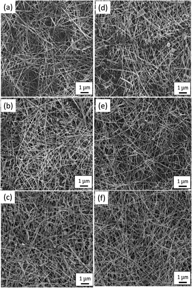 | ||
| Fig. 2 (a–c) Polydimethylsiloxane (PDMS) substrate spray-coated for (a) 15 s, (b) 30 s, and (c) 60 s; (d–f) thermochromic ink-blended PDMS substrate spray-coated for (d) 15 s, (e) 30 s, and (f) 60 s. | ||
TC-PDMS substrates were spray-coated with AgNWs for three different durations: 15 s (Device D), 30 s (Device E), and 60 s (Device F), as shown in Fig. 2d–f. The spray-coating method permitted similar surface AgNW embedment on the TC-PDMS substrate (as observed for pristine PDMS). Similar surface observation features strongly corroborate that the TC-PDMS substrate is suitable for fabricating the heating device framework in place of conventional pristine PDMS, which lacks sufficient photochromism.
3.3 Electrical and optical performance of AgNW-coated TC-PDMS
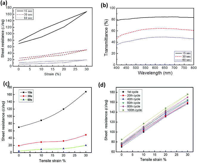
We further studied the electrical and optical performances of the AgNW-coated TC-PDMS substrates (Devices D, E, and F), portrayed in Fig. 3. Data were furnished with sheet resistance, and the transmittance plot demonstrates the utility of the thermochromic heater. The electrical sheet resistance measurements were calculated under the various applied strains (10%, 20%, and 30%) for Devices D, E, and F (Fig. 3a). The sheet resistance increases by approximately 80 Ω sq−1 when Device D undergoes tensile straining to 30%. On relaxation, the resistance returns to its initial value without any significant change. Device E was also able to restore the sheet resistance after relaxing from strain. Device E's sheet resistance inclination was relatively low compared with that of Device D: the elevation in sheet resistance was approximately 20 Ω sq−1. Device F conserved almost the same sheet resistance over the entire 30% elongation. This lowered hysteresis suggests reliable electrical performance by the AgNW-coated TC-PDMS even for a 30% stretched state.Transmittance variation over the entire visible region on Devices D, E, and F feature in Fig. 3b. Wide and flat transmittance over a broad range is desirable for light-emitting-device and solar-cell-panel fabrication. Device D exhibits higher transmittance compared with Devices E and F. Increasing network density evidently causes a decrease in transmittance. This outcome agrees with other reports.21,27,29 Device D may be considered the most suitable heating device (compared with Devices E and F) because of its higher transparency and considerably lower sheet resistance.
Verifying resistance stability of the device under strain is essential. Sheet resistances for Devices D, E, and F were analyzed under strains of 10%, 20%, and 30% (Fig. 3c). The sheet resistance increased from ∼70 Ω sq−1 to ∼170 Ω sq−1 (more than twofold increment). The other two devices, Devices E and F, exhibited comparatively lower sheet resistance. Sheet resistance stability was examined by measuring the sheet resistance for each 20 cycles and is plotted in a graph (Fig. 3d). The observed results for sheet resistance portray the stability of the fabricated PBH device.
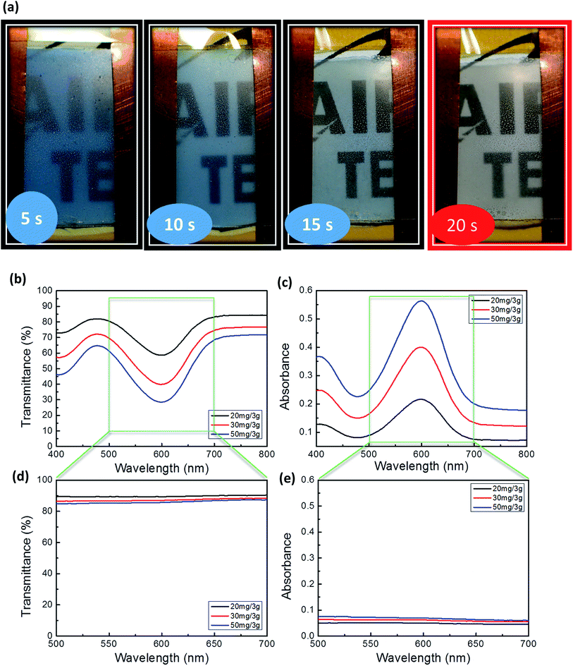
DC voltage was applied to the copper terminals of the fabricated device using the alligator clips through the copper terminals. On applying the potential, transparencies were achieved following the attainment of transition temperature (31 °C). PBH changes from blue to transparent when lower voltages of 5 V are applied (Fig. 4a), in accordance with transmittance and absorbance peaks after voltage application (Fig. 4b–e). Devices D was initially fabricated with a TC-PDMS blending ratio of 20 mg/3 g (TC ink![[thin space (1/6-em)]](https://www.rsc.org/images/entities/char_2009.gif) :
:![[thin space (1/6-em)]](https://www.rsc.org/images/entities/char_2009.gif) PDMS). Devices G and H were also fabricated with different ratios of thermochromic TM 55 blue ink
PDMS). Devices G and H were also fabricated with different ratios of thermochromic TM 55 blue ink![[thin space (1/6-em)]](https://www.rsc.org/images/entities/char_2009.gif) :
:![[thin space (1/6-em)]](https://www.rsc.org/images/entities/char_2009.gif) PDMS (30 mg/3 g and 50 mg/3 g). Fig. S4† shows photographs of the thermochromic heaters: Device D, Device G, and Device H. The color of the thermochromic heater intensified when the concentration of thermochromic ink in the blended films was increased.
PDMS (30 mg/3 g and 50 mg/3 g). Fig. S4† shows photographs of the thermochromic heaters: Device D, Device G, and Device H. The color of the thermochromic heater intensified when the concentration of thermochromic ink in the blended films was increased.
Optical properties were measured on the PBH device before (Fig. 4b and c) and after the potential was applied (Fig. 4d and e) using UV-visible spectroscopy. Absorption and transmittance peaks exhibited by Devices D, G, and H before the application of potential complies with the existence of blue color. When voltage was applied, the absorption was almost zero (Fig. 4e), and transmittance was observed to be approximately 90% (Fig. 4d) (constant over the entire visible spectrum), which was considered to be the primary criterion for use in applications such as window defrosters and smart windows. The results in Fig. 4d suggest that among Devices D, G, and H, Device D constitutes the best proposal, owing to its suitable transparency (90%). Such visual color changes have been utilized in several applications, including chromogenic sensors and heavy metal detectors, which has been discussed in numerous studies. Our group fabricated such a system to detect heavy metals such as Cu, Hg, and Fe.30–32
3.4 Heating performance of the fabricated PBH device
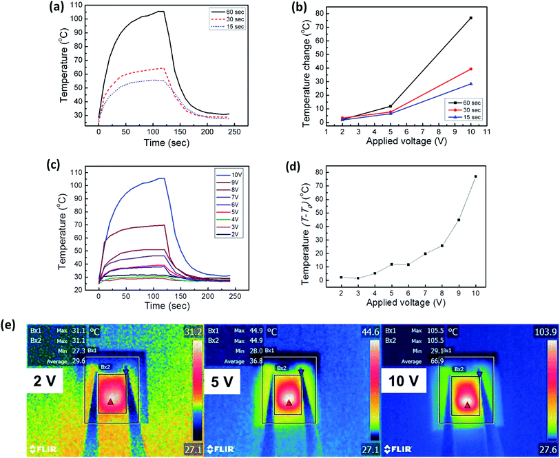
Devices D, E, and F are of great interest because of their lowered sheet resistances and low hysteresis. Considerable attention has been given by various groups to transparent heaters, and their results rely upon the reduced sheet resistance. We therefore applied 10 V across the copper terminals and monitored the heating performance of Devices D, E, and F.Generally, many studies have analyzed transparent heaters based on the Joule's law of heating. According to Joule's law, heaters' temperatures increase considerably by restricting the sheet resistance. In our case, we follow the same trend as observed in other literatures. As it is evidenced from lowered sheet resistance observed ultimately contributed to the maximum saturation temperature within a shorter response time (Fig. 5a). Device F exhibited a maximum temperature of approximately 110 °C which compares favorably with that of Device E (approximately 60 °C) and D (approximately 50 °C). Device D and E exhibited limited heating efficiency because of the internal resistance between the AgNW junctions.
The existence of junctions is apparent when the density of AgNWs is increased. On stretching, the cracks developing on 30 s and 60 s spray-coated substrates were visible with the naked eye (Fig. S5†) because of the higher AgNW density and the interconnected AgNW ruptures that occur more predominantly. On the other hand, control PDMS exhibited lower heating rate (Fig. S6†) whereas TC-PDMS device exhibit relatively higher heating rate because of the following two reasons: the first cause for such increase in heating rate was due to the enhanced compatibility between the TC-PDMS and AgNWs. A comparison between pristine PDMS with TC-PDMS evinced that dispersivity was elevated to a greater extent in the TC-PDMS substrate (Fig. S3b†). The second cause is that the dispersion facilitates the better AgNWs spray distribution thereby producing the enhanced heating rate.
The results in Fig. 5b suggest that the temperature rise on an increase in the potential from 2 V to 5 V was nearly 15 °C for Device F, whereas it was less than 5 °C for Devices E and E. On increasing the voltage to 10 V, we observed a temperature rise of approximately 75 °C for Device F (Fig. 5d). Devices E and D exhibited temperature rises of only approximately 40 °C and 25 °C, respectively. The results obtained corroborate that the heat-elevating performance of Device F tended to escalate drastically on biasing the heater to 10 V (three times greater than Device D).
3.5 Highlighted features of PBH devices
The versatile nature of PBH devices under applied potential biases was established by studying the thermochromic heater under different applied potential biases (Fig. 5c). The response time of a heater is defined as the time required to reach a steady-state temperature when starting from room temperature, and this response time is considered a promising factor in evaluating the heater's performance. Minimizing response time is desirable for fabricating a superior device. The temperature of the PBH device increased abruptly once constant voltages were applied, stabilizing within 20 s. Ultra-low response time is a considerable benefit of our heating device. The ultrafast response of our fabricated heater can be compared with the outcomes reported in other papers.33–41 An ultralow response time for the photochromic heater color change was illustrated with the help of the ESI Video M1.† This rapid thermochromic transition characteristic furthermore adds value to our fabricated PBH device. We suspect this accelerated response to be related to the thickness of the heating device. Such visual color changes were utilized in several applications such as chromogenic sensors and heavy metal detectors, as discussed in the literature. High transmittance and rapid response are credulous requirements for reliable heaters to be used in defrosters and in smart window applications. In addition, heating inhomogeneity constituted a major problem in thermotherapy and heating applications; we verified heating homogeneity with an IR camera. Fig. 5e depicts the PBH device heating homogeneity in the absence of any localized hotspots. The thermal IR camera image reveals the homogeneity of the temperature distribution on the PBH device. Hotspots present in the heating device may harm users in some wearable heating devices. Apart from 2 V, 5 V, and 10 V, the remaining biased PBH device images feature in Fig. S7.† As our PBH device fulfills all of the necessary criteria mentioned herein, we have made advancements in elucidating the processes of defrosting experiments.3.6 Applicability of the PBH device
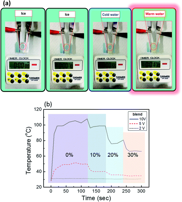
The defrosting experiment using PBH devices demonstrates their heating and thermochromic characteristics (Fig. 6a). A piece of ice was placed on top of the PBH device and was heated by applying 5 V. The ice completely melted within 55 s and turned hot within 90 s. In addition, color transformation was visually demonstrated with this defrosting experiment. Color transformation starts within 10 s and is completed within 15 s, as seen in the ESI Movie M1.† We designed the PBH device, a stretchable transparent heater with thermochromic properties, such that its credulous characteristics make it suitable for defrosting applications, even with low potential. Heating stability was furthermore tested by switching the device from 0 V to 10 V under various applied strains (0–30%). The PBH devices were allowed to undergo tensile elongation (10–30%) and the temperature was monitored. The heat-generating capability of a PBH device under three different strains was studied, and the results appear in Fig. 6b. The temperature decreases as tensile elongation increases from 0% to 30% because of nanowire junction failures. This temperature deterioration trend complies with results observed in other works.24,25,37 The heat-retaining capacity of the fabricated device upon applied tensile elongation can be quantified using temperature decay (%). This temperature decay (%) can be calculated using the following formulae:where Tinitial is the temperature observed upon 0% elongation of the heater device, Telongation is the temperature observed with the heater device subject to various elongations (for example 10%, 20%, and 30%). The results are collectively listed in Tables 1 and S1.† The heat-retaining capacity of both the PH and the PBH device are almost comparable (only slight deviations were observed with 30% stretching). Fig. 7 and ESI Movie M1† elucidates the credibility of our novel PBH device including heat generation, faster response, thermochromic switching ability along with 30% stretchable features. In addition, our novel PBH device works flawless without causing harm to heat generation and their corresponding color transition for 10 repetitive cycles proving its excellent lifetime applicability (Fig. S8†). Therefore, our novel PBH device offers a potential alternative to commercial PDMSs, with additional thermochromic properties having plausible bright pathways for use in temperature monitors, thermotherapy, activating filters, and smart homes.
| S. no | Voltage (V) | Temperature °C (0% stretch) | Temperature °C (30% stretch) | Temperature decay% (30%) |
|---|---|---|---|---|
| 1 | 2 | 31 | 30 | 3% |
| 2 | 5 | 51 | 34 | 33% |
| 3 | 10 | 107 | 66 | 38% |
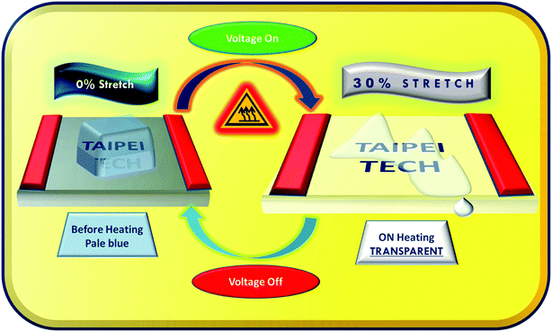 | ||
| Fig. 7 Schematic representation illustrates the heating, stretching, and thermochromic switching characteristics of the PBH device. | ||
4. Conclusion
We have presented a stretchable heater with desirable credentials such as high transparency, favorable photochromic properties, high stability, and rapid heating rate. Comparing our novel PBH device with conventional PH devices evidences the superiority of the novel PBH device. The dependence of nanowire network density on sheet resistance and transmittance was studied and optimized to produce an energy-efficient transparent stretchable heater. In addition, an ultralow response time of 20 s further elevated the utility of the fabricated heating device. The color transition was noticeable even at an extremely low temperature (31 °C), meaning that our PBH device is able to compete with other smart window applications. Considering the heating stability, homogeneity, robustness, and high transparency of our PBH device, it is a promising candidate for use in the design of outdoor displays, defoggers, and smart windows; its use may also be extrapolated for the development of energy-efficient transparent electrodes used in LEDs, OFETs, solar cells, touchscreens, and other such devices.Conflicts of interest
The authors declare no conflict of interest.Acknowledgements
This work was supported by the Ministry of Science and Technology, Taiwan (contracts: MOST 106-2221-E-027-119-MY3, MOST 105-2221-E-027-134- and MOST 104-2113-M-027-007-MY3), and National Taipei University of Technology and Shenzhen University Joint Research Program, (NTUT-SZU-108-01).References
- O. Malinkiewicz, A. Yella, Y. H. Lee, G. M. Espallargas, M. Graetzel, M. K. Nazeeruddin and H. J. Bolink, Nat. Photonics, 2013, 8, 128–132 CrossRef.
- M.-Y. Huang, L. Veeramuthu, C.-C. Kuo, Y.-C. Liao, D.-H. Jiang, F.-C. Liang, Z.-L. Yan, R. Borsali and C.-C. Chueh, Org. Electron., 2019, 67, 294–301 CrossRef CAS.
- M. Shariati, Biosens. Bioelectron., 2018, 105, 58–64 CrossRef CAS PubMed.
- A. Waleed, M. M. Tavakoli, L. Gu, S. Hussain, D. Zhang, S. Poddar, Z. Wang, R. Zhang and Z. Fan, Nano Lett., 2017, 17, 4951–4957 CrossRef CAS.
- F. Alvi, M. K. Ram, P. A. Basnayaka, E. Stefanakos, Y. Goswami and A. Kumar, Electrochim. Acta, 2011, 56, 9406–9412 CrossRef CAS.
- K. Im, K. Cho, J. Kim and S. Kim, Thin Solid Films, 2010, 518, 3960–3963 CrossRef CAS.
- S.-M. Lee, Y.-S. Lee, C.-H. Shim, N.-J. Choi, B.-S. Joo, K.-D. Song, J.-S. Huh and D.-D. Lee, Sens. Actuators, B, 2003, 93, 31–35 CrossRef CAS.
- S. Xu and Y. Shi, Sens. Actuators, B, 2009, 143, 71–75 CrossRef.
- H.-G. Im, S. Jeong, J. Jin, J. Lee, D.-Y. Youn, W.-T. Koo, S.-B. Kang, H.-J. Kim, J. Jang, D. Lee, H.-K. Kim, I.-D. Kim, J.-Y. Lee and B.-S. Bae, NPG Asia Mater., 2016, 8, e282 CrossRef CAS.
- M. Singh, T. R. Rana, S. Kim, K. Kim, J. H. Yun and J. Kim, ACS Appl. Mater. Interfaces, 2016, 8, 12764–12771 CrossRef CAS.
- C. Celle, C. Mayousse, E. Moreau, H. Basti, A. Carella and J.-P. Simonato, Nano Res., 2012, 5, 427–433 CrossRef CAS.
- J. Yan and Y. G. Jeong, Mater. Des., 2015, 86, 72–79 CrossRef CAS.
- J. Luo, H. Lu, Q. Zhang, Y. Yao, M. Chen and Q. Li, Carbon, 2016, 110, 343–349 CrossRef CAS.
- M. Cao, M. Wang, L. Li, H. Qiu and Z. Yang, ACS Appl. Mater. Interfaces, 2018, 10, 1077–1083 CrossRef CAS.
- S.-Y. Lin, T.-Y. Zhang, Q. Lu, D.-Y. Wang, Y. Yang, X.-M. Wu and T.-L. Ren, RSC Adv., 2017, 7, 27001–27006 RSC.
- J. Zhao, D. Tan and G. Chen, J. Mater. Chem. C, 2017, 5, 47–53 RSC.
- W. Lan, Z. Yang, Y. Zhang, Y. Wei, P. Wang, A. Abas, G. Tang, X. Zhang, J. Wang and E. Xie, Appl. Surf. Sci., 2018, 433, 821–828 CrossRef CAS.
- H. Wang, N. Sui, X. Bai, Y. Zhang, Q. Rice, F. J. Seo, Q. Zhang, V. L. Colvin and W. W. Yu, J. Phys. Chem. Lett., 2018, 9, 4166–4173 CrossRef CAS.
- J. Xiong, S. Li, Y. Ye, J. Wang, K. Qian, P. Cui, D. Gao, M. F. Lin, T. Chen and P. S. Lee, Adv. Mater., 2018, e1802803, DOI:10.1002/adma.201802803.
- Z. Ding, V. Stoichkov, M. Horie, E. Brousseau and J. Kettle, Sol. Energy Mater. Sol. Cells, 2016, 157, 305–311 CrossRef CAS.
- F. C. Liang, Y. W. Chang, C. C. Kuo, C. J. Cho, D. H. Jiang, F. C. Jhuang, S. P. Rwei and R. Borsali, Nanoscale, 2019, 11, 1520–1530 RSC.
- J.-G. Lee, J.-H. Lee, S. An, D.-Y. Kim, T.-G. Kim, S. S. Al-Deyab, A. L. Yarin and S. S. Yoon, J. Mater. Chem. A, 2017, 5, 6677–6685 RSC.
- M. Lagrange, D. P. Langley, G. Giusti, C. Jimenez, Y. Brechet and D. Bellet, Nanoscale, 2015, 7, 17410–17423 RSC.
- S. Hong, H. Lee, J. Lee, J. Kwon, S. Han, Y. D. Suh, H. Cho, J. Shin, J. Yeo and S. H. Ko, Adv. Mater., 2015, 27, 4744–4751 CrossRef CAS.
- B. W. An, E. J. Gwak, K. Kim, Y. C. Kim, J. Jang, J. Y. Kim and J. U. Park, Nano Lett., 2016, 16, 471–478 CrossRef CAS.
- W. R. Huang, Z. He, J. L. Wang, J. W. Liu and S. H. Yu, iScience, 2019, 12, 333–341 CrossRef CAS.
- D. H. Jiang, P. C. Tsai, C. C. Kuo, F. C. Jhuang, H. C. Guo, S. P. Chen, Y. C. Liao, T. Satoh and S. H. Tung, ACS Appl. Mater. Interfaces, 2019, 11, 10118–10127 CrossRef CAS.
- P. Li, J. Ma, H. Xu, X. Xue and Y. Liu, J. Mater. Chem. C, 2016, 4, 3581–3591 RSC.
- J. van de Groep, P. Spinelli and A. Polman, Nano Lett., 2012, 12, 3138–3144 CrossRef CAS.
- F.-C. Liang, C.-C. Kuo, B.-Y. Chen, C.-J. Cho, C.-C. Hung, W.-C. Chen and R. Borsali, ACS Appl. Mater. Interfaces, 2017, 9, 16381–16396 CrossRef CAS.
- C.-J. Cho, S.-T. Lu, C.-C. Kuo, F.-C. Liang, B.-Y. Chen and C.-C. Chu, React. Funct. Polym., 2016, 108, 137–147 CrossRef CAS.
- B. Y. Chen, C. C. Kuo, Y. S. Huang, S. T. Lu, F. C. Liang and D. H. Jiang, ACS Appl. Mater. Interfaces, 2015, 7, 2797–2808 CrossRef CAS PubMed.
- J. Li, J. Liang, X. Jian, W. Hu, J. Li and Q. Pei, Macromol. Mater. Eng., 2014, 299, 1403–1409 CrossRef CAS.
- M. Patel, K. R. Chauhan, J. Kim, J.-W. Kim and D. Lim, Sens. Actuators, A, 2017, 267, 8–13 CrossRef CAS.
- W. Lan, Y. Chen, Z. Yang, W. Han, J. Zhou, Y. Zhang, J. Wang, G. Tang, Y. Wei, W. Dou, Q. Su and E. Xie, ACS Appl. Mater. Interfaces, 2017, 9, 6644–6651 CrossRef CAS.
- K. H. Yeoh, N. A. Talik, T. J. Whitcher, C. Y. B. Ng and K. L. Woon, J. Phys. D: Appl. Phys., 2014, 47, 205103 CrossRef.
- S. Choi, J. Park, W. Hyun, J. Kim, J. Kim, Y. B. Lee, C. Song, H. J. Hwang, J. H. Kim, T. Hyeon and D.-H. Kim, ACS Nano, 2015, 9, 6626–6633 CrossRef CAS.
- K.-Y. Shin, J.-Y. Hong, S. Lee and J. Jang, J. Mater. Chem., 2012, 22, 23404 RSC.
- N. Tiwari, A. Ankit, M. Rajput, M. R. Kulkarni, R. A. John and N. Mathews, Nanoscale, 2017, 9, 14990–14997 RSC.
- Q. Huang, W. Shen, X. Fang, G. Chen, J. Guo, W. Xu, R. Tan and W. Song, RSC Adv., 2015, 5, 45836–45842 RSC.
- X. Zhang, X. Yan, J. Chen and J. Zhao, Carbon, 2014, 69, 437–443 CrossRef CAS.
Footnotes |
| † Electronic supplementary information (ESI) available. See DOI: 10.1039/c9ra06508c |
| ‡ L. Veeramuthu, B.-Y. Chen, C.-Y. Tsai, and F.-C. Liang contributed equally to this work. |
| This journal is © The Royal Society of Chemistry 2019 |

