 Open Access Article
Micro-manganese as a weight agent for improving the suspension capability of drilling fluid and the study of its mechanism
Jingyuan Maab,
Peizhi Yuab,
Boru Xiaab and
Yuxiu An *ab
*ab
aSchool of Engineering and Technology, China University of Geosciences (Beijing), Haidian District, Beijing 100083, China. E-mail: anyx@cugb.edu.cn
bKey Laboratory of Deep Geo Drilling Technology, Ministry of Land and Resources, Beijing 100083, China
First published on 1st November 2019
Abstract
The contradiction between the sag stability of weighted materials and the rheological properties of drilling fluids is one of the main technical difficulties in high-density drilling fluids. Thus, understanding the suspension mechanism of weighting materials is the key to improving the sag stability of weighting materials. In this study, micro-manganese (Mn3O4) was compared with the commonly used weighting agent barite to study the suspension mechanism of Mn3O4. The weighting effect of Mn3O4 and barite was evaluated by static and dynamic sag tests, rheological property measurements and filtration property tests. The evaluation experiment results showed that the sag stability of Mn3O4 was better than that of barite, and Mn3O4 could significantly increase the suspension capacity of drilling fluids and improve their rheology property. The scanning electron microscopy (SEM) and other test results indicate that the small and uniform spherical structure of micro-manganese not only causes it to have less friction, but also intense Brownian motion in drilling fluid, which weakens the sag caused by gravity. The large specific surface area of Mn3O4 results in the strong adsorption of water molecules and polymers in drilling fluids, resulting in the formation of a hydrated film on the surface of the Mn3O4 particles and physical crosslinking with polymer chains. This prevents sagging caused by the adsorption of small particles to form large particles. The key findings of this work are expected to provide a basis for improving the sag stability of weighting materials in drilling fluids and better the application of micro-manganese in drilling fluids.
1. Introduction
Pressure control of the formation is critical in drilling operations. The pressure is typically controlled using high density minerals such as barite and hematite to increase the density of drilling fluids. However, the control of rheology and sag stability is one of the main technical difficulties in high-density drilling fluids. Sag refers to the sinking of the weighting material caused by factors such as gravity, resulting in significant changes in the density of the drilling fluid and deterioration of the performance of the drilling fluid.1,2 Both static sag that occurs when the drilling fluid is stopping circulating and dynamic sag, which happens in the circulation, can result in wellbore instability, stuck pipe and other problems.3–5 There are many factors affecting sag such as the design parameters of the well, and the performance of drilling fluids and weighting materials. Among them, the performance of drilling fluids is closely related to the selection of weighting materials.6,7Barite is the most commonly used weighting material to adjust the density of drilling fluid. However, the problems of filter cake thickening, increasing equivalent circulation density (ECD), excessive torque and friction caused by barite sagging often occur.8–10 In addition, the problems such as the poor rock carrying capability and the increase in friction caused by the sagging of barite are distinctive in all horizontal wells. Thus, if sagging is not effectively solved, it can cause great difficulties to the drilling process and increase the drilling cost. Accordingly, optimizing other weighting materials to replace barite is one of the effective ways to solve the problem of barite sagging. According to Stokes' formula (1) and the static shear force formula (2) for drilling fluid suspension weighting materials:
| v = d2(ρs − ρf)g/(18η) | (1) |
| πd2τ = (1/6)πd3(ρs − ρf)g | (2) |
Micro-manganese (Mn3O4) as a weighting material refers to ultrafine particles (Mn3O4) having an average particle diameter of less than 1 μm synthesized by blowing air through a molten metal during a process following the production of manganese metal.11 A unique advantage of micro-manganese particles is their extremely low size and high density (4.8 g cm−3). Also, their sag rate is much lower than that of barite, and thus they have excellent sag stability.21 In fact, there have been some studies on the feasibility of using Mn3O4 instead of barite as a weighting material. For example, some studies have shown that Mn3O4-weighted drilling fluids are less likely to cause corrosion to the drill bit and damage to the formations than barite-weighted drilling fluids.22–24 Furthermore, the acid solubility of Mn3O4 makes the filter cake formed by Mn3O4 easier to be removed than that formed by barite during the reservoir development process.25 However, there are still some problems in the use of micro-manganese, such as particle agglomeration, large fluid loss, and high cost.26–29 Researchers have conducted extensive research on the dispersibility of micro-manganese28,30–32 and the removal of its filter cake.33–36 However, existing research has focused on the use of micro-manganese in drilling fluids, and there is no detailed discussion on the suspension stability mechanism of Mn3O4. As is known, the biggest problem in high density drilling fluids is the sag of barite. The key to solving this problem is to replace the weighting material or increase the suspension capacity of barite. Thus, understanding the suspension mechanism of Mn3O4 can not only result in the better use of Mn3O4 in drilling fluid, but also provide a basis for improving the suspension capacity of barite.
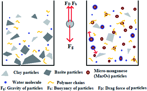
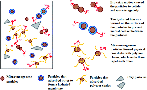
This work aims to study the suspension capacity of barite and micro-manganese (Mn3O4) in different density drilling fluids (1.8–2.8 g cm−3), and to explore the suspension mechanism of Mn3O4. According to the tests of sag performance and rheological properties, the Mn3O4-weighted drilling fluids showed significantly better suspension capacity and rheological properties than that of the barite-weighted drilling fluids at different densities. The suspension mechanism of Mn3O4 was proposed by studying the microstructure and surface properties of Mn3O4 and barite. As shown in Fig. 1, particles are subjected to gravity, buoyancy and drag force in solution. When gravity plays a major role, the particles will sag to the bottom of the container. Barite was more susceptible to sag due to its large particle size and sharp shape. On the contrary, Mn3O4 had a uniform spherical shape and a particle diameter of less than 1 μm, which resulted in intense Brownian motion of the particles. The strong adsorbability by the large specific surface area allowed the micro-manganese particles to interact with each molecule in the solution, and thus exhibited superior suspension property than that of barite.
2. Experimental
2.1 Materials
Brown-red micro-manganese (Mn3O4) with density of 4.8 g cm−3 was provided by Great Technology Co., Ltd. Barite, which is mainly composed of BaSO4, with a density of 4.2 g cm−3 met the API standards. The standard bentonite was obtained from England (IMERYS) and other drilling fluid treatment agents such as DS-301, ammonium salt, potassium humate (KHm), sodium carbonate (Na2CO3), sodium hydroxide (NaOH), potassium polyacrylamide (K-PAM), polymer fluid loss additive (RHPT-2), inhibitor (DS-302), sulfonated brown coal (SMC), brown coal resin (SPNH), emulsified paraffin (RHJ-1) and lubricant (JM-1) used in this study were all supplied by a domestic oil addictive company.2.2 Fluid preparation
The base slurry was prepared by mixing 15 g of bentonite and 2.5 g of anhydrous sodium carbonate with 1000 cm3 of distilled water. The suspension was stirred quickly for 20 min, and then stirred at a low speed and aged for 24 h at room temperature. Then, 0.2 wt% of DS-301 as a coating agent, 0.5 wt% of ammonium salt as an inhibitor and 3 wt% of potassium humate as a fluid loss agent were slowly poured into a certain amount of the base slurry while stirring to prepare water-based drilling fluids (WDFs). Finally, the WDF was weighted to a fixed density (1.8 g cm−3, 2.0 g cm−3, 2.2 g cm−3, 2.4 g cm−3, 2.6 g cm−3, and 2.8 g cm−3) using barite and micro-manganese (Mn3O4) as weighting materials, and formulated into barite/WDFs and Mn3O4/WDFs, respectively.2.3 Sag stability property evaluation
2.4 Rheology and filtration tests
After preparing the barite/WDFs and Mn3O4/WDFs, a MOD.1103 six-speed rotating viscometer (Qingdao Chuangmeng Instrument Technology Services Ltd., China) was used for the rheology measurements. The liquid was poured into the sample cup up to the marked line and the readings from 600 rpm to 3 rpm recorded, which were used to calculate the rheological parameters, such as the apparent viscosity (AV), plastic viscosity (PV) and yield point (YP). The 3 rpm reading after 10 s and 10 min was recorded as the gel strength of the drilling fluid. The rheological parameters were calculated from the value of ∅600 (reading of viscosity at 600 rpm) and ∅300 (reading of viscosity at 300 rpm) using the following formulas:| Apparent viscosity (AV) = 0.5 ∅600 (mPa s) | (3) |
| Plastic viscosity (PV) = ∅600 − ∅300 (mPa s) | (4) |
| Yield point (YP) = 0.5(2∅300 − ∅600) (Pa) | (5) |
The API filtration volume of the drilling fluid was determined with an MOD.SD6A medium-pressure filtration apparatus (Qingdao Haitongda Dedicated Instrument Factory, China). At room temperature, 300 mL drilling fluid was poured into filtration tanks and the filtration volume was measured within 30 min after passing through a filter paper with a diameter of 9 cm at a pressure of 0.69 MPa. Then the drilling fluid was poured into an aging tank and hot rolled at a specific temperature (80 °C, 120 °C, and 150 °C) in a GW300-type variable frequency rolling furnace (Qingdao Tongchun Machinery Factory, China). The rolling time was fixed at 16 h. Rheology and filtration tests were performed before and after the thermal aging experiments.
2.5 Characterization of filter cakes deposited from barite/WDFs and Mn3O4/WDFs
The filter cakes of barite and Mn3O4 were characterized using scanning electron microscopy (SEM, JSM7401, JEOL, Japan). After each filtration test was completed, the filter cakes were flushed to remove the false filter cake with deionized water and the thickness of the fresh filter cake was also measured. Then, the filter cakes were dried, and the cross section of the filter cake was metal sprayed as an observation surface. The permeability (K) of a fresh filter cake was calculated according to Darcy's law:| K = QμL/(AΔpt) | (6) |
2.6 Characterization of API barite and micro-manganese (Mn3O4)
| F = T × f/100 | (7) |
3. Results and discussions
3.1 Property of sag stability
3.2 Rheological properties
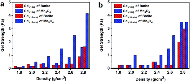 | ||
| Fig. 8 Gel strength of different density barite/WDFs and Mn3O4/WDFs. (a) Before aging and (b) after aging at 120 °C. | ||
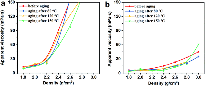
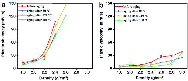
Thus, the above rheological property test indicates that the use of Mn3O4 in drilling fluid can effectively control the viscosity of the drilling fluid and increase the gel strength. However, barite cannot be used to make drilling fluid with a density greater than 2.4 g cm−3. After the density of the barite/WDF exceeded 2.2 g cm−3, its rheological properties began to deteriorate rapidly and severely, after the density reached 2.4 g cm−3, and the basic performance requirements of the drilling fluid could not be satisfied.
3.3 Filtration properties
The fluid loss and well building property refer to the free water in the drilling fluid entering the formation, and the solid phase particles in the drilling fluid adhering to the well to form a filter cake during the filtration process.5 A too large filtrate volume will result in swelling and collapsing of the rock, which is water sensitive, and a thick filter cake will lead to accidents such as tight holes and stuck pipes. The API recommended value is 3 to 15 mL.40 The filtration volume of the barite/WDFs and Mn3O4/WDFs is shown in Fig. 9. With an increased in density, the filtration volume of the barite/WDFs and Mn3O4/WDFs increased slowly. There were slight changes in the filtration volume of the barite/WDFs at different aging temperatures (Fig. 9a). The biggest filtration volume in all the barite/WDFs was 15 mL, which is acceptable with the API standard. However, the filtration volume of the Mn3O4/WDFs was about two times that of the barite/WDFs (Fig. 9b). The filtration volume increased obviously after the aging experiments. After aging at 150 °C, the filtration volume of the Mn3O4/WDFs with densities ranging from 1.8 to 2.8 g cm−3 increased from 9.7, 13.5, 15.5, 17, 17.1, and 19 mL before aging to 18.6, 20, 22, 20, 20.2, and 30 mL, respectively. Obviously, as the amount of Mn3O4 increased, the filtration volume of the Mn3O4/WDFs gradually increased. According to Darcy's law, the filtration volume of unit time is directly related to the permeability and the thickness of the filter cake and the viscosity of the fluid. Thus, one of the keys to minimize the fluid loss in drilling fluids is to improve the quality of the filter cake. In engineering, it is generally required to obtain a thin and tight filter cake, that is, a filter cake with low permeability and small thickness. Subsequently, the characteristics of the filter cakes were considered.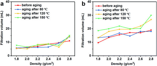 | ||
| Fig. 9 Filtration volume of the drilling fluid with different densities at different aging temperatures. (a) Barite/WDFs and (b) Mn3O4/WDFs. | ||
The fresh filter cakes of the barite/WDFs and Mn3O4/WDFs with a density of 2.2 g cm−3 are shown in Fig. 10. It can be seen that the filter cake of the barite/WDFs was thicker and that of the Mn3O4/WDFs was thinner. According to statistics, the average thickness of the filter cake of the different density barite/WDFs was about 8 mm, while that of Mn3O4/WDFs was only 1.5 mm. However, only observing the surface of the filter cake cannot be used for the direct comparison of the differences in compactness of the filter cakes. Under the pressure of the API filtrate test, the particles in the tested fluid sagged on the filter paper and then formed a filter cake. The inter-filling of the small particles with the large particles reduces the water passage of the filter cake. It is well known that the less cracks in the filter cake, the smaller the permeability of the filter cake. The difference in the formation of filter cake between the barite and Mn3O4 particles can be clearly seen in Fig. 11. Since the barite sagged quickly in the drilling fluid, a large amount of barite was continuously deposited on the filter cake, resulting in the ultimate formation of a thick cake. The sharp and uneven shape of the particles caused the accumulation of particles not to be compact and there were many cracks between the particles (Fig. 11a). However, the Mn3O4 particles had a slow sag rate and good suspension performance in the drilling fluid. Therefore, after a small portion of the particles formed a filter cake, the remaining particles were still suspended in the drilling fluid, and thus the final filter cake was thin. Simultaneously, the spherical and uniform-sized Mn3O4 particles were more densely packed with each other, and there were few cracks between the particles (Fig. 11b). The above filter cake formation analysis was further confirmed by SEM. Fig. 12 shows the microstructures of the dried filter cakes in Fig. 10. As shown in Fig. 12a, the barite was loosely packed, and obvious pores and cracks of about 10 μm can be seen, which are favorable for the penetration of the filtrate. However, the filter cake formed by Mn3O4 was significantly denser. The filter cake magnified 5000 times in Fig. 12b2 was made up of many layers of fine Mn3O4 particles, and no pores and cracks larger than that in the filter cake of the barite/WDFs were found. This indicates that Mn3O4 can form a much denser filter cake than barite. To further verify this conclusion, the permeability (K) of the filter cakes of the barite/WDFs and Mn3O4/WDFs with different densities was calculated according to Darcy's law, the results are shown in Fig. 13. It was proven that the filter cake formed by barite had a permeability greater than that of Mn3O4. Moreover, as the density increased, the filter cake permeability of the barite/WDFs increased rapidly. Under a high density of 2.6 g cm−3, the permeability of the barite/WDFs filter cake was almost six times larger than that of Mn3O4. The same phenomena were observed in the filter cake of the drilling fluid after aging (Fig. 13b). Both the SEM micrographs and the calculated permeability confirmed that the quality of the filter cake formed by Mn3O4 was better than that of barite.
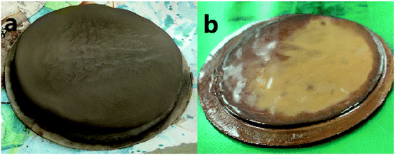 | ||
| Fig. 10 Fresh filter cakes of drilling fluid with a density of 2.2 g cm−3. (a) Barite/WDFs and (b) Mn3O4/WDFs. | ||
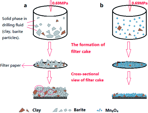 | ||
| Fig. 11 Schematic diagram of the particle packing in the filter cake. (a) Barite/WDFs and (b) Mn3O4/WDFs. | ||
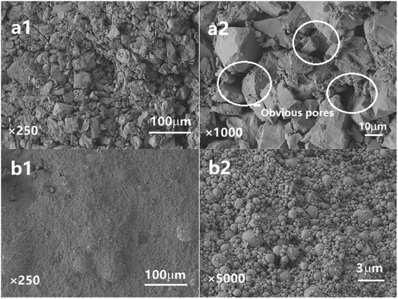 | ||
| Fig. 12 SEM micrographs of the dried filter cakes in Fig. 10. (a1) Filter cake of barite/WDFs magnified by 250 times, (a2) filter cake of the barite/WDFs magnified by 100 times, (b1) filter cake of the Mn3O4/WDFs magnified by 250 times and (b2) filter cake of Mn3O4/WDFs magnified by 5000 times. | ||
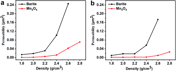 | ||
| Fig. 13 Permeability of the drilling fluid filter cakes with different densities. (a) Before aging and (b) after aging at 80 °C. | ||
However, this conclusion is contrary to the results of the fluid loss test. Why was the filtration volume of the barite/WDFs significantly lower than that of the Mn3O4/WDFs? According to previous studies, the filtration performance of drilling fluids is primarily affected by the viscosity of the drilling fluid and the characteristics of the filter cake.41,42 High viscosity and low filter cake permeability help to decelerate the filtration rate and reduce the filtrate volume.43 In the barite/WDFs, the viscosity increased rapidly with an increase in drilling fluid density, which is the main reason for its improved filtration performance. The increase in viscosity significantly reduced the filtration rate, while the increase in permeability accelerated the filtration rate, which both cancelled each other out. In the barite/WDFs, the effect of viscosity was greater than the effect of permeability, and simultaneously, the sag of barite formed an extremely thick filter cake, thus the filtrate volume of barite/WDFs was low. However, in the Mn3O4/WDFs, the improvement of the filtration performance of the permeability was not enough to offset the influence of other factors, so the filtrate volume was higher than the barite/WDFs. However, the thick filter cake of the barite/WDFs may lead to drilling accidents such as stuck pipes and pumping difficulties, which are not desirable in engineering practice.
To investigate the availability of Mn3O4 in the actual drilling process, the sulfonation drilling fluid system (Table 1) commonly used in drilling sites was used to evaluate the rheology and fluid loss of the drilling fluid after it was weighted by Mn3O4. The performance of the Mn3O4-weighted drilling fluid before and after aging at 150 °C is shown in Tables 2 and 3. It can be seen from Tables 2 and 3 that the Mn3O4-weighted drilling fluid effectively improved the apparent viscosity, yield point and gel strength of the drilling fluid, both before and after aging, which indicates that the suspension and carrying capacity of the drilling fluid were enhanced. For the fluid loss performance, the fluid loss of the drilling fluid after it was weighted by Mn3O4 increased from 4.6 to 8 mL before aging and from 4.8 to 8.2 mL after aging at 150 °C. Although it increased slightly, it was still in the field available range. Therefore, Mn3O4 is fully suitable for use in on-site drilling fluid systems.
| Product | Function | Non-weighted (SG = 1 g cm−3) | Weighted (SG = 2.4 g cm−3) |
|---|---|---|---|
| Water | Base liquid | 384 mL | 384 mL |
| Bentonite | Viscosifier & filtration control | 16 g | 16 g |
| Na2CO3 | Dispersed bentonite | 1 g | 1 g |
| NaOH | Adjust mud pH | 0.8 g | 0.8 g |
| K-PAM | Flocculant | 1.6 g | 1.6 g |
| RHPT-2 | Polymer fluid loss additive | 0.4 g | 0.4 g |
| DS-302 | Viscosity reducer | 2 g | 2 g |
| RHJ-1 | Plugging agent | 10 g | 10 g |
| SMC | Fluid loss additive | 12 g | 12 g |
| SPNH | Fluid loss additive | 12 g | 12 g |
| KHm | Fluid loss additive | 6 g | 6 g |
| JM-1 | Lubricant | 6 g | 6 g |
| Mn3O4 | Adjust mud density | — | 1120 g |
| AV (mPa s) | PV (mPa s) | YP (Pa) | Gel(10 s) (Pa) | Gel(10 min) (Pa) | FLAPI (mL) | |
|---|---|---|---|---|---|---|
| Non-weighted | 14.5 | 10 | 4.5 | 1 | 3 | 4.6 |
| Weighted | 49.5 | 36 | 13.5 | 11 | 16 | 8 |
| AV (mPa s) | PV (mPa s) | YP (Pa) | Gel(10 s) | Gel(10 min) | FLAPI | |
|---|---|---|---|---|---|---|
| Non-weighted | 10.5 | 6 | 4.5 | 1 | 5 | 4.8 |
| Weighted | 38.5 | 32 | 6.5 | 5 | 7 | 8.2 |
3.4 Suspension mechanism analysis
| Elemental composition | Content (wt%) | |
|---|---|---|
| Barite | O | 78.1 |
| S | 14.14 | |
| Ba | 7.76 | |
| Micro-manganese (Mn3O4) | O | 66.48 |
| Mn | 32.95 | |
| Pb | 0.57 |
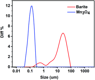
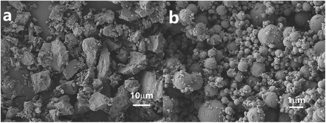
The particle size distribution of barite and Mn3O4 is presented in Fig. 14. The average particle size of the powder is usually represented by d (0.5), which is actually the median diameter. It can be seen in Fig. 14 that the particle size of Mn3O4 was significantly lower than that of barite. The d (0.5) of Mn3O4 and barite was 0.112 μm, 18.309 μm, respectively. Furthermore, the particle size distribution of Mn3O4 was also narrower than that of barite. The micromorphology of barite and Mn3O4 was also very different (Fig. 15). Barite had irregular massive particles with sharp edges, but Mn3O4 contained regular spherical particles with no corners. Consequently, Mn3O4 consisted of spherical particles having an average particle diameter of only 0.1 μm, and barite consisted of massive particles having a sharp angular shape, and its average particle diameter was about 160 times that of Mn3O4. Therefore, Brownian motion of the Mn3O4 particles was dominant in solution, which can improve the dispersion stability of drilling fluids.44
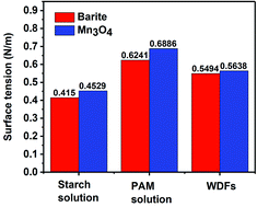
The specific surface area of barite and Mn3O4 was also obtained simultaneously by particle size analysis. Mn3O4 had a large specific surface area of 61.9 m2 g−1, which was almost 40 times that of barite of only 1.64 m2 g−1 (Fig. 17a). A large specific surface area represents a high surface free energy. This caused Mn3O4 to have a strong adsorption effect. In drilling fluid, Mn3O4 not only adsorbs dispersant molecules quickly, thus forming a solvation film on the surface of the Mn3O4 particles, but also forms physical crosslinks with drilling fluid additives such as polymer chains. Thus, the Mn3O4 particles had strong interaction with other molecules, which was proven by the surface tension test. Thereby, the dispersibility and suspension stability of the Mn3O4 particles in the drilling fluid improved. In contrast, barite had a small specific surface area, but a large particle size, so the adsorption between barite particles and other molecules in the drilling fluid was small. The larger self-weight accelerated its sag, which caused the poor suspension stability of the entire drilling fluid system. The zeta potential evaluation further demonstrated that Mn3O4 has better suspension stability in water than barite. The zeta potential results in water with different pH are shown in Fig. 17b. The higher the absolute value of the zeta potential, the more stable the solution system. Alkaline water-based drilling fluids help to increase the degree of hydration of clay. Thus, it is important to increase the suspension stability of the material under alkaline conditions. As presented in Fig. 17b, the zeta potential of the barite solution was 0.732 mV when the pH value was 7, while that of Mn3O4 was −19.9 mV. When the pH value increased from 7 to 8 and 9, the zeta potential of the barite solution was reversed from 0.732 mV to −8.82 mV and −18.5 mV, respectively. Simultaneously, the zeta potential value of the Mn3O4 solution also increased from −19.9 mV to −23.2 mV and −26.2 mV, respectively. It was obvious that the absolute zeta potential value of the Mn3O4 solution was always higher than that of barite, which indicates that the Mn3O4 particles were more electronegative in solution and had higher surface activity, and thus showed higher suspension stability.
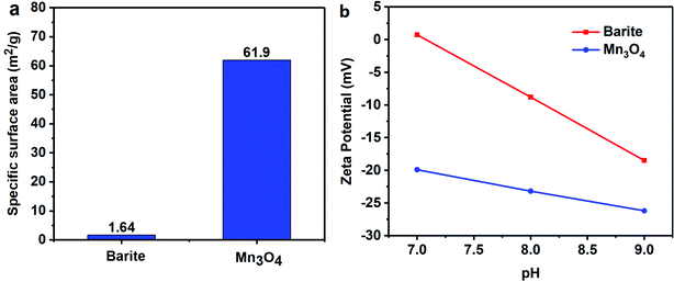 | ||
| Fig. 17 (a) Specific surface area of barite and Mn3O4 and (b) zeta potential of barite and Mn3O4 in distilled water with different pH. | ||
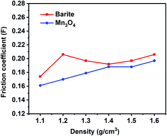
The lubrication performance of drilling fluids has a great influence on the drilling process. High lubricity is beneficial to reduce the friction between the drill string and the well wall, reduce the torque of the rotating drill string, and ensure the smooth operation of the drilling operation. It can be seen in Fig. 18 that the friction coefficient of the Mn3O4/WDFs was lower than that of barite, which demonstrated the better lubrication performance of Mn3O4. The excellent lubricity is also attributed to the small and rounded morphology of the Mn3O4 particles. The spherical shape contributed to the sliding between the particles, which reduced the friction between the particles compared to the sharp bulk of barite.
4. Conclusion
In this study, the effect of micro-manganese (Mn3O4) and barite in drilling fluid was compared, and the sag stability of the weighting materials and the effect on the rheological properties of the drilling fluid were considered. Understanding the suspension mechanism is a prerequisite for improving the sag stability of weighting materials in drilling fluids. The suspension mechanism of Mn3O4 in the drilling fluid was also discussed.The main conclusions of this study are as follows:
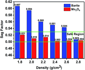
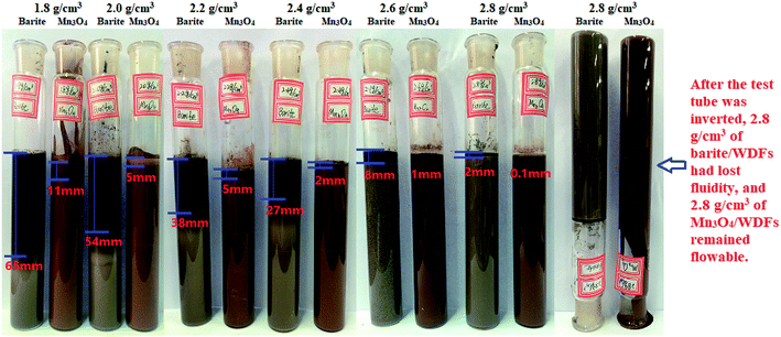
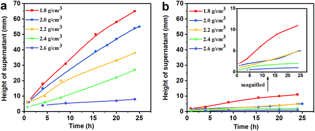
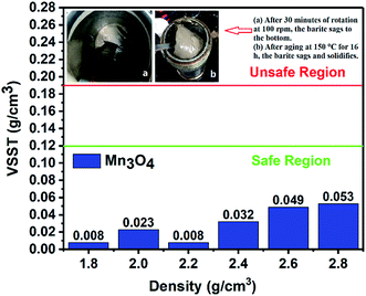
(1) The results of the static sag and dynamic sag experiments showed that Mn3O4 has much better suspension stability in drilling fluid than barite. The static sag and dynamic sag coefficients of Mn3O4/WDFs can be kept within safe limits in the range of drilling fluid densities of 1.8 to 2.8 g cm−3, while that of the barite/WDFs were much higher that the safe range.
(2) Mn3O4 could also improve the rheology of the drilling fluids. The Mn3O4/WDFs could maintain reasonable viscosity and a much higher gel strength even at a density of 2.8 g cm−3.
(3) In the barite/WDF, the viscosity increased rapidly with an increase in drilling fluid density, which is the main reason for the improvement in its filtration performance. However, a thick filter cake was formed due to the severe sag of barite. In the Mn3O4/WDFs, the positive impact of reduced permeability on filtration rate was not sufficient to offset the adverse effects of other factors, and thus the filtrate volume was higher than that of the barite/WDFs.
(4) A uniform spherical structure of less than 1 μm reduced the friction of the Mn3O4 particles in the drilling fluid, which not only slowed down the increase in the AV of the Mn3O4/WDFs with an increase in density, but also reduced the friction coefficient of the Mn3O4/WDF.
(5) The specific surface area of the Mn3O4 particles was much higher than that of barite, resulting in the strong adsorption of the Mn3O4 particles on water molecules and polymers in the drilling fluid. The formation of a hydration film and physical crosslinking with polymer chains prevented sagging caused by the adsorption of small particles to form large particles.
The study of the suspension mechanism illustrates the reason why Mn3O4 improved the suspension capacity of the drilling fluids, and provides a basis for better the application of Mn3O4 in drilling fluids and further improving the sag stability of barite in drilling fluids.
Conflicts of interest
There are no conflicts to declare.Acknowledgements
We would like to thank for the financial support from Natural Nature Science Foundation of China (J218076), national Key R&D Program of china (2016YFE0202200 and PY201802) for this work.References
- T. H. Omland, A. Saasen, C. Van Der Zwaag and P. A. Amundsen, presented in part at the Asia Pacific Oil and Gas Conference and Exhibition, Jakarta, Indonesia, 30 October–1 November, 2007 Search PubMed.
- M. Amighi and K. Shahbazi, presented in part at the SPE Deep Gas Conference and Exhibition, Manama, Bahrain, 24–26 January, 2010 Search PubMed.
- S. Elkatatny, Energies, 2018, 11 Search PubMed.
- K. Bybee, J. Pet. Technol., 2004, 56, 62–63 Search PubMed.
- K. A. Fattah and A. Lashin, J. Afr. Earth Sci., 2016, 117, 345–357 CrossRef CAS.
- P. A. Bern, M. Zamora, K. S. Slater and P. J. Hearn, presented in part at the SPE Annual Technical Conference and Exhibition, Denver, Colorado, 6–9 October, 1996 Search PubMed.
- M. R. Amighi and K. Shahbazi, Pet. Sci. Technol., 2011, 29, 1864–1872 CrossRef CAS.
- P. A. Bern, E. van Oort, B. Neustadt, H. Ebeltoft, C. Zurdo, M. Zamora and K. S. Slater, SPE Drill. Completion, 2000, 15, 25–30 CrossRef.
- T. Nguyen, S. Miska, M. Yu, N. Takach, R. Ahmed, A. Saasen, T. H. Omland and J. Maxey, J. Pet. Sci. Eng., 2011, 78, 160–165 CrossRef CAS.
- W. Dye, T. Hemphill, W. Gusler and G. Mullen, SPE Drill. Completion, 2001, 16, 27–34 CrossRef.
- A. Naderi and K. Shahbazi, Pet. Sci. Technol., 2014, 32, 84–90 CrossRef CAS.
- P. Xu, M. Xu, Z. Tao, Z. Wang and T. Huang, R. Soc. Open Sci., 2018, 5, 180358 CrossRef.
- W. Muller and M. Karad, Oil Gas Eur. Mag., 2009, 35, 117–120 Search PubMed.
- M. R. Gregoire, M. H. Hodder, S. Peng and J. Massam, presented in part at the SPE/IADC Drilling Conference and Exhibition, Amsterdam, The Netherlands, 17–19 March, 2009 Search PubMed.
- G. Quercia, R. Belisario and R. Rengifo, Wear, 2009, 266, 1229–1236 CrossRef CAS.
- B. Mohamed and A. Ebrahim, in Advances in Biology, Bioengineering and Environment, ed. N. Mastorakis, V. Mladenov, M. Demiralp and A. Bojkovic, World Scientific and Engineering Acad and Soc, Athens, 2010, pp. 114–118 Search PubMed.
- A. Gadalla, R. Pino, P. Ezi, N. Zayer, M. Al Hudaithi, A. Addagalla, B. Kosandar, P. Jadhav, I. Lawal, A. Imran and O. Hassan, presented in part at the SPE Middle East Oil & Gas Show and Conference, Manama, Kingdom of Bahrain, 6-9 March, 2017 Search PubMed.
- N. E. Blomberg and B. Melberg, J. Pet. Technol., 1984, 36, 969–974 CrossRef.
- K. Bybee, J. Pet. Technol., 2008, 60, 81–82 Search PubMed.
- S. M. Zhou, G. S. Li and Q. C. Wang, Pet. Explor. Dev., 2013, 40, 115–118 CrossRef.
- A. S. Al-Yami and H. A. Nasr-El-Din, presented in part at the SPE Annual Technical Conference and Exhibition, Anaheim, California, U.S.A., 11–14 November, 2007 Search PubMed.
- C. Steele, W. L. Hart and D. Oakley, presented in part at the Offshore Mediterranean Conference and Exhibition, Ravenna, Italy, 11–14 March, 2007 Search PubMed.
- A. S. Al-Yami, H. A. Nasr-El-Din, M. A. Al-Shafei and M. A. Bataweel, presented in part at the SPE Eastern Regional/AAPG Eastern Section Joint Meeting, Pittsburgh, Pennsylvania, USA, 11–15 October, 2008a Search PubMed.
- A. S. Al-Yami, H. A. Nasr-El-Din, M. A. Bataweel, A. A. Al-Majed and H. Menouar, presented in part at the SPE International Symposium and Exhibition on Formation Damage Control, Lafayette, Louisiana, USA, 13–15 February, 2008b Search PubMed.
- V. Wagle, A. S. Al-Yami, Z. AlAbdullatif, A. S. Bubshait and A. AlSafran, presented in part at the SPE North Africa Technical Conference and Exhibition, Cairo, Egypt, 14–16 September, 2015 Search PubMed.
- K. van Netten, J. Zhou, K. P. Galvin and R. Moreno-Atanasio, Chem. Eng. Sci., 2013, 93, 229–237 CrossRef CAS.
- N. M. Kovalchuk and V. M. Starov, Adv. Colloid Interface Sci., 2012, 179–182, 99–106 CrossRef CAS.
- A. M. Al Moajil, A. I. Rabie, H. A. Nasr-El-Din, M. Al-Bagoury and C. D. Steele, presented in part at the Offshore Technology Conference Asia, Kuala Lumpur, Malaysia, 22–25 March, 2016 Search PubMed.
- Z. A. Alabdullatif, A. S. Al-Yami, V. B. Wagle, A. S. Bubshait and A. M. Al-Safran, presented in part at the Abu Dhabi International Petroleum Exhibition and Conference, Abu Dhabi, UAE, 10–13 November, 2014 Search PubMed.
- Y. Kar, A. M. Al-Moajil, H. A. Nasr-El-Din, M. Al-bagoury and C. D. Steele, presented in part at the SPE Middle East Oil and Gas Show and Conference, Manama, Bahrain, 25-28 September, 2011 Search PubMed.
- A. Rehman, A. M. Al Moajil, H. A. Nasr-El-Din, M. Al-bagoury and C. D. Steele, presented in part at the SPE Latin America and Caribbean Petroleum Engineering Conference, Mexico City, Mexico, 16–18 April, 2012 Search PubMed.
- A. M. Al Moajil, H. A. Nasr-El-Din, Y. Kar, M. Al-Bagoury and C. D. Steele, presented in part at the Abu Dhabi International Petroleum Exhibition and Conference, Abu Dhabi, UAE, 9–12 November, 2015 Search PubMed.
- G. Chern, L. Horng, M. Z. Lin, S. M. Li, D. S. Lee, T. Y. Hou, M. F. Tai and T. H. Wu, J. Magn. Magn. Mater., 2000, 209, 138–141 CrossRef CAS.
- A. M. Al Moajil and H. A. Nasr-El-Din, J. Can. Pet. Technol., 2013, 52, 64–74 CrossRef.
- A. M. Al Moajil, H. A. Nasr-El-Din, A. S. Al-Yami, A. D. Al-Aamri and A. K. Al-Agil, presented in part at the SPE International Symposium and Exhibition on Formation Damage Control, Lafayette, Louisiana, USA, 13–15 February, 2008 Search PubMed.
- A. M. Al Moajil and H. A. Nasr-El-Din, J. Can. Pet. Technol., 2014, 53, 122–130 CrossRef.
- J. Maxey, presented in part at the Nordic Rheology Conference, Stavanger, Norway, June, 2007 Search PubMed.
- A. E. Bayat, P. J. Moghanloo, A. Piroozian and R. Rafati, Colloids Surf., A, 2018, 555, 256–263 CrossRef CAS.
- V. Wagle, A. S. Al-Yami, M. Aljubran and H. Al-Bahrani, presented in part at the SPE Kingdom of Saudi Arabia Annual Technical Symposium and Exhibition, Dammam, Saudi Arabia, 8/16/2018 Search PubMed.
- M.-C. Li, Q. Wu, K. Song, C. F. De Hoop, S. Lee, Y. Qing and Y. Wu, Ind. Eng. Chem. Res., 2016, 55, 133–143 CrossRef CAS.
- K. Elshreef, J. Pet. Environ. Biotechnol., 2013, 4, 1000157 Search PubMed.
- L. Yan, C. Wang, B. Xu, J. Sun, W. Yue and Z. Yang, Mater. Lett., 2013, 105, 232–235 CrossRef CAS.
- D. Buelichen and J. Plank, J. Appl. Polym. Sci., 2012, 124, 2340–2347 CrossRef CAS.
- D. Wen, G. Lin, S. Vafaei and K. Zhang, Particuology, 2009, 7, 141–150 CrossRef CAS.
| This journal is © The Royal Society of Chemistry 2019 |

