 Open Access Article
A facile approach to prepare crosslinked polysulfone-based anion exchange membranes with enhanced alkali resistance and dimensional stability
Chao Wanga,
Nengxiu Pana,
Yuliang Jianga,
Junbin Liaoa,
Arcadio Sottob,
Huimin Ruana,
Congjie Gaoa and
Jiangnan Shen *a
*a
aCenter for Membrane Separation and Water Science & Technology, Zhejiang University of Technology, Hangzhou 310014, China. E-mail: shenjn@zjut.edu.cn
bRey Juan Carlos University, Fuenlabrada, Camino del Molino, s/n, Madrid, 28942, Spain
First published on 8th November 2019
Abstract
Novel anion exchange membranes with enhanced ion exchange capacity, dimensional stability and alkali stability were prepared by a facile synthesis method. Internal crosslinking networks in the resulting membranes were achieved by reacting chloromethylated polysulfone with 4,4′-trimethylene bis(1-methylpiperidine) (BMP), where BMP was used as both a quaternization reagent and crosslinker without requirement of post-functionalization. In order to evaluate the alkali resistance and dimension stability performance of the resulting membranes, the molar ratio of BMP in the resulting membranes was fixed at four different contents: 40%, 60%, 80% and 100%. The obtained membranes were accordingly denoted as CAPSF-N, in which N = 40, 60, 80 and 100, respectively. Due to the dense internal network structure and spatial conformation of the six-membered rings, the resulting CAPSF-N AEMs showed enhanced dimensional structures (at 60 °C, the water uptakes and swelling ratios of CAPSF-N were 8.42% to 14.84% and 2.32% to 5.93%, respectively, whereas those for the commercial AEM Neosepta AMX were 44.23% and 4.22%, respectively). In addition, after soaking in 1 M KOH solution at 60 °C for 15 days, the modified membranes exhibited excellent alkaline stability. The CAPSF-100 membrane showed the highest alkali stability (retained 85% of its original ion exchange capacity and 84% of its original OH− conduction after the alkaline stability test), whereas the non-crosslinked APSF broke into pieces. Additionally, compared to the commercial Neosepta AMX membrane under the same test conditions, the desalination efficiency of CAPSF-100 was enhanced, and the energy consumption was lower.
1 Introduction
Electrodialysis (ED) is a combination of an electrochemical process and a dialysis diffusion process. The ED process exhibits several operational advantages in terms of energy saving, environmental protection, and simple operation. It has been widely used in desalination and industrial production.1,2 For example, ED has been applied in demineralization of salt solution, desalination and reuse of sewage or industrial wastewater, and preparation of acids and bases by bipolar membrane ED from salt solution. The ion exchange membrane (IEM), as the core part of the ED, has the function of selecting specific ions to pass through. Cation exchange membranes (CEMs) and anion exchange membranes (AEMs) are two major types of IEMs which depend on the opposite charge of the fixed groups.3 Driven by the external direct current field, anions are induced to move to the anode by AEMs, and cations are induced to move to the cathode through cation exchange membranes. According to the mechanism of the IEMs and their different environments, it is necessary to adjust the design of the substrate, the functional group types, and the polymer structures of these membranes.Recently, the application of AEMs has become widespread, such as fuel cells,4–6 selective separation of different anions by electrodialysis7–10 and high pollution environments.11,12 For different applications of AEMs, they require high ion exchange capacity (IEC), low membrane surface resistance (R), low water uptake (WU), strong dimensional stability, strong physical and chemical stability, and strong alkali resistance. Theoretically, a high IEC value means that more active sites can be used for ion exchange in the membrane structure so as to ensure the full migration of ions.13,14 However, this will usually lead to excessive swelling of the membrane, and a “trade-off” phenomenon exists between WU and IEC.15 Dimensional stability and IEC are the key parameters for AEM performance. The existence of this “trade-off” limits the development of IEMs.
Alkali resistance is another important property that determines the overall performance of AEMs.2,16,17 Inevitably, in complex chemical processes, practical applications in industrial wastewater treatment processes, and even in the process of membrane cleaning, the chemical environment will be complex and contain corrosive substances, such as alkaline species. Therefore, it is required that the membrane is resistant to basic substances. The lack of a simple and controllable method to achieve both good alkali stability and high ionic conductivity of AEMs hinders the widespread application of alkali-resistant AEMs. Due to the attack of hydroxide ions, the quaternary ammonium groups of AEMs follow two major degradation pathways:2,18 (1) Hofmann elimination and (2) nucleophilic substitution. OH− attacks the nitrogen atom containing hydrogen atoms at the β position, and the quaternary ammonium group is eliminated; this is called Hofmann elimination. An SN2 nucleophilic substitution reaction3 between OH− and the α-position carbon atom of the ammonium group ultimately produces alcohols and amines; this is called nucleophilic substitution.
In conventional AEMs, different quaternary ammonium cations are densely grafted at the active sites of the backbone (quaternary ammonium AEMs,19,20 guanidine AEMs,21,22 quaternary phosphonium AEMs, imidazole AEMs23); although AEMs can easily achieve a high IEC, the alkaline stability of this type of AEM tends to be poor, and Hofmann degradation and nucleophilic substitution reactions readily occur, leading to decreased ion exchange groups and even membrane rupture.4,18 Zhang et al.23 prepared AEMs with chloromethylated polysulfone and 1-methylimidazole functional groups; although the AEMs exhibited enhanced overall performance, the quaternary ammonium groups densely grafted at the backbone afforded insufficient physical and chemical stability as well as degradation in alkaline environments.
In order to balance the dimensional stability, ionic conductivity and alkaline stability of AEMs, many researchers have focused investigations on this field. Dang et al.5 introduced long flexible hydrophobic side chains with multiple quaternary ammonium groups which had fewer active sites to a polymer; by controlling the hydrophobic chain length and the amount of hydrophilic quaternary ammonium groups, micro-phase separation could be achieved.5,24 With improved alkali resistance, a certain control of water uptake of the membrane was also achieved. Yang et al.25 employed 1-(N′,N′-dimethylamino)-6,12-(N,N,N-trimethylammonium) dodecane bromide as a substance for constructing hyperbranched structures; the ionic conductivity of the resulting AEMs was improved, while the chemical stability was enhanced. Guo et al.26 used a cluster of alkyl branches containing three imidazolium cations with six methylene spacers grafted to fluorenyl poly(aryl ether sulfone) to form internal nanostructures in AEMs via a novel long flexible multi-cation spacer that facilitated ion migration (120 ms cm−1 at 80 °C) and provided superior dimensional stability (12.0%, 30 °C). Although the above methods are helpful for improving dimensional stability, ion conductivity and alkali stability, complicated preparation processes and high preparation costs are involved.
Cross-linking is a simple method for preparing improved dimensionally stable and alkali-resistant AEMs. Particularly, cross-linked AEMs with high IEC values can minimize swelling, increase steric hindrance of degradation in alkaline environments, and decrease the attack of OH− on the polymer backbone or ion exchange groups, thus improving alkali stability.27,28 Cross-linked AEMs can be prepared by various methods, such as a series of end-linked cross-linked AEMs by “click chemistry”,29 reacting halomethylated polymers with diols, dihalides, and diamines,30–34 ring-opening metathesis polymerization (ROMP),35,36 and thermal cross-linking.37,38
Generally, preparation of cross-linked AEMs requires two steps, which are quaternization and cross-linking. Some reactions must performed at high temperature and in other complicated environments; these complicated and time-consuming experimental procedures limit their potential for industrial application. Jiang et al.18 used 1-methylpyrrolidine as a quaternization reagent and 4,4-trimethylenedipiperidine (TMDP) as a crosslinker. The cross-linking agent did not provide any ion exchange sites and formed a complicated three-dimensional network structure that improved both the dimensional and alkali stability of the film; however, the preparation process was complicated and other factors influenced the stability of the preparation process and the AEMs, limiting their industrial application. Komkova et al.31 used N,N,N′,N′-1,2-tetramethylethylenediamine, N,N,N′,N′-tetramethyl-1,4-butanediamine and N,N,N′,N′-tetramethyl-1,6-hexanediamine as both quaternization and cross-linking reagents under mild reaction conditions. In addition, studies have shown that some n-spiral ring quaternary ammonium salts have higher alkali stability; this can be attributed to the spatial conformation limit of the ring, which increases the energy barriers required for SN2 nucleophilic substitution and Hofmann elimination and thus decreases the attack from OH−.39
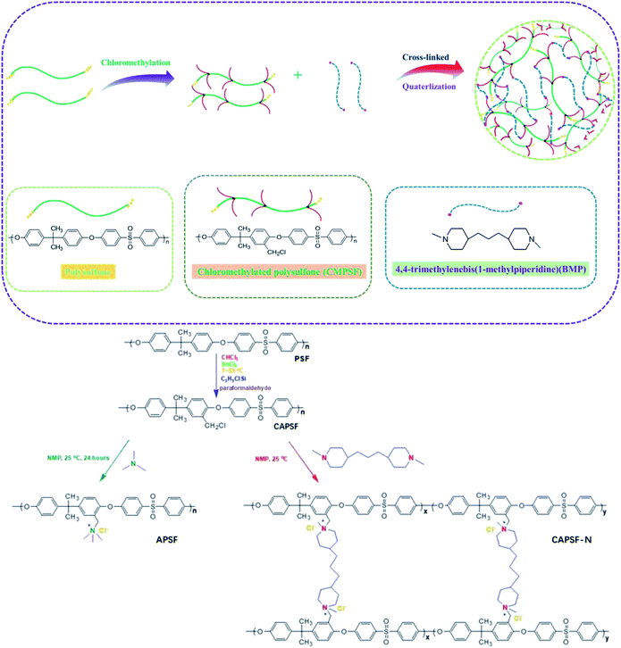
In view of these observations, this work aims to develop AEMs with enhanced dimensional stability, ion-exchange capacity and alkali resistance through a simple procedure. AEMs were fabricated by constructing an internal cross-linked network in the polymer backbone. Chloromethylated polysulfone (CAPSF) was selected as the polymer backbone; it has good physico-chemical stability. CAPSF was synthesized by avoiding the use of the carcinogenic reagent chloromethyl ether.40 4,4′-trimethylene bis(1-methylpiperidine) was selected as the quaternary ammonium and cross-linking agent due to the symmetric structure and ring conformation of the two piperidine rings. By controlling the content of 4,4′-trimethylene bis(1-methylpiperidine) in the casting solution, only one step is required to form the cross-networking structure with chloromethylated polysulfone at room temperature. The IEC, WU, swelling ratio (SR), alkali resistance, mechanical strength and desalination efficiency of the prepared AEMs with several cross-linking degrees were considered.
2 Experimental
2.1 Materials
Polysulfone (Mw ∼ 35![[thin space (1/6-em)]](https://www.rsc.org/images/entities/char_2009.gif) 000 g mol−1) and 4,4′-trimethylene bis(1-methylpiperidine) (99%) were bought from Sigma-Aldrich, China. PSF was dried at 80 °C in vacuum before use. Chloroform (CHCl3), stannic chloride, paraformaldehyde, trimethylchlorosilane, sodium chloride, dimethyl sulfoxide (DMSO), 1-methyl-2-pyrrolidone (NMP), dimethylacetamide (DMAc) and sodium sulfate were obtained from Aladdin, Co. Ltd. (Shanghai, China). The reagents purchased were all analytical reagents and were used directly. Commercial IEMs, Neosepta AMX and CMX were obtained from Fujifilm, Japan.
000 g mol−1) and 4,4′-trimethylene bis(1-methylpiperidine) (99%) were bought from Sigma-Aldrich, China. PSF was dried at 80 °C in vacuum before use. Chloroform (CHCl3), stannic chloride, paraformaldehyde, trimethylchlorosilane, sodium chloride, dimethyl sulfoxide (DMSO), 1-methyl-2-pyrrolidone (NMP), dimethylacetamide (DMAc) and sodium sulfate were obtained from Aladdin, Co. Ltd. (Shanghai, China). The reagents purchased were all analytical reagents and were used directly. Commercial IEMs, Neosepta AMX and CMX were obtained from Fujifilm, Japan.
2.2 Membrane fabrication
2.3 Membrane characterization
 | (1) |
 | (2) |
 | (3) |
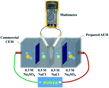
Current–voltage (C–V) tests were used to obtain the ICD values of the membranes. A similar device was used to measure the surface area resistance of the membranes. Current–voltage curves of the prepared AEMs were obtained by recording the gradually increased applied current density (from 0 to 60 mA cm2) and the corresponding voltage change. The intermediate solution and the electrode solution were fed with 0.5 M NaCl solution and 0.3 M Na2SO4 solution, respectively.
According to eqn (4) and (5), WU and SR were calculated:
 | (4) |
 | (5) |
The OH− conductivity of the membranes was determined by an Autolab PGSTAT302N using a 4-probe technique and frequencies in the range of 1 Hz to 1 MHz. All tested membranes (4 cm in length, 1 cm in width) were submerged in 1.0 M KOH aqueous solution and soaked for a day. Before the test, the tested samples were rinsed thoroughly with DI water, and the OH− conductivity (σ) was calculated by the following eqn (6):
 | (6) |
 | (7) |
 | (8) |
 | (9) |
![[thin space (1/6-em)]](https://www.rsc.org/images/entities/char_2009.gif) 485 C mol−1); I represent the applied current, which is 0.45 A; N represents the number of repeating units, which is 1; U is the voltage over the ED device; and Mb is the relative molecular mass of NaCl, Mb(NaCl) = 58.5.
485 C mol−1); I represent the applied current, which is 0.45 A; N represents the number of repeating units, which is 1; U is the voltage over the ED device; and Mb is the relative molecular mass of NaCl, Mb(NaCl) = 58.5.
3 Results and discussion
3.1 1H NMR and FTIR spectra
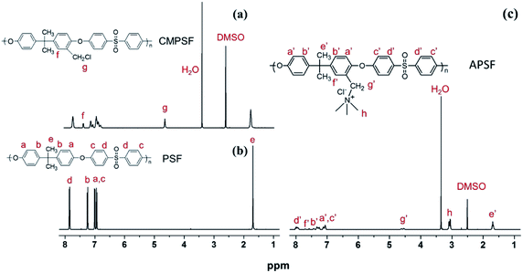
The chloromethylation of polysulfones (PSF) and the reaction of chloromethylated polysulfone and trimethylamine was studied by NMR spectroscopy. In the 1H NMR spectrum of PSF (Fig. 2(b)), the signals with chemical displacements of 6.90 to 7.86 ppm can be attributed to the polyhydrogen (H1) on the phenyl group, while the peaks with chemical displacements of 1.72 ppm can be ascribed to hydrogens (H2, –CH3) on the methyl group. In contrast, in the CAPSF spectrum (Fig. 2(a)), at 4.56 ppm, a new sharp signal appears; the chemical shift is ascribed to the hydrogen chloride (H3, –CH2Cl) hydrogen. These observations confirmed the formation of the –CH2Cl group in CAPSF. The degree of chloromethylation (DC) of CAPSF was estimated to be 127% by means of the relative area ratio of the –CH2Cl and –CH3 peaks, calculated by the equation DC = 3SH3/SH2 (ref. 41,42) (where S represents the integral area of the proton peak). In the APSF 1H NMR spectrum (Fig. 2(c)), in contrast with the 1H NMR spectrum of CAPSF, a new signal appears at 2.98 to 3.15 ppm;43 this can be attributed to the successful reaction of TMA and CAPSF.The insolubility of the prepared CAPSF-N AEMs is due to the cross-linked reaction between 4,4′-trimethylene bis(1-methylpiperidine) (BMP) and CAPSF; it indicates that a crosslinked network was successfully formed.18 By comparing the FT-IR spectra of CAPSF-N and CAPSF, the cross-linked structure was further confirmed.
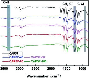
The FT-IR spectra of CAPSF and CAPSF-N18,41 are shown in Fig. 3. Because of the hydrophobic nature of CAPSF,18 it is difficult for CAPSF membranes to absorb water from the external environment. When BMP was successfully introduced, the CAPSF-N membranes obtained hydrophilic performance and absorbed external water, which is reflected in the characteristic peak of the stretching vibration of O–H groups at around 3375 cm−1. With increasing content of BMP (from CAPSF-40 to CAPSF-100), the peak at 3375 cm−1 becomes sharper, which indicates the successful quaternization reaction.
3.2 Measurement of cross-linking degree
Measuring solubility is a facile way to assess the crosslinked structures inside membranes.44,45 As shown in Table 1, the prepared cross-linked AEMs (CAPSF-N) exhibited high mass retention ratios over 80%; also, they dissolved only slightly in NMP, DMAc, DMSO, and CHCl3 after 7 days, suggesting their non-extractable nature. The three-dimensional network structures constructed inside the AEMs endow them with excellent solvent resistance ability. Conversely, the CAPSF membrane exhibited excellent solubility in these solvents and completely dissolved in the solutions.| Membrane | Organic solvents | |||
|---|---|---|---|---|
| NMP | DMAC | DMSO | CHCl3 | |
| CMPSF | 0 | 0 | 0 | 0 |
| CAPSF-40 | 88.3% | 86.7% | 80.6% | 89.7% |
| CAPSF-60 | 95.1% | 85.6% | 94.9% | 97.1% |
| CAPSF-80 | 94.5% | 91.6% | 95.7% | 96.1% |
| CAPSF-100 | 99.2% | 96.9% | 98.9% | 96.8% |
3.3 Physico-chemical properties of different AEMs
As illustrated in Table 2, the prepared AEMs had similar thicknesses (53 to 61 μm) under the same environmental conditions. Thus, we can easily compare the possible variation of other physico-chemical membrane properties as a result of the proposed modifications. BMP was used as both a crosslinker and quaternary ammonium reagent. As the cross-linked degree increases, the IEC shows a consistent upward trend because of the increasing number of ion exchange groups, and the experimental IEC value approaches the theoretical value.| Membrane | IECa mmol g−1 | IECb mmol g−1 | Thickness μm | WUc % | LERd % | ARe Ω cm2 | Transport number |
|---|---|---|---|---|---|---|---|
| a IEC, calculated values (DC is 1.27).b IEC, experimental values by potential titration.c WU, water uptake.d LER, linear expansion ratio.e AR, area resistance. | |||||||
| CAPSF-40 | 0.79 | 0.68 | 53 | 8.42 | 1.42 | 16.31 | 0.91 |
| CAPSF-60 | 1.13 | 1.08 | 57 | 9.51 | 1.53 | 4.23 | 0.93 |
| CAPSF-80 | 1.44 | 1.34 | 55 | 10.63 | 2.25 | 3.74 | 0.96 |
| CAPSF-100 | 1.73 | 1.49 | 56 | 12.36 | 2.75 | 2.41 | 0.98 |
| APSF | 1.56 | 1.47 | 61 | 14.84 | 6.76 | 3.32 | 0.96 |
| Neosepta AMX | — | 2.16 | 115 | 44.23 | 4.22 | 2.51 | 0.98 |
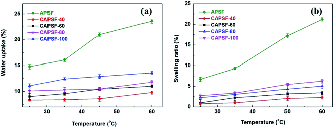
As shown in Fig. 4(a) and (b), the water uptake (WU) is at a low level (8.42% to 14.84%); the enhanced IEC endows the CAPSF-N AEMs with higher WU. Usually, excessive membrane swelling can be effectively suppressed by reinforcing the crosslinked network. In this experiment, the effect of the water absorption ability provided by IEC is probably slightly stronger than the water resistance ability that the internal crosslinked structure provides. Tighter networks and enhanced interactions between adjacent polymer segments increased the resistance of water molecules to entering the cross-linked CAPSF-N AEMs. SR shows the positive correlation of this trend with the water content; with increasing cross-linking degree, the LER increases.
With increasing IEC value, the surface area resistance of the cross-linked AEMs decreases remarkably from 16.31 to 2.41 Ω cm2. This phenomenon arises due to the conductive ion exchange groups produced by the reaction between the BMP groups and the chloromethylated polysulfone backbone. In the same test conditions, the membrane surface area resistance of the CAPSF-100 membrane (2.41 Ω cm2) was lower than that of a commercial membrane (Neosepta AMX, 2.51 Ω cm2). The transport numbers of the cross-linked CAPSF-N AEMs show an increasing trend from 0.91 to 0.98 with N from 40 to 100. The high transport number of CAPSF-100 (0.98) represents higher perm-selectivity, which is caused by its higher IEC as well as its denser interior network. Due to its lower membrane surface area resistance and high transport number, CAPSF-100 is more suitable for practical application in desalination.
3.4 Mechanical properties
Table 3 illustrates the mechanical properties of the cross-linked AEMs (CAPSF-N) and APSF AEM. Eb and Ts are significant factors in the mechanical properties of membranes. The cross-linked CAPSF AEMs show an incremental trend of tensile strength (Ts) from 20.4 MPa to 26.4 MPa. Conversely, the elongation at break (Eb) apparently decreases, from 120.1% to 47.8%; this suggests that the cross-linked network provided compact and stiff internal structures. Generally, the cross-linked CAPSF-100 AEM shows a mechanical strength of 26.4 MPa and an elongation at break of 47.8%. This behavior is due to the favorable balance obtained between high IEC and good mechanical properties. The excellent mechanical stability of the prepared AEMs suggests that they are feasible to use in ED processes.| Property | CAPSF-40 | CAPSF-60 | CAPSF-80 | CAPSF-100 | APSF |
|---|---|---|---|---|---|
| Ts/MPa | 20.4 | 22.1 | 21.0 | 26.4 | 14.3 |
| Eb/% | 120.1 | 84.8 | 60.6 | 47.8 | 173.5 |
3.5 Alkaline stability
It is critical for AEMs to have long-term alkali stability in alkaline environments. The degradation resistance that affects the alkaline stability of AEMs in some complicated operational environments is mainly provided by the functional groups and the polymer backbone. At high temperatures, strongly electrophilic functional groups are more likely to be attacked by OH−.2,46 Thus, the IEC retention ratios and conductivity retention ratios of the cross-linked AEMs (CAPSF-N) and APSF membrane sample were tested to evaluate their alkaline stability by calculating the ratio of IEC and the conductivity of the tested AEMs before and after being soaked in 1 M KOH at 60 °C for 15 days.As illustrated in Fig. 5(a), during the stability test, the CAPSF-N AEMs show high alkaline stability; this is confirmed by the slight decreases of their IEC values. It is worth noting that the non-crosslinked APSF membrane showed poor alkali resistance ability; after immersion in 1 M KOH for 3 days, it started to break into pieces, rendering it useless for further tests. Comparatively, after an initial sharp drop stage, the ion conductivities of the CAPSF-N AEMs exhibited a nearly constant trend. After 15 days, over 70% IRR of the cross-linked CAPSF-N AEMs were retained, and as result of the cross-linked degree increase, the IRR increased. For example, the IRR of CAPSF-100 reached nearly 86%, while CAPSF-40 only retained 72% of its original IEC after the test. As illustrated in Fig. 5(b), the corresponding conductivity retention ratios show an almost consistent trend with the IEC retention ratios, as we predicted.
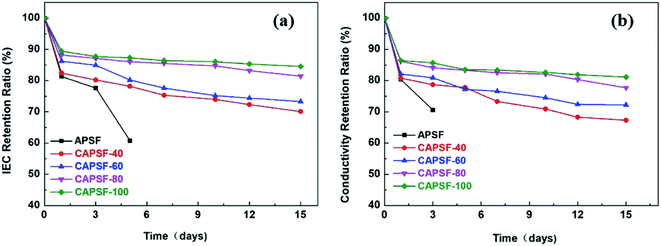 | ||
| Fig. 5 (a) IEC retention ratios and (b) conductivity retention ratios of the tested AEMs, immersion in 1 M KOH at 60 °C for 15 days, respectively. | ||
Because of the attack of OH− anions, the brittle and fragile performance of the non-crosslinked AEM (APSF) is mainly due to the interaction of nucleophilic substitution and the Hofmann degradation mechanism;47 the stable polymer system was broken, resulting in reduction of the ion exchange groups and electrochemical oxidative stress. Although the polysulfone backbone is relatively inexpensive, it has been reported that it shows unstable performance in alkaline environments and is subject to hydrolytic cleavage of the quaternary groups due to the existence of aryl-ether bands in the polysulfone ammonium groups;48 the added BMP readily alleviated this phenomenon, even in 1 M KOH at 60 °C for up to 16 days. On one hand, the densely crosslinked structure inside CMPSF-N increased the energy barriers of the Hofmann elimination and nucleophilic substitution reactions. On another hand, the limitation of the spatial conformation of the six-member ring increases the transition state energy of the substitution reaction and the elimination reaction.49
3.6 Limiting current density (LCD) and desalination performance
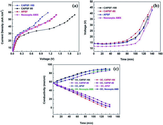
LCD is also a key parameter for electrodialysis. When the operating current density approaches or exceeds the critical state, the concentration polarization phenomenon will occur. At this time, the electrolyte ion concentration on the membrane surface of the desalting chamber is much lower than that of the main solution, and the ion content on the membrane surface of the concentration chamber is much higher than in the main solution; this results in great hazards, such as significantly increased membrane resistance, decreased salt rejection rate, and decreased current efficiency. Therefore, the operating current density must be controlled at an appropriate level. C–V curves were used to investigate the limiting current density during the desalination process. Generally, three typical characteristic regions, (1) the ohmic region, (2) the limiting current region, and (3) the over-limiting region, are displayed in the C–V curves.50,51The cross-linked membranes were tested and, as expected, showed better electrodialysis performance (CAPSF-100, CAPAF-80) compared with APSF and the commercial AEM (Neosepta AMX). As shown in Fig. 6(a), the LCD values of all the membranes are higher than the applied current density (22.94 mA cm−2), which guarantees the normal migration of ions, avoids hydrolysis and leads to additional current consumption for transport of OH−. The LCD of CAPSF-100 is higher than that of the commercial AEM (Neosepta AMX); CAPSF-100 can be feasibly operated at higher current densities with a low area resistance as well as a high LCD.
After a continuous-mode ED test, the change in conductivity of the NaCl solution in the DC and CC and the potential over the device during the test were recorded. As illustrated in Fig. 6(c), the conductivity decreased in the dilute chamber and increased in the concentrate chamber; this is ordinary behavior for ion transport through an ion exchange membrane driven by an electric field. Accordingly, as shown in Fig. 6(b), the potential over the stack with different AEMs increased continuously until the maximum power was reached, due to the decreased number of available ions for migration.
The cross-linked CAPSF-100 showed better desalination performance than commercial AEM (Neosepta AMX) for the 150 min ED test. As shown in Fig. 7(a) and (b), the NaCl removal ratio and current efficiency of cross-linked CAPSF-100 after a 2.5 h ED test were the highest (around 96.7%, 82.3% calculated) among the testing samples. Usually, the IEC, WU, and polymer structure play important roles in the ED performance. The collective effects of high LCD and good dimensional stability may lead to good desalination performance and high current efficiency of the CAPSF-100 AEM. The high dimensional stability of the CAPSF-100 AEM is expected to ensure good mechanical stability and can help maintain a stable desalination process throughout the electrodialysis process. On the other hand, the concentration polarization generated by the electrodialysis process also affects the transport and conduction of conductive ions at the interface and inside of the membrane. The low energy consumption can be ascribed to the suitable water uptake and low area resistance. Additionally, the energy consumption of the cross-linked CMPSF-100 AEM (10.34 kW h per kg NaCl) is lower than that of the commercial membrane (Neosepta, AMX, 11.03 kW h per kg NaCl) due to its low membrane area resistance. Overall, the above properties of the CAPSF-100 AEM show promising potential in ED applications.
4 Conclusions
A series of cross-linked anion exchange membranes (CAPSF-N) were synthesized by a facile method at room temperature. 4,4′-trimethylene bis(1-methylpiperidine) was used as both the quaternization reagent and crosslinker, and good dimensional stability and alkali resistance were obtained. Even at 60 °C, CAPSF-100 showed strikingly suppressed water uptake (15.6%) and swelling ratio (5.2%). A test of the alkaline stability of CAPSF-N with 1 M KOH at 60 °C exhibited slight degradation; especially, CAPSF-100 maintained 85% IEC and 84% ion conductivity and showed good alkali stability. In ED tests, the preferred CAPSF-100 membrane exhibits excellent desalination performance and low energy consumption with proper water uptake, low area resistance and high migration rate; its performance was better than that of commercial Neosepta AMX in the same test conditions. These results suggest that the CAPSF-100 membrane has potential to be applied in ED and meets the needs of alkaline environmental applications.Conflicts of interest
There are no conflicts to declare.Acknowledgements
The authors are grateful for funding support from the Natural Science Foundation of China (No. 21676249, 21878273) and the National Key Research and Development Plan (No. 2017YFC0403701).References
- K. Zuo, J. Cai, S. Liang, S. Wu, C. Zhang, P. Liang and X. Huang, A ten liter stacked microbial desalination cell packed with mixed ion-exchange resins for secondary effluent desalination, Environ. Sci. Technol., 2014, 48, 9917–9924, DOI:10.1021/es502075r.
- J. R. Varcoe, P. Atanassov, D. R. Dekel, A. M. Herring, M. A. Hickner, P. A. Kohl, A. R. Kucernak, W. E. Mustain, K. Nijmeijer, K. Scott, T. Xu and L. Zhuang, Anion-exchange membranes in electrochemical energy systems, Energy Environ. Sci., 2014, 7, 3135–3191, 10.1039/c4ee01303d.
- G. Merle, M. Wessling and K. Nijmeijer, Anion exchange membranes for alkaline fuel cells: a review, J. Membr. Sci., 2011, 377, 1–35, DOI:10.1016/j.memsci.2011.04.043.
- Y. He, J. Pan, L. Wu, Y. Zhu, X. Ge, J. Ran, Z. J. Yang and T. Xu, A novel methodology to synthesize highly conductive anion exchange membranes, Sci. Rep., 2015, 5, 1–7, DOI:10.1038/srep13417.
- H. S. Dang and P. Jannasch, Anion-exchange membranes with polycationic alkyl side chains attached: via spacer units, J. Mater. Chem. A, 2016, 4, 17138–17153, 10.1039/c6ta05939b.
- L. Li, C. X. Lin, X. Q. Wang, Q. Yang, Q. G. Zhang, A. M. Zhu and Q. L. Liu, Highly conductive anion exchange membranes with long flexible multication spacer, J. Membr. Sci., 2018, 553, 209–217, DOI:10.1016/j.memsci.2018.02.048.
- Y. Zhao, J. Zhu, J. Ding, B. Van der Brugge, J. Shen and C. Gao, Electric-pulse layer-by-layer assembled of anion exchange membrane with enhanced monovalent selectivity, J. Membr. Sci., 2018, 548, 81–90, DOI:10.1016/j.memsci.2017.11.007.
- Y. Zhao, J. Zhu, J. Li, Z. Zhao, S. I. Charchalac Ochoa, J. Shen, C. Gao and B. Van Der Bruggen, Robust Multilayer Graphene-Organic Frameworks for Selective Separation of Monovalent Anions, ACS Appl. Mater. Interfaces, 2018, 10, 18426–18433, DOI:10.1021/acsami.8b03839.
- Y. Zhao, Y. Li, S. Yuan, J. Zhu, S. Houtmeyers, J. Li, R. Dewil, C. Gao and B. Van Der Bruggen, A chemically assembled anion exchange membrane surface for monovalent anion selectivity and fouling reduction, J. Mater. Chem. A, 2019, 7, 6348–6356, 10.1039/c8ta11868j.
- Y. Zhao, K. Tang, H. Liu, B. Van der Bruggen, A. Sotto Díaz, J. Shen and C. Gao, An anion exchange membrane modified by alternate electro-deposition layers with enhanced monovalent selectivity, J. Membr. Sci., 2016, 520, 262–271, DOI:10.1016/j.memsci.2016.07.026.
- H. Ruan, Z. Zheng, J. Pan, C. Gao, B. Van der Bruggen and J. Shen, Mussel-inspired sulfonated polydopamine coating on anion exchange membrane for improving permselectivity and anti-fouling property, J. Membr. Sci., 2018, 550, 427–435, DOI:10.1016/j.memsci.2018.01.005.
- Y. Liu, S. Yang, Y. Chen, J. Liao, J. Pan, A. Sotto and J. Shen, Preparation of water-based anion-exchange membrane from PVA for anti-fouling in the electrodialysis process, J. Membr. Sci., 2019, 570–571, 130–138, DOI:10.1016/j.memsci.2018.10.011.
- T. Bai, M. Wang, B. Zhang, Y. Jia and Y. Chen, Anion-exchange membrane with ion-nanochannels to beat trade-off between membrane conductivity and acid blocking performance for waste acid reclamation, J. Membr. Sci., 2019, 657–667, DOI:10.1016/j.memsci.2018.12.031.
- J. Pan, C. Chen, Y. Li, L. Wang, L. Tan, G. Li, X. Tang, L. Xiao, J. Lu and L. Zhuang, Constructing ionic highway in alkaline polymer electrolytes, Energy Environ. Sci., 2014, 7, 354–360, 10.1039/c3ee43275k.
- L. cheng Jheng, S. L. chung Hsu, B. yun Lin and Y. lun Hsu, Quaternized polybenzimidazoles with imidazolium cation moieties for anion exchange membrane fuel cells, J. Membr. Sci., 2014, 460, 160–170, DOI:10.1016/j.memsci.2014.02.043.
- G. Couture, A. Alaaeddine, F. Boschet and B. Ameduri, Polymeric materials as anion-exchange membranes for alkaline fuel cells, Prog. Polym. Sci., 2011, 36, 1521–1557, DOI:10.1016/j.progpolymsci.2011.04.004.
- M. Tanaka, K. Fukasawa, E. Nishino, S. Yamaguchi, K. Yamada, H. Tanaka, B. Bae, K. Miyatake and M. Watanabe, Anion conductive block poly(arylene ether)s: Synthesis, properties, and application in alkaline fuel cells, J. Am. Chem. Soc., 2011, 133, 10646–10654, DOI:10.1021/ja204166e.
- Y. Jiang, C. Wang, J. Pan, A. Sotto and J. Shen, Constructing an internally cross-linked structure for polysulfone to improve dimensional stability and alkaline stability of high performance anion exchange membranes, Int. J. Hydrogen Energy, 2019, 44, 8279–8289, DOI:10.1016/j.ijhydene.2019.02.098.
- L. Wang, E. Magliocca, E. L. Cunningham, W. E. Mustain, S. D. Poynton, R. Escudero-Cid, M. M. Nasef, J. Ponce-González, R. Bance-Souahli, R. C. T. Slade, D. K. Whelligan and J. R. Varcoe, An optimised synthesis of high performance radiation-grafted anion-exchange membranes, Green Chem., 2017, 19, 831–843, 10.1039/c6gc02526a.
- L. Zhu, X. Yu and M. A. Hickner, Exploring backbone-cation alkyl spacers for multi-cation side chain anion exchange membranes, J. Power Sources, 2018, 375, 433–441, DOI:10.1016/j.jpowsour.2017.06.020.
- Y. Chen, Y. Tao, J. Wang, S. Yang, S. Cheng, H. Wei and Y. Ding, Comb-shaped guanidinium functionalized poly(ether sulfone)s for anion exchange membranes: Effects of the spacer types and lengths, J. Polym. Sci., Part A: Polym. Chem., 2017, 55, 1313–1321, DOI:10.1002/pola.28496.
- B. Xue, X. Dong, Y. Li, J. Zheng, S. Li and S. Zhang, Synthesis of novel guanidinium-based anion-exchange membranes with controlled microblock structures, J. Membr. Sci., 2017, 537, 151–159, DOI:10.1016/j.memsci.2017.05.030.
- F. Zhang, H. Zhang and C. Qu, Imidazolium functionalized polysulfone anion exchange membrane for fuel cell application, J. Mater. Chem., 2011, 21, 12744–12752, 10.1039/c1jm10656b.
- M. Hu, L. Ding, M. A. Shehzad, Q. Ge, Y. Liu, Z. Yang, L. Wu and T. Xu, Comb-shaped anion exchange membrane with densely grafted short chains or loosely grafted long chains?, J. Membr. Sci., 2019, 585, 150–156, DOI:10.1016/j.memsci.2019.05.034.
- Q. Yang, L. Li, C. X. Lin, X. L. Gao, C. H. Zhao, Q. G. Zhang, A. M. Zhu and Q. L. Liu, Hyperbranched poly(arylene ether ketone) anion exchange membranes for fuel cells, J. Membr. Sci., 2018, 560, 77–86, DOI:10.1016/j.memsci.2018.05.015.
- D. Guo, C. X. Lin, H. E. Ning, L. Shi, F. Soyekwo, Q. G. Zhang, A. M. Zhu and Q. L. Liu, Clustered multi-imidazolium side chains functionalized alkaline anion exchange membranes for fuel cells, J. Membr. Sci., 2017, 541, 214–223, DOI:10.1016/j.memsci.2017.07.007.
- A. N. Lai, D. Guo, C. X. Lin, Q. G. Zhang, A. M. Zhu, M. L. Ye and Q. L. Liu, Enhanced performance of anion exchange membranes via crosslinking of ion cluster regions for fuel cells, J. Power Sources, 2016, 327, 56–66, DOI:10.1016/j.jpowsour.2016.07.043.
- M. M. Hossain, L. Wu, X. Liang, Z. Yang, J. Hou and T. Xu, Anion exchange membrane crosslinked in the easiest way stands out for fuel cells, J. Power Sources, 2018, 390, 234–241, DOI:10.1016/j.jpowsour.2018.04.064.
- A. C. Tibbits, L. E. Mumper, C. J. Kloxin and Y. S. Yan, A Single-Step Monomeric Photo-Polymerization and Crosslinking via Thiol-Ene Reaction for Hydroxide Exchange Membrane Fabrication, J. Electrochem. Soc., 2015, 162, F1206–F1211, DOI:10.1149/2.0321510jes.
- J. S. Park, S. H. Park, S. D. Yim, Y. G. Yoon, W. Y. Lee and C. S. Kim, Performance of solid alkaline fuel cells employing anion-exchange membranes, J. Power Sources, 2008, 178, 620–626, DOI:10.1016/j.jpowsour.2007.08.043.
- E. N. Komkova, D. F. Stamatialis, H. Strathmann and M. Wessling, Anion-exchange membranes containing diamines: Preparation and stability in alkaline solution, J. Membr. Sci., 2004, 244, 25–34, DOI:10.1016/j.memsci.2004.06.026.
- S. Kondrat, C. R. Pérez, V. Presser, Y. Gogotsi and A. A. Kornyshev, Effect of pore size and its dispersity on the energy storage in nanoporous supercapacitors, Energy Environ. Sci., 2012, 5, 6474–6479, 10.1039/c2ee03092f.
- K. Kim, P. Heo, W. Hwang, J. H. Baik, Y. E. Sung and J. C. Lee, Cross-Linked Sulfonated Poly(arylene ether sulfone) Containing a Flexible and Hydrophobic Bishydroxy Perfluoropolyether Cross-Linker for High-Performance Proton Exchange Membrane, ACS Appl. Mater. Interfaces, 2018, 10, 21788–21793, DOI:10.1021/acsami.8b05139.
- P. Dai, Z. H. Mo, R. W. Xu, S. Zhang and Y. X. Wu, Cross-Linked Quaternized Poly(styrene-b-(ethylene-co-butylene)-b-styrene) for Anion Exchange Membrane: Synthesis, Characterization and Properties, ACS Appl. Mater. Interfaces, 2016, 8, 20329–20341, DOI:10.1021/acsami.6b04590.
- T. J. Clark, N. J. Robertson, H. A. Kostalik, E. B. Lobkovsky, P. F. Mutolo, H. D. Abruña and G. W. Coates, A ring-opening metathesis polymerization route to alkaline anion exchange membranes: Development of hydroxide-conducting thin films from an ammonium-functionalized, J. Am. Chem. Soc., 2009, 131, 12888–12889, DOI:10.1021/ja905242r.
- W. You, K. M. Hugar and G. W. Coates, Synthesis of Alkaline Anion Exchange Membranes with Chemically Stable Imidazolium Cations: Unexpected Cross-Linked Macrocycles from Ring-Fused ROMP Monomers, Macromolecules, 2018, 51, 3212–3218, DOI:10.1021/acs.macromol.8b00209.
- S. Gu, R. Cai and Y. Yan, Self-crosslinking for dimensionally stable and solvent-resistant quaternary phosphonium based hydroxide exchange membranes, Chem. Commun., 2011, 47, 2856–2858, 10.1039/c0cc04335d.
- T. H. Tsai, S. P. Ertem, A. M. Maes, S. Seifert, A. M. Herring and E. B. Coughlin, Thermally cross-linked anion exchange membranes from solvent processable isoprene containing ionomers, Macromolecules, 2015, 48, 655–662, DOI:10.1021/ma502362a.
- M. G. Marino and K. D. Kreuer, Alkaline stability of quaternary ammonium cations for alkaline fuel cell membranes and ionic liquids, ChemSusChem, 2015, 8, 513–523, DOI:10.1002/cssc.201403022.
- X. Lin, S. Kim, D. M. Zhu, E. Shamsaei, T. Xu, X. Fang and H. Wang, Preparation of porous diffusion dialysis membranes by functionalization of polysulfone for acid recovery, J. Membr. Sci., 2017, 524, 557–564, DOI:10.1016/j.memsci.2016.11.059.
- J. Meng, J. Yuan, Y. Kang, Y. Zhang and Q. Du, Surface glycosylation of polysulfone membrane towards a novel complexing membrane for boron removal, J. Colloid Interface Sci., 2012, 368, 197–207, DOI:10.1016/j.jcis.2011.11.012.
- J. Qiu, Y. Zhang, Y. Shen, Y. Zhang, H. Zhang and J. Liu, Hydrophilic modification of microporous polysulfone membrane via surface-initiated atom transfer radical polymerization of acrylamide, Appl. Surf. Sci., 2010, 256, 3274–3280, DOI:10.1016/j.apsusc.2009.12.018.
- J. Pan, Y. Li, J. Han, G. Li, L. Tan, C. Chen, J. Lu and L. Zhuang, A strategy for disentangling the conductivity-stability dilemma in alkaline polymer electrolytes, Energy Environ. Sci., 2013, 6, 2912–2915, 10.1039/c3ee41968a.
- H. Hu, T. Dong, Y. Sui, N. Li, M. Ueda, L. Wang and X. Zhang, A thermally crosslinked multiblock sulfonated poly(arylene ether ketone nitrile) copolymer with a 1,2,3-triazole pendant for proton conducting membranes, J. Mater. Chem. A, 2018, 6, 3560–3570, 10.1039/c7ta10290a.
- Q. Pan, M. M. Hossain, Z. Yang, Y. Wang, L. Wu and T. Xu, One-pot solvent-free synthesis of cross-linked anion exchange membranes for electrodialysis, J. Membr. Sci., 2016, 515, 115–124, DOI:10.1016/j.memsci.2016.05.050.
- J. Han, L. Zhu, J. Pan, T. J. Zimudzi, Y. Wang, Y. Peng, M. A. Hickner and L. Zhuang, Elastic Long-Chain Multication Cross-Linked Anion Exchange Membranes, Macromolecules, 2017, 50, 3323–3332, DOI:10.1021/acs.macromol.6b01140.
- H. S. Dang and P. Jannasch, Exploring Different Cationic Alkyl Side Chain Designs for Enhanced Alkaline Stability and Hydroxide Ion Conductivity of Anion-Exchange Membranes, Macromolecules, 2015, 48, 5742–5751, DOI:10.1021/acs.macromol.5b01302.
- C. G. Arges and V. Ramani, Two-dimensional NMR spectroscopy reveals cation-triggered backbone degradation in polysulfone-based anion exchange membranes, Proc. Natl. Acad. Sci. U. S. A., 2013, 110, 2490–2495, DOI:10.1073/pnas.1217215110.
- T. H. Pham, J. S. Olsson and P. Jannasch, N-Spirocyclic Quaternary Ammonium Ionenes for Anion-Exchange Membranes, J. Am. Chem. Soc., 2017, 139, 2888–2891, DOI:10.1021/jacs.6b12944.
- Y. Zhao, Y. Li, J. Zhu, A. Lejarazu-Larrañaga, S. Yuan, E. Ortega, J. Shen, C. Gao and B. Van Der Bruggen, Thin and robust organic solvent cation exchange membranes for ion separation, J. Mater. Chem. A, 2019, 7, 13903–13909, 10.1039/c9ta03550h.
- Y. Zhao, C. Gao and B. Van Der Bruggen, Technology-driven layer-by-layer assembly of a membrane for selective separation of monovalent anions and antifouling, Nanoscale, 2019, 11, 2264–2274, 10.1039/c8nr09086f.
| This journal is © The Royal Society of Chemistry 2019 |

