 Open Access Article
Cr2O3 nanosheet/carbon cloth anode with strong interaction and fast charge transfer for pseudocapacitive energy storage in lithium-ion batteries†
Donglei Guoa,
Mengke Yanga,
Lilei Zhanga,
Yicong Lia,
Jinxiang Wanga,
Guilong Liu a,
Naiteng Wu
 ac,
Jang-Kyo Kim
 *b and
Xianming Liu
 *a
*a
aKey Laboratory of Function-Oriented Porous Materials, College of Chemistry and Chemical Engineering, Luoyang Normal University, Luoyang, 471934, P. R. China. E-mail: myclxm@163.com
bDepartment of Mechanical and Aerospace Engineering, Hong Kong University of Science and Technology, Clear Water Bay, Kowloon, Hong Kong, P. R. China. E-mail: mejkkim@ust.hk
cCollege of Materials and Chemical Engineering, China Three Gorges University, Yichang, 443002, P. R. China
First published on 17th October 2019
Abstract
Flexible lithium-ion batteries have attracted considerable interest for next-generation bendable, implantable and wearable electronics devices. Here, we have successfully grown Cr2O3 nanosheets on carbon cloth (CC) as freestanding anodes for Li-ion batteries (LIBs). Density functional theory (DFT) calculations verify an optimal structure of two-dimensional Cr2O3 nanosheets on the carbon fiber surface and a strong interaction between the O edges of Cr2O3 and the carbon. The interconnected Cr2O3 nanosheets with a large surface area enable fast charge transfer by efficient contact with electrolyte while the flexible CC substrate accommodates the volume change during cycles, leading to excellent rate capability and cyclic stability through psuedocapacitance-dominant energy storage. Full cells are assembled using the Cr2O3-CC anode and a LiFePO4 cathode, which deliver excellent capacity retention and rate capability. The fully-charged cell is demonstrated to power a red light-emitting diode (LED), verifying the potential of Cr2O3-CC as a promising anode material for LIBs.
Introduction
The recent rise in flexible and bendable electronics such as rollup displays, smart electronics and wearable devices, has prompted the development of flexible lithium-ion batteries (LIBs) due to their high energy density, long cycle life, high rate capacity and safety.1–3 The key challenge to realizing high performance, flexible LIBs is to design and fabricate reliable flexible electrodes with high-rate capability, cyclic stability and mechanical robustness and flexibility.4–6 An effective strategy to prepare flexible electrodes for flexible LIBs is by growing or coating electrochemically active materials on a flexible, conductive membrane substrate without conductive additives or binders.7–9 In order to meet the required high-performance flexible LIBs in practical applications, the selection and design of flexible membrane substrates with good mechanical properties and excellent electrical conductivities are of utmost importance. Flexible carbon cloth (CC) prepared from carbon fibers is considered as an excellent choice possessing a high electrical conductivity, a unique porous structure, high mechanical integrity and good corrosion resistance, and has been increasingly used in various energy storage devices.10–12Among the various proposed high-capacity anode materials for LIBs, such as carbonaceous materials,13,14 simple substances,15,16 alloy materials,17,18 transitional-metal oxides (TMOs)19,20 and metal sulfides,21,22 TMOs have high theoretical capacities, low costs, simple preparation methods and environmental benignity.23,24 Among them, Cr2O3 is considered a promising anode material with a high theoretical capacity of 1058 mA h g−1 and a relative low electromotive force of 1.085 V vs. Li+/Li.25,26 The Li-ion storage mechanism of Cr2O3 can be represented by the following conversion reaction: Cr2O3 + 6Li+ ↔ 2 Cr + 3 Li2O. As in other TMOs, however, bulk Cr2O3 materials usually suffer from poor cyclic stability and rate capacity due to the significant volume change and the aggregation of pulverized or nanosized particles, hindering their practical applications. These issues have been resolved by introducing conductive carbon substrates to enhance the electronic conductivity and accommodate the volume changes occurring during the charge/discharge cycles.26–31 For example, the mesoporouse carbon–Cr2O3 composite exhibited an initial reversible capacity of 710 mA h g−1 and good cyclic stability.26 Ultrasmall Cr2O3 nanoparticles were incorporated in a carbon nanocapsule configuration by a surfactant-free solvothermal route with renewable furfural as the carbon source, achieving 568 mA h g−1 after more than 200 cycles at a current density of 100 mA g−1.27 Cr2O3/carbon nanosheet composites were synthesized by a solution combustion method, which exhibited an initial capacity of 1680 mA h g−1.28 Although the electrochemical performance of the Cr2O3 anodes greatly improved, there remain critical issues that need to be resolved. For example, the carbon content in the composite electrode was typically more than 25 wt%, which is excessive. Moreover, conventional Cr2O3-based electrodes generally required substantial amounts of conductive additives and binders to improve their electronic conductivity and mechanical integrity. However, the additives and binders make no or a very few capacity contribution to the electrodes, while the weak binding force between the active materials and the current collector inevitably leads to the detachment of active materials from the current collector, resulting in capacity fading.32 A higher permeability and more active sites were reported with improved electrochemical performance when the TMOs with a large surface area in the 3D architecture were assembled by nanostructured building blocks.33–35 Hence, constructing binder-free Cr2O3 anodes with a 3D architecture is highly desirable.
With the above background, we herein report the synthesis of 2D Cr2O3 nanosheets grown on carbon cloth (Cr2O3-CC) by a facile hydrothermal method and subsequent thermal treatment for lithium-ion batteries. The 3D architecture of Cr2O3 nanosheets not only prevented self-aggregation of electrode materials to create large surface areas for efficient charge transfer through the electrolyte, but also buffered the volume expansion and mitigated mechanical stresses of the electrode during the charge/discharge cycles, improving the structural integrity of the electrode. The Cr2O3-CC was used as a binder-free anode for LIBs, which delivered a high reversible capacity of 414.2 mA h g−1 at a current density of 2 A g−1 and 916.6 mA h g−1 at a current density of 0.1 A g−1 after 200 cycles. Moreover, a full cell was assembled by coupling with a commercial LiFePO4 cathode, which exhibited excellent cyclic performance and superior rate capacity, proving potential for practical application.
Experimental section
Synthesis of Cr2O3-CC and Cr2O3 nanoparticles
All chemicals used in this work were of analytical grade without further purification. Carbon cloth (CC) was pretreated by refluxing in concentrated HNO3 at 100 °C for 2 h to remove impurities, and washed with deionized (DI) water and ethanol several times for further use. In a typical procedure, 0.8 g chromium nitrate (Cr(NO3)3·9H2O) and 0.08 g urea (CH4N2O) were dissolved in 80 mL distilled water under continuous stirring, then the solution was stirred for 1 h to form a uniform and dark blue solution. Subsequently, the pretreated CC was immersed in the solution, which was transferred into a 100 mL Teflon-lined stainless steel autoclave and kept at 180 °C for 12 h. After the autoclave was cooled down to room temperature, the CC coated with CrOOH nanosheets (CrOOH-CC) was removed and washed with DI water and ethanol. The as-prepared CrOOH-CC was calcined at 500 °C for 3 h in air at a heating rate of 2 °C min−1 to convert to CC coated with Cr2O3 nanosheets (Cr2O3-CC). The mass loading of Cr2O3 in Cr2O3-CC was calculated to be 7.94 wt% based on the weight difference of CC before and after loading Cr2O3. In addition, by controlling the time of hydrothermal we also have prepared another mass loading of Cr2O3-CC with Cr2O3 loadings of 6.7 wt% (6 h) and 9.97 wt% (18 h). For comparison, Cr2O3 nanoparticles (NPs) were also prepared in a manner similar to that of Cr2O3-CC, except for the absence of CC in the synthesis process.Characterizations
The composition and phase purity of the samples were analyzed by powder X-ray diffraction (XRD) with monochromatized Cu Kα incident radiation on a Shimadzu XRD-6000 operated at 40 kV voltage and 40 mA current. The morphology of the products were characterized by a field-emission scanning electron microscope (FESEM, Sigma 500) and a H-8100 transmission electron microscope (TEM) operating at 200 kV accelerating voltage. Energy-dispersive X-ray (EDX) element maps were taken on a Sigma 500 FESEM unit. Raman spectra were collected on an Invia Raman spectrometer with the excitation laser wave-length of 633 nm. X-ray photoelectron spectra (XPS) were recorded on an ESCALAB 250 spectrometer (Perkin-Elmer).Electrochemical measurements
All half-cell tests were performed using CR2032 coin cells assembled in an argon-filled glove box with moisture and oxygen contents below 0.1 ppm. The flexible, freestanding Cr2O3-CC was directly cut into disks of ∼1.13 cm2 in area as the working electrode and a lithium metal foil as the counter electrode. For the preparation of Cr2O3 NP electrodes, the active material, conductive carbon black and polyvinylidene fluoride (PVDF) binder were mixed at a mass ratio of 80![[thin space (1/6-em)]](https://www.rsc.org/images/entities/char_2009.gif) :
:![[thin space (1/6-em)]](https://www.rsc.org/images/entities/char_2009.gif) 10
10![[thin space (1/6-em)]](https://www.rsc.org/images/entities/char_2009.gif) :
:![[thin space (1/6-em)]](https://www.rsc.org/images/entities/char_2009.gif) 10 and ground using a mortar. N-Methyl-2-pyrrolidone (NMP) solvent was added to prepare homogeneous slurry. The slurry was uniformly pasted on Cu foil current collector and dried in a vacuum oven at 80 °C for 12 h and then 120 °C for another 12 h. The charge/discharge profiles of the electrodes were determined in the potential range of 0.01–3 V at different current rates. Cyclic voltammetry (CV) curves were determined at different scanning rates from 0.1 to 1.0 mV s−1 and electrochemical impedance spectra (EIS) were obtained in the frequency range from 100
10 and ground using a mortar. N-Methyl-2-pyrrolidone (NMP) solvent was added to prepare homogeneous slurry. The slurry was uniformly pasted on Cu foil current collector and dried in a vacuum oven at 80 °C for 12 h and then 120 °C for another 12 h. The charge/discharge profiles of the electrodes were determined in the potential range of 0.01–3 V at different current rates. Cyclic voltammetry (CV) curves were determined at different scanning rates from 0.1 to 1.0 mV s−1 and electrochemical impedance spectra (EIS) were obtained in the frequency range from 100![[thin space (1/6-em)]](https://www.rsc.org/images/entities/char_2009.gif) 000 to 0.05 Hz at an AC amplitude of 5 mV on a Parstat 4000 + workstation (Princeton Applied Research).
000 to 0.05 Hz at an AC amplitude of 5 mV on a Parstat 4000 + workstation (Princeton Applied Research).
The full cells were prepared using the commercial LiFePO4 powder as the cathode and the Cr2O3-CC film as the anode. The LiFePO4 cathode film was fabricated by coating a mixture of LiFePO4, carbon black and PVDF binder at a weight ratio of 80![[thin space (1/6-em)]](https://www.rsc.org/images/entities/char_2009.gif) :
:![[thin space (1/6-em)]](https://www.rsc.org/images/entities/char_2009.gif) 10
10![[thin space (1/6-em)]](https://www.rsc.org/images/entities/char_2009.gif) :
:![[thin space (1/6-em)]](https://www.rsc.org/images/entities/char_2009.gif) 10 onto the Al current collector and drying in a vacuum oven at 80 °C for 12 h followed by 120 °C for another 12 h. The mass loadings of the Cr2O3-CC anode and the LiFePO4 cathode were matched based on their capacities, and there was a slight excess capacity for the cathode compared with the anode. The full cells, Cr2O3-CC//LiFePO4, were assembled in an argon-filled glove box, which were cycled in the voltage range of 1–3.7 V. As for aluminium laminated soft-packed cells, the Cr2O3-CC film was cut into 2 cm × 3 cm rectangle slice for rectangle cell anode. This work appears to be the first report on electrochemical performance of full cells prepared from Cr2O3 anodes.
10 onto the Al current collector and drying in a vacuum oven at 80 °C for 12 h followed by 120 °C for another 12 h. The mass loadings of the Cr2O3-CC anode and the LiFePO4 cathode were matched based on their capacities, and there was a slight excess capacity for the cathode compared with the anode. The full cells, Cr2O3-CC//LiFePO4, were assembled in an argon-filled glove box, which were cycled in the voltage range of 1–3.7 V. As for aluminium laminated soft-packed cells, the Cr2O3-CC film was cut into 2 cm × 3 cm rectangle slice for rectangle cell anode. This work appears to be the first report on electrochemical performance of full cells prepared from Cr2O3 anodes.
Density functional theory (DFT) calculations
The detailed interaction mechanisms taking place between the Cr2O3 nanosheets and the carbon fibers were studied by density functional theory (DFT) calculations using the Vienna ab initio simulation package (VASP).36,37 All calculations were performed using general gradient approximations (GGA) and periodic boundary conditions to model the exchange and correlation interactions.36 Perdew–Burke–Ernzerhof (PBE) functionals, projector augmented wave (PAW) pseudopotentials and the DFT-D2 correction were applied to represent the van der Waals interactions.37–39 A plane wave basis set with an energy cut-off of 500 eV was employed in the calculation. The k-point meshes were sampled based on the Monkhorst–Pack method. DFT calculations were performed on the experimental crystalline structure of Cr2O3. The formation energies were calculated on slab models consisting of Cr2O3 and graphene layers, while the nudged elastic bands (NEBs) were calculated on a bulk Cr2O3 model. All the models were sampled on a Monkhorst–Pack 2 × 2 × 1 meshes and the self-consistence of electrons was converged to 10−6 eV.Results and discussion
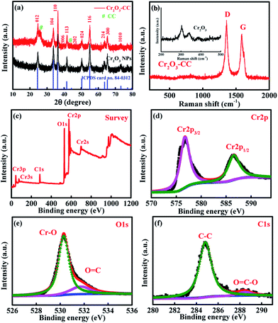
The preparation procedure of Cr2O3-CC is schematically illustrated in Fig. 1, which involved two steps. First, CrOOH nanosheets were in situ grown on CC by a facile hydrothermal method (Fig. S1a†). Then, the Cr2O3-CC composite was obtained by annealing at 500 °C for 3 h in air. The XRD patterns given in Fig. 2a indicate that all diffraction peaks of Cr2O3-CC and Cr2O3 NPs can be assigned to the rhombohedral crystal structure (JCPDS card no. 84-0312). The peaks at 26.2° and 43.5° can be indexed to carbon arising from CC (Fig.S1b†). The Raman spectra shown in Fig. 2b exhibit two distinct peaks at ∼1340 and ∼1600 cm−1, which can be assigned to the D- and G-bands of CC, representing disordered phonon mode and graphitic structure, respectively. The bands below 400 cm−1 can be assigned to the external modes of Cr2O3 (shown in the inset of Fig. 2b), while the disappearance or weakening of the Raman fingerprint characteristic of Cr2O3-CC was caused by screening effects of CC. The XPS survey spectrum (Fig. 2c) discloses that Cr2O3-CC consisted of Cr, O and C elements. The high-resolution Cr 2p spectrum (Fig. 2d) shows two peaks at 586.5 and 576.7 eV which could be ascribed to Cr 2p1/2 and Cr 2p3/2, respectively.28 The high-resolution O 1s spectrum (Fig. 2e) has two peak at 530.3 and 531.8 eV corresponding to the O–Cr and O![[double bond, length as m-dash]](https://www.rsc.org/images/entities/char_e001.gif) C bonds, respectively, whereas the C 1s spectrum (Fig. 2f) displays two peaks at 284.8 and 288.5 eV that can be ascribed to the C–C and O
C bonds, respectively, whereas the C 1s spectrum (Fig. 2f) displays two peaks at 284.8 and 288.5 eV that can be ascribed to the C–C and O![[double bond, length as m-dash]](https://www.rsc.org/images/entities/char_e001.gif) C–O groups, respectively.
C–O groups, respectively.
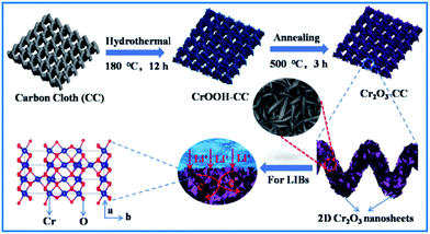 | ||
| Fig. 1 Schematic diagram of the preparation procedure of Cr2O3-CC with 2D Cr2O3 nanosheets grown on CC. | ||
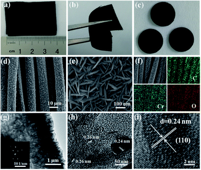
The digital photographs, FESEM and TEM images of Cr2O3-CC are given in Fig. 3 presenting its morphological and structural features. The Cr2O3-CC composite paper was flexible, mechanically robust and could be bent into arbitrary shapes (Fig. 3a and b). Moreover, it could be cut into disks of ∼1.13 cm2, which were used as freestanding anodes without adding binder or carbon additives (Fig. 3c). The Cr2O3-CC composite consisted of interconnected 2D Cr2O3 nanosheets grown on carbon fibers (Fig. 3d and e). The morphologies of Cr2O3-CC were essentially similar to the intermediate product, CrOOH-CC, obtained before annealing (Fig. S2 and S3a–c†), signifying that the structure of Cr2O3-CC remained unaltered even after annealing. The EDX measurement of Cr2O3-CC confirmed the co-existence of Cr, O and C elements (Fig. S4†), which were distributed uniformly along the whole carbon fiber surface, as confirmed by the elemental maps (Fig. 3f). An interesting architecture was uncovered by the HRTEM images (Fig. 3g and h) where the 2D Cr2O3 nanosheets were closely interconnected on the carbon fiber substrate. The Cr2O3-CC composite with a large surface area, once used as the anode, not only allowed fast charge transfer through the short diffusion pathways of Cr2O3 nanosheets, but also accommodated the volume expansion of Cr2O3 during the charge/discharge cycles by the CC substrate. The selected-area electron diffraction (SAED) pattern (in inset of Fig. 3g) revealed a polycrystalline nature of Cr2O3-CC. The marked lattice fringes with d-spacings of 0.24 and 0.26 nm correspond to the (104) and (110) planes of Cr2O3-CC (Fig. 3h and i).
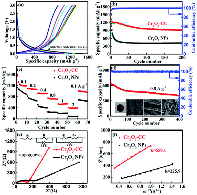
The electrochemical performance of the Cr2O3-CC and Cr2O3 NP anodes for LIBs is shown in Fig. 4. The discharge/charge voltage profiles (Fig. 4a) present the discharge and charge capacities of 1547.8 and 1310 mA h g−1, respectively, upon the first cycle of the Cr2O3-CC electrode along with an initial coulombic efficiency (CE) of 84.7%. The irreversible capacity loss in the first cycle can be attributed to the inevitable decomposition of electrolyte and the formation of solid electrolyte interface (SEI) on the electrode surface.40,41 Obviously, the Cr2O3-CC electrode exhibited much stabler cyclic stability than the Cr2O3 NP counterpart, with a high discharge capacity of 917.3 mA h g−1 retained after 200 cycles at 0.1 A g−1 for the former (Fig. 4b). In addition, an almost 100% CE was maintained in the second cycle and on wards of the Cr2O3-CC electrode, indicating its high reversibility. The cyclic performances of Cr2O3-CC with different mass loadings of Cr2O3 were also tested (Fig. S5†), indicating the Cr2O3-CC (7.94 wt%) shows the best performance. The relative cyclic performance of CC was poor with very low specific capacities (Fig. S6a†), confirming its almost negligible capacity contribution to the Cr2O3-CC electrode. The Cr2O3-CC electrode delivered high capacities of 1210, 1092, 914.4, 752.4, 540 and 414.2 mA h g−1 at 0.1, 0.2, 0.4, 0.8, 1 and 2 A g−1, respectively, which were 300–500 mA h g−1 higher than the corresponding values of the Cr2O3 NP counterpart, as shown in Fig. 4c. When the rate was reverted to 0.1 A g−1, the capacity of Cr2O3-CC recovered to 1005 mA h g−1, indicative of remarkable electrochemical reversibility and robustness of the electrode. Fig. 4d shows the long-term cyclic stability of the Cr2O3-CC electrode at 0.8 A g−1, which was tested without pre-activation. Remarkably, it exhibited outstanding cyclic performance with a high discharge capacity of 397 mA h g−1 after 400 cycles at 0.8 A g−1. It is worth noting that these values are better than or on par with the state-of-the-art results reported on similar Cr2O3 anodes (see details in Table 1). The inset Fig. 4d presents a digital and FESEM images taken of the Cr2O3-CC electrode after 400 cycles. It is clearly seen that the Cr2O3 nanosheets remained largely intact on the carbon fiber substrate without any signs of fracture or decomposition, signifying a robust and durable structure in the corrosive chemical environment of the electrolyte. The robust and flexible carbon fibers in CC functioned as buffer to accommodate volume changes while offering a large surface area for electrolyte. Fig. 4e shows the EIS spectra of the Cr2O3-CC and Cr2O3 NP electrodes. The high frequency intercept at the Z′ axis corresponds to the ohmic resistance (Rs), which represents the resistance of the electrolyte solution, and the semicircle in the mid-frequency range corresponds to the charge transfer resistance (Rct). The inclined line in the low frequency range represents the Warburg impedance (Zw), which is associated with Li+ diffusion. The EIS spectra were fitted with the circuit model given in inset of Fig. 4e and the impedance parameters thereby determined are summarized in Table S1.† The Rct value was much smaller for Cr2O3-CC than for Cr2O3 NPs, i.e. 140 vs. 217 Ω, indicating a faster charge transfer for the former electrode. Zw is a measure of lithium diffusion within the electrode and thus a higher slope with a lower Zw value of Cr2O3-CC meant better lithium diffusion than Cr2O3 NPs.42 The lithium ion diffusion coefficient, DLi+, is given by eqn (1):43–45
| DLi+ = [RT/√2(An2F2σC)]2 | (1) |
| Cr2O3-based electrodes | Synthesis method | Current density (mA g−1)/rate | Cycle number | Specific capacity (mA h g−1) | Ref. |
|---|---|---|---|---|---|
| Cr2O3 sheet | Solution combustion | 100 | 55 | 480 | 25 |
| M-C-Cr2O3 | Template method | 50 | 80 | 639 | 26 |
| Cr2O3-NPs@NC | Hydrothermal method | 100 | 203 | 568 | 27 |
| Cr2O3/C | Solution combustion | 100 | 55 | 710 | 28 |
| Cr2O3–C | Non-sacrificial template | 200 | 35 | 600 | 29 |
| Cr2O3-CNT(0.08%) | Chemical co-precipitation method | 100 | 200 | 995.3 | 30 |
| Cr2O3/carbon | Sol–gel approach | 100 | 150 | 465.5 | 31 |
| Cr2O3/C | Ballmilling | 100 | 20 | 650 | 46 |
| Cr2O3/FLG/Ni | Pulsed laser deposited | 100 | 50 | 543 | 47 |
| graphene/Cr2O3 | Hydrothermal method | 0.1C | 100 | 580 | 48 |
| Cr2O3/NC | Bio-template method | 100 | 100 | 640 | 49 |
| 1000 | 50 | 360 | |||
| Graphene-Cr2O3 | Hydrothermal method | 200 | 50 | 850 | 50 |
| C–Cr2O3 | Vacuum assisted impregnation | 0.1C | 100 | 540 | 51 |
| Cr2O3/C nanofiber | Electrospinning | 100 | 100 | 527 | 52 |
| Cr2O3@C@G | Spray drying | 100 | 120 | 648 | 53 |
| Cr2O3/C | Ballmilling | 100 | 50 | 530 | 54 |
| Cr2O3-GICs | Intercalation transformation | 100 | 1000 | 520 | 55 |
| Our work (Cr2O3-CC) | Hydrothermal method | 100 | 200 | 916.6 | |
| 800 | 400 | 414.2 |
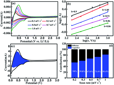
To explain the excellent rate performance of Cr2O3-CC, its kinetics was analyzed and the sources of capacity were probed, as shown in Fig. 5. The CV curves displayed essentially a similar shape and a broad peak profile for all scan rates between 0.2 to 1.0 mV s−1 (Fig. 5a) and for the first five cycles at 0.1 mV s−1 (Fig. S7†). In general, both the intercalation and capacitive reactions contribute to capacities of the electrodes at a high current density.45,56 The log(i) vs. log(v) plots of the Cr2O3-CC electrode are presented in Fig. 5b at different voltages, where the slope of the fitted line is denoted by b. When the b value approaches 1, the electrochemical system is controlled mainly by the pseudocapacitive effect, but when the b value is close to 0.5, the ionic diffusion process dominates. Here, the b values are seen higher than 0.8, signifying a high pseudocapacitive contribution.57 The individual contributions from both the pseudocapacitive (k1 v) and diffusion-controlled responses (k2 v1/2) were quantitatively analyzed based on the exponential relationship with scan rate:56–58
| i = k1 v1/2 + k2 v1/2 | (2) |
To explore the mechanisms behind the growth of Cr2O3 on carbon fibers, the DFT calculations were performed and the formation energy, Ef, of horizontally-stacked Cr2O3-CC was obtained according to eqn (3), where ECr2O3-CC, ECr2O3 and ECC are the total DFT energies of Cr2O3-CC, Cr2O3 and CC, respectively:
| Ef = ECr2O3-CC − ECr2O3 − ECC | (3) |
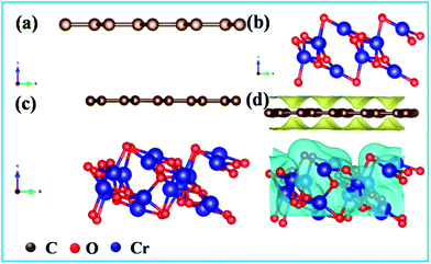
The optimized structures of CC, Cr2O3 and Cr2O3-CC are shown in Fig. 6a–c. A negative formation energy, Ef = −0.52 eV, was obtained for Cr2O3-CC, signifying thermodynamically favorable growth of Cr2O3 nanosheets on carbon fibers (Fig. 6d) during the annealing process.
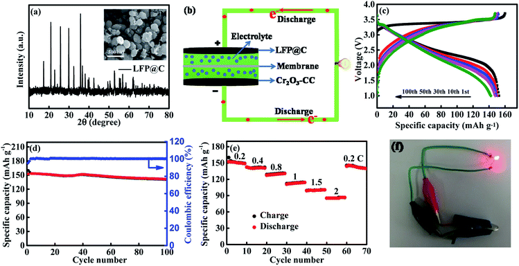
To demonstrate practical applications of Cr2O3-CC electrodes with superior half-cell electrochemical performance, full cells were assembled using the Cr2O3-CC anode and a commercial LiFePO4 (LFP) cathode, as schematically shown in Fig. 7b. Fig. 7a shows the XRD pattern of LFP@C with its FESEM image in inset, presenting spherical nanoparticles of ∼300 nm in diameter. Before the full cell was assembled, the Cr2O3-CC anode was pre-lithiated by direct contact with Li foil. In designing the full-cell battery, it is of paramount importance to optimize the loadings of cathode and anode to achieve the best electrochemical performance.61,62 Fig. 7c shows the voltage profiles of the full battery for voltages ranging 1–3.7 V at 1C for 1, 10, 30, 50 and 100 cycles. The initial discharge capacity was 152.4 m Ah g−1 calculated based on the cathode mass (1C = 170 mA g−1 vs. LFP), with an initial CE as high as 95.3%. The Cr2O3-CC//LFP@C full cell delivered excellent cyclic stability with a remaining discharge capacity of 140.6 mA h g−1 after 100 cycles (Fig. 7d), as well as superior rate performance (Fig. 7e). Specifically, the average capacities of the full cell were 150.6, 141, 129.1, 112.8, 99.9 and 85.7 mA h g−1 at 0.2, 0.4, 0.8, 1, 1.5, and 2 C, respectively. The long-term cyclic stability and the corresponding CE of the Cr2O3-CC//LFP@C full cell is shown in Fig. S10.† It is seen that the full cell exhibited 88.8% capacity retention for over 500 cycles at 1C. A CE of almost 100%, a crucial property for full cells, was maintained throughout the whole cycles after the initial value of 92.4%, verifying excellent reversibility of charge and discharge cycles. The real-world application of the full cell was also demonstrated to power a red light-emitting diode (LED with 2 V and 10 mW) bulb, as shown in Fig. 7f, which partly confirm the potential of Cr2O3-CC as the promising anode material for next-generation LIBs. Morever, when the flexible full cell was assembled using the commercial LiFePO4 powders as cathode as shown in Fig. S11,† a red light-emitting diode (LED) can be easily lighted at the bended state. The result confirms the potentiality of Cr2O3-CC as a anode material for flexible LIBs
Conclusions
In summary, we employed a simple hydrothermal method followed by thermal treatment to grow for the first time 2D Cr2O3 nanosheets on CC. The Cr2O3-CC composite was directly used as the freestanding anode without binder or conductive additives, which exhibited excellent lithium storage performance in terms of specific capacity, cyclic stability and rate capability. The interconnected Cr2O3 nanosheets on the CC substrate enabled fast charge transfer due to the short pathways of Cr2O3, while the conductive and flexible CC accommodated the volume expansion of Cr2O3 during the charge/discharge cycles. Moreover, the robust and durable structure with a large surface area gave rise to a high pseudocapacitance of Cr2O3-CC. Additionally, the full cell assembled with the Cr2O3-CC anode and a LiFePO4@C cathode manifested excellent capacity retention and rate capability. The design concept developed in this work is universal to all types of rechargeable batteries and can be readily extended to other electrode materials requiring superior capacities and rate performance.Conflicts of interest
There are no conflicts to declare.Acknowledgements
This work was supported by the National Natural Science Foundation of China (Grant number 21373107, 51904152, 51804156), and the Key Science and Technology Program of Henan Province (Grant number 192102210015).Notes and references
- M. S. Balogun, H. Yang, Y. Luo, W. T. Qiu, Y. C. Huang, Z. Q. Liu and Y. X. Tong, Energy Environ. Sci., 2018, 11, 1859–1869 RSC.
- C. Chen, Y. Zhang, Y. Li, Y. Kuang, J. Song, W. Luo, Y. Wang, Y. Yao, G. Pastel and J. Xie, Adv. Energy Mater., 2017, 7, 1700595 CrossRef.
- X. F. Wang, X. H. Lu, B. Liu, D. Chen, Y. X. Tong and G. Z. Shen, Adv. Mater., 2014, 26, 4763–4782 CrossRef CAS.
- G. M. Zhou, F. Li and H. M. Cheng, Energy Environ. Sci., 2014, 7, 1307–1338 RSC.
- Z. Gao, N. Song, Y. Zhang and X. Li, Nano Lett., 2015, 15, 8194–8203 CrossRef CAS.
- J. Cui, S. Yao, W. G. Chong, J. Wu, M. Ihsan-Ul-Haq, M. Zhao, Y. Wang and J. K. Kim, Chem. Mater., 2019, 31, 4113–4123 CrossRef CAS.
- R. J. Zou, Z. Y. Zhang, M. F. Yuen, M. L. Sun, J. Q. Hu, C. S. Lee and W. J. Zhang, NPG Asia Mater., 2015, 7, 195–212 CrossRef.
- Z. X. Liu, H. F. Li, M. S. Zhu, Y. Huang, Z. J. Tang, Z. X. Pei, Z. F. Wang, Z. C. Shi, J. Liu, Y. Huang and C. Y. Zhi, Nano Energy, 2018, 44, 164–173 CrossRef CAS.
- Z. N. Deng, H. Jiang, Y. J. Hu, Y. Liu, L. Zhang, H. L. Liu and C. Z. Li, Adv. Mater., 2017, 29, 1603020 CrossRef PubMed.
- D. L. Guo, J. W. Qin, Z. G. Yin, J. M. Bai, Y. K. Sun and M. H. Cao, Nano Energy, 2018, 45, 136–147 CrossRef CAS.
- J. Q. Tian, Q. Liu, A. M. Asiri and X. P. Sun, J. Am. Chem. Soc., 2014, 136, 7587–7590 CrossRef CAS.
- G. H. Zhang, S. C. Hou, H. Zhang, W. Zeng, F. L. Yan, C. C. Li and H. G. Duan, Adv. Energy Mater., 2015, 27, 2400–2405 CrossRef CAS.
- W. H. Li, M. W. Li, K. R. Adair, X. L. Sum and Y. Yu, J. Mater. Chem. A, 2017, 5, 13882–13906 RSC.
- X. Ao, H. Y. Sun, C. D. Wang, J. G. Li, Y. J. Ruan, B. Z. Li, Q. H. Wu, Y. Li, J. J. Jiang, Y. G. Yang and L. Q. Mai, Carbon, 2018, 130, 599–606 CrossRef CAS.
- Q. B. Zhang, H. X. Chen, L. L. Luo, B. T. Zhao, H. Luo, X. Han, J. W. Wang, C. M. Wang, Y. Yang, T. Zhu and M. L. Liu, Energy Environ. Sci., 2018, 11, 669–681 RSC.
- S. Liu, J. K. Feng, X. F. Bian, Y. T. Qian, J. Liu and H. Xu, Nano Energy, 2015, 13, 651–657 CrossRef CAS.
- Y. B. Zhao and A. Manthiram, Chem. Mater., 2015, 27, 3096–3101 CrossRef CAS.
- W. Xiao, J. Zhou, L. Yu, D. H. Wang and X. W. Lou, Angew. Chem., Int. Ed., 2016, 55, 7427–7431 CrossRef CAS.
- G. L. Liu, H. H. Wu, Q. Q. Meng, T. Zhang, D. Sun, X. Y. Jin, D. L. Guo, N. T. Wu, X. M. Liu and J. K. Kim, Nanoscale Horiz., 2019 10.1039/C9NH00402E.
- N. T. Wu, W. Z. Du, X. Gao, L. Zhao, G. L. Liu, X. M. Liu, H. Wu and Y. B. He, Nanoscale, 2018, 10, 11460–11466 RSC.
- L. Z. Zhao, H. H. Wu, C. H. Yang, Q. B. Zhang, G. M. Zhong, Z. M. Zheng, H. X. Chen, J. M. Wang, K. He, B. L. Wang, T. Zhu, X. C. Zeng, M. L. Liu and M. S. Wang, ACS Nano, 2018, 12, 12597–12611 CrossRef CAS PubMed.
- Y. Guo, Y. G. Zhang, Y. G. Wang, D. Y. Zhang, Y. Lu, R. J. Luo, Y. B. Wang, X. M. Liu, J. K. Kim and Y. S. Luo, Electrochim. Acta, 2019, 296, 989–998 CrossRef CAS.
- N. T. Wu, X. G. Qiao, J. K. Shen, G. L. Liu, T. Sun, H. Wu, H. S. Hou, X. M. Liu, Y. Zhang and X. B. Ji, Electrochim. Acta, 2019, 299, 540–548 CrossRef CAS.
- D. Zhao, J. W. Qin, L. R. Zheng and M. H. Cao, Chem. Mater., 2016, 28, 4180–4190 CrossRef CAS.
- Z. Q. Cao, M. L. Qin, B. R. Jia, L. Zhang, Q. Wan, M. S. Wang, A. A. Volinsky and X. H. Qu, Electrochim. Acta, 2014, 139, 76–81 CrossRef CAS.
- B. K. Guo, M. F. Chi, X. G. Sun and S. Dai, J. Power Sources, 2012, 205, 495–499 CrossRef CAS.
- Y. Zhao, J. J. Wang, C. L. Ma and Y. Li, Chem. Phys. Lett., 2018, 704, 31–36 CrossRef CAS.
- Z. Q. Cao and C. Y. Zuo, RSC Adv., 2017, 7, 40243–40248 RSC.
- L. Y. Jiang, S. Xin, X. L. Wu, H. Li, Y. G. Guo and L. J. Wan, J. Mater. Chem., 2010, 20, 7565–7569 RSC.
- S. M. Abbas, N. Ahmad, A. U. Rehman, U. A. Rana, S. U. D. Khan, S. Hussain and K. W. Nam, Electrochim. Acta, 2016, 212, 260–269 CrossRef CAS.
- Y. Fu, H. B. Gu, X. R. Yan, J. R. Liu, Y. R. Wang, J. N. Huang, X. Y. Li, H. L. Lv, X. Z. Wang, J. Guo, G. X. Lu, S. Qiu and Z. H. Guo, Chem. Eng. J., 2015, 277, 186–193 CrossRef CAS.
- S. H. Liu, Z. Y. Wang, C. Yu, H. B. Wu, G. Wang, Q. Dong, J. S. Qiu, A. Eychmuller and X. W. Lou, Adv. Mater., 2013, 25, 3462–3467 CrossRef CAS.
- Z. Y. Lin, G. Z. Liu, Y. P. Zheng, Y. B. Lin and Z. G. Huang, J. Mater. Chem. A, 2018, 6, 22655–22661 RSC.
- S. J. Hao, B. W. Zhang, Y. Wang, C. J. Li, J. Y. Feng, S. Ball, M. Srinivasan, J. S. Wu and Y. Z. Huang, Electrochim. Acta, 2018, 260, 965–973 CrossRef CAS.
- W. Q. Cao, W. Z. Wang, H. L. Shi, J. Wang, M. S. Cao, Y. J. Liang and M. Zhu, Nano Res., 2018, 11, 1437–1446 CrossRef CAS.
- J. P. Perdew, K. Burke and M. Ernzerhof, Phys. Rev. Lett., 1996, 77, 3865–3868 CrossRef CAS.
- P. E. Blöchl, Phys. Rev. B, 1994, 50, 17953–17979 CrossRef.
- P. E. Blöchl, O. Jepsen and O. K. Andersen, Phys. Rev. B, 1994, 49, 16223–16233 CrossRef.
- G. Stefan, J. Comput. Chem., 2006, 27, 1787–1799 CrossRef.
- N. T. Wu, J. K. Shen, L. Sun, M. Y. Yuan, Y. Y. Shao, J. M. Ma, G. L. Liu, D. L. Guo, X. M. Liu and Y. B. He, Electrochim. Acta, 2019, 310, 70–77 CrossRef CAS.
- Z. Q. Zhu, Y. X. Tang, Z. S. Lv, J. Q. Wei, Y. Y. Zhang, R. H. Wang, W. Zhang, H. R. Xia, M. Z. Ge and X. D. Chen, Angew. Chem., Int. Ed., 2018, 57, 3656–3660 CrossRef CAS.
- K. N. Zhao, F. N. Liu, C. J. Niu, W. W. Xu, Y. F. Dong, L. Zhang, S. M. Xie, M. Y. Yan, Q. L. Wei, D. Y. Zhao and L. Q. Mai, Adv. Sci., 2015, 2, 4443–4464 Search PubMed.
- M. Zhang, Y. W. Li, E. Uchaker, S. Candelaria, L. F. Shen, T. H. Wang and G. Z. Cao, Nano Energy, 2013, 2, 769–778 CrossRef CAS.
- J. Sun, H. W. Lee, M. Pasta, Y. M. Sun, W. Liu, Y. B. Li, H. R. Lee, N. Liu and Y. Cui, Energy Storage Materials, 2016, 4, 130–136 CrossRef.
- J. Cui, S. Yao, J. Q. Huang, L. Qin, W. G. Chong, Z. Sadighi, J. Huang, Z. Wang and J. K. Kim, Energy Storage Materials, 2017, 9, 85–95 CrossRef.
- J. Hu, H. Li and X. J. Huang, Electrochem. Solid-State Lett., 2005, 8, A66–A69 CrossRef CAS.
- Y. Zhao, J. J. Wang, C. L. Ma and Y. Li, Chem. Phys. Lett., 2018, 704, 31–36 CrossRef CAS.
- H. Xu, M. Zeng and J. Li, Int. J. Electrochem. Sci., 2015, 10, 7361–7370 CAS.
- S. Ma, Y. M. Xu, X. L. Cheng, X. F. Zhang, S. Gao, H. Zhao and L. H. Huo, Int. J. Electrochem. Sci., 2018, 13, 6048–6058 CrossRef CAS.
- G. Zhao, T. Wen, J. Zhang, J. Li, H. Dong, X. Wang, Y. Guo and W. Hu, J. Mater. Chem. A, 2014, 2, 944–948 RSC.
- H. Liu, X. W. Du, X. R. Xing, G. X. Wang and S. Z. Qiao, Chem. Commun., 2012, 48, 865–867 RSC.
- T. Yang, Z. Chen, H. Zhang, M. Zhang and T. Wang, Electrochim. Acta, 2016, 217, 55–61 CrossRef CAS.
- Y. Xiang, Z. Chen, C. M. Chen, T. H. Wang and M. Zhang, J. Alloys Compd., 2017, 724, 406–412 CrossRef CAS.
- X. Zhao, Q. C. Zhuang, S. D. Xu, Y. X. Xu, Y. L. Shi and X. X. Zhang, J. Electrochem. Soc., 2015, 162, A1156–A1162 CrossRef CAS.
- F. Wang, W. Li, M. Y. Hou, C. Li, Y. G. Wang and Y. Y. Xia, J. Mater. Chem. A, 2015, 3, 1703–1708 RSC.
- T. Brezesinski, J. Wang, S. H. Tolbert and B. Dunn, Nat. Mater., 2010, 9, 146–151 CrossRef CAS.
- C. Yang, Y. L. Zhang, F. Lv, C. F. Lin, Y. Liu, K. Wang, J. R. Feng, X. H. Wang, Y. J. Chen, J. B. Li and S. J. Guo, J. Mater. Chem. A, 2017, 5, 22297–22304 RSC.
- J. Cui, S. Yao, Z. H. Lu, J. Q. Huang, W. G. Chong, F. Ciucci and J. K. Kim, Adv. Energy Mater., 2018, 8, 1702488 CrossRef.
- S. Yao, J. Cui, Y. Deng, W. G. Chong, J. Wu, M. Ihsan-Ul-Haq, Y. W. Mai and J. K. Kim, Energy Storage Materials, 2019, 20, 36–45 CrossRef.
- C. T. Zhao, C. Yu, M. D. Zhang, H. W. Huang, S. F. Li, X. T. Han, Z. B. Liu, J. Yang, W. Xiao, J. N. Liang, X. L. Sun and J. S. Qiu, Adv. Energy Mater., 2017, 1602880 CrossRef.
- J. Hassoun, F. Bonaccorso, M. Agostini, M. Angelucci, M. G. Betti, R. Cingolani, M. Gemmi, C. Mariani, S. Panero, V. Pellegrini and B. Scrosati, Nano Lett., 2014, 14, 4901–4906 CrossRef CAS.
- Z. G. Yin, J. W. Qin, W. Wang and M. H. Cao, Nano Energy, 2017, 31, 367–376 CrossRef CAS.
Footnote |
| † Electronic supplementary information (ESI) available. See DOI: 10.1039/c9ra07465a |
| This journal is © The Royal Society of Chemistry 2019 |

