 Open Access Article
Creative Commons Attribution 3.0 Unported Licence
Development of customized 3D printed stainless steel reactors with inline oxygen sensors for aerobic oxidation of Grignard reagents in continuous flow†
Manuel C.
Maier
 ab,
René
Lebl
ac,
Philipp
Sulzer
ad,
Josef
Lechner
ab,
Torsten
Mayr
ab,
René
Lebl
ac,
Philipp
Sulzer
ad,
Josef
Lechner
ab,
Torsten
Mayr
 ad,
Matej
Zadravec
a,
Eyke
Slama
a,
Stefan
Pfanner
e,
Christoph
Schmölzer
f,
Peter
Pöchlauer
f,
C. Oliver
Kappe
 ac and
Heidrun
Gruber-Woelfler
 *ab
*ab
aCenter for Continuous Flow Synthesis and Processing (CC FLOW), Research Center Pharmaceutical Engineering GmbH (RCPE), Graz, Austria
bInstitute of Process and Particle Engineering, Graz University of Technology, Graz, Austria. E-mail: woelfler@tugraz.at
cInstitute of Chemistry, University of Graz, Graz, Austria
dInstitute of Analytical Chemistry and Food Chemistry, Graz University of Technology, Graz, Austria
eAnton Paar GmbH, Graz, Austria
fPatheon Austria GmbH & Co KG, part of Thermo Fisher Scientific, Linz, Austria
First published on 12th December 2018
Abstract
Additive manufacturing has gained a lot of interest in recent years to create customized reactors and equipment for milli- and micro flow applications. This work presents the development of 3D printed stainless steel reactors for the oxidation of Grignard reagents in flow. In our first approach a 3D printed micro CSTR-cascade was designed as a tool to get more insight in the reaction kinetics. Novel optical sensors were integrated inline in the cascade to monitor the oxygen consumption in real time. Based on the obtained experimental data and CFD simulations, a customized 3D printed split and recombine reactor was designed especially for the needs of the reaction.
Introduction
Organic flow chemistry has developed an increasing interest in performing syntheses in milli- and microreactors.1–3 These reactors offer the potential for intensified process conditions through high mass and heat transfer rates due to high surface-to-volume ratios.4,5 Milli- and microreactors enable novel reactions to be developed at conditions not easily realized in conventional batch processing. While there are straightforward and cheap ways to set up micro flow processes with standardised tubings as reactors, their mixing properties lack the possibility to be optimized to the predefined process conditions. This missing optimization often results in low product yields with unwanted side product formation.6,7 Therefore, a trend has emerged to manufacture chip-like microreactors for these predefined mixing operations. These 2D chip-like reactors are often made of glass or poly-dimethylsiloxane (PDMS), fabricated by etching and micromolding through expensive manual labour. Subsequent adaption or expansion of these reactors is difficult to achieve due to the lack of robust chip-to-chip interconnections.8Rapid developments in the field of 3D printing show a successful production of milli- and microreactors especially designed for the needs of the process.9–17 The lack of robust interconnections can be eliminated through compact design of system parts and thus compacter production lines can be achieved.18 However, most of these 3D printed reactors are made of plastics which are unsuitable for most organic solvents. Another drawback of the frequently used polymers is the poor heat transfer characteristics, leading to the formation of possible hot spots during the reaction. Selective laser melting (SLM) of stainless steel is a suitable 3D printing technique to overcome these limitations.19–26 SLM printed microreactors show high thermal conductivity, mechanical strength and thermal resistance over a broad range of temperatures. Stainless steel can be easily post processed after the printing in the mechanical workshop, enabling the connection to standard HPLC equipment.
This work reports the development of customized SLM printed stainless steel reactors for the continuous aerobic oxidation of Grignard reagents. To investigate the intrinsic reaction kinetics, the problem of the coupled mass transfer and proceeding reaction was eliminated by absorbing oxygen beforehand in the solvent. This absorption reduces the reaction to a one phase mixing dependant case. The reactor design for the resulting one phase system was guided by monitoring the oxygen consumption rate during oxidation of the Grignard reagent through implemented novel optical inline oxygen sensors. These sensors show high resistance against the used organic solvent, are able to measure high oxygen concentrations, and respond quickly to changes in the system, thus making them especially useful for fast reactions.
For the reactor design approach, a 3D printed micro CSTR cascade (AP01) was designed as a tool to measure the reaction rate. With this cascade it was possible to estimate the dependency of the oxidation reaction on the degree of mixing by monitoring the oxygen consumption rate with the integrated novel oxygen sensors in the CSTR vessels. An estimation of the intrinsic reaction time scale was possible and was used in combination with computational simulations and preliminary knowledge in advanced manufacturing technologies to manufacture another 3D printed reactor (AP02). This reactor is designed and adapted exactly to the requirements of the one phase Grignard reagent oxidation and utilizes novel 3D printed three-dimensional structures.
Model reaction – aerobic oxidation of Grignard reagents
Aerobic oxidation of Grignard reagents to the corresponding phenols was selected as a model reaction for the evaluation of both, oxygen sensor performance and mixing efficiency of the 3D printed reactors. This reaction was developed to provide an efficient green approach towards functionalized phenols using oxygen as an inexpensive and sustainable oxidant.27 It serves as an alternative for conventional reactions, such as nucleophilic aromatic substitution,28 oxidations using boronic acids,29 or cost intensive, toxic, transition-metal catalysis based hydroxylation.30Due to the reactive nature of Grignard reagents, their direct oxidation by oxygen is highly demanding in terms of heat and mass transfer. Based on the proposed mechanism of this reaction (Fig. 1), fast and efficient mixing is crucial to prevent stoichiometric imbalances, which may cause the formation of side products. Such limitations can be overcome by performing the reaction in a continuous flow regime, as both control over temperature and mixing performance can be enhanced.31 Furthermore, establishing a continuous flow process allows for an easier and safer execution of the reaction on larger scale, compared to conventional batch methods.32,33
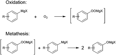 | ||
| Fig. 1 Proposed mechanism for the oxidation of Grignard reagents by oxygen via a peroxide intermediate. The initial step is expected to proceed via an electron transfer step between the Grignard reagent and oxygen.34 | ||
Therefore, this aerobic oxidation of Grignard reagents provides an interesting model reaction for further investigations towards reactor design from many points of view, especially considering its biphasic nature. Successful execution of this oxidation in a customised 3D printed reactor requires broad chemical resistance, good thermal conductivity, concise mixing and optional implementation of suitable process analytical technology (PAT).
Since oxygen is used as a reagent in stoichiometric amounts, accurate control over its dosing and effective concentration is highly desired for any kind of optimization or up-scaling. Exact dosing of gases can be easily accomplished in a continuous flow setup using calibrated mass flow controllers (MFC).
Inline measurement of the oxygen concentration by novel optical sensors within the flow reactor is a powerful tool to monitor the progress of reaction in real-time. In this work, the simultaneous use of multiple sensors at different stages of the reaction are used to provide further mechanistic insights.
Results and discussion
Reactor design
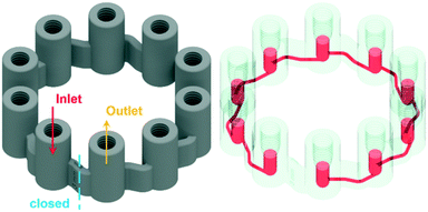
To operate a multiphase reactor at its optimum, it is important to characterize the rate limiting time scale. If the mass transfer time scale is significantly slower compared to the intrinsic reaction time scale, undesired by-product formation can occur. To investigate the intrinsic reaction time scale, the oxidation of the Grignard reagents is reduced to a homogeneous reaction system by absorbing oxygen in the solvent beforehand. This reduces the problem to a mixing rate limiting case of a homogeneous reaction system, which is well understood even for fast reactions.35 In passive mixing elements the degree of mixing of homogeneous reaction systems are predefined by the structures themselves and the operation conditions, i.e. inlet flow rates. To investigate a desired reaction with defined operation conditions, active mixing principles need to be applied. With active mixing, the degree of mixing can be controlled by parameters applied externally to the reactor. However, active mixing elements have the disadvantage that their correct operation has to be monitored. Once the desired process is known, it is economically advantageous to use static mixing elements designed for the prevailing conditions.The designed micro CSTR cascade (Fig. 2) has all of the above needed features to characterize a homogeneous reaction. It consists of 10 vessels with an internal diameter of 3 mm, stirred by a magnetic stirring spheroid of 2.4 mm wide and 2.7 mm long, powered and controlled by the magnetic field of a laboratory magnetic stirrer. Each vessel can be configured for different purposes by installing standard HPLC fittings/plugs to open or block its upper part. The vessels are connected to each other through 800 μm channels attached tangentially to the spherical bottom part of the vessel. The ring shaped cascade is blocked at a marked position, indicating the in-/outlet of the vessels. With the stirrers inside and fittings connected, the total reactor volume is 275.6 μL. By installing the developed novel optical fibre sensors with standard HPLC fittings, the oxygen consumption during the reaction can be monitored in the vessels. The effect of stirring on the rate of oxygen consumption can be influenced through adjusting the stirrer speed. When an increasing RPM does not lead to an increasing reaction rate, the operation point for the intrinsic reaction rate can be found.
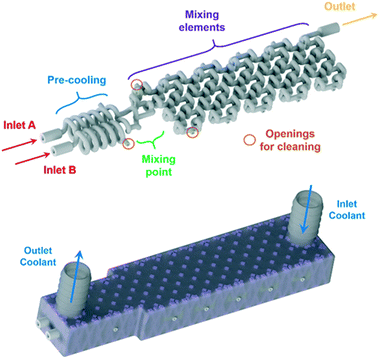
For the homogeneous reaction case of the Grignard reagent oxidation, a customized reactor (AP02, Fig. 3) was designed based on the experimentally obtained data from the CSTR cascade (AP01) and CFD simulations of an adapted split and recombine mixing structure (as shown below). The new reactor features fully scalable sections through a parameter depending CAD design, which enables numbering up approaches to reach higher throughputs. This scalability is possible since the basic setup of a flow reactor consists always of a precooling, mixing and reaction sections. The parameter dependency allows an arbitrarily scaling of each section by varying only three parameters while noticing the placing of each CAD drawing's origin at the point of mixing. This allows the fast interchange of section elements in the design phase of the reactor. The used parameters for the scaling of the sections are d, Le and n, the internal diameter, cubical element length scale and number of elements, respectively. This design allows to calculate the size of each reactor section by multiplying the element length with the number of elements. Through simple spreadsheet calculations it is possible to vary these parameters and directly update the design regarding the needs of the reaction. For the new split and recombine reactor, an internal diameter of 800 μm and an element length scale of 3.5 mm was chosen leading to a reactor volume of 0.565 ml for the mixing elements.
After the basic design of the reactor, the reaction channel was placed inside a cooling shell and openings were added at critical positions to ensure adequate cleaning of the delicate mixing structure. These openings were set to be easily accessible for welding from the outside of the cooling shell. For the layerwise printing, a support was needed to connect the reaction channel with its cooling shell. The support on the inside of the cooling shell was generated by Materialise's Magics software and adapted with a Boolean operation to fit the reaction channel. This operation subtracted the CAD drawing of the filled reaction channel body from the generated support, allowing to insert the hollow reaction channel into the final CAD file as the last step before printing.
Simulation
Computational fluid dynamics (CFD) simulation was used to evaluate the mixing geometry of the split and recombine reactor. The set of governing equations (i.e. Navier–Stokes equations) was solved using the Ansys-CFX software package. The geometry of the reactor has been discretized with a hexahedral cell dominated mesh (Fig. 4), which consisted of approx. 12 million cells and nodes. | ||
| Fig. 4 Details of numerical mesh at the beginning of the calculated domain of inlet A (left figure) and at the region of mixing elements (right figure). | ||
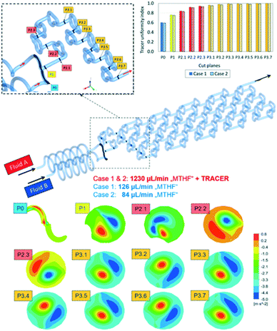
The CFD simulation was performed at steady-state. Boundary conditions were set to match the anticipated experimental conditions (shown later). Thus, a flow rate of 1230 μL min−1 was chosen for inlet A and two different flowrates, 126 μL min−1 (case 1) and 84 μL min−1 (case 2), were chosen for inlet B (Fig. 5). For quick mixing, it is desirable to bring the flow tendency to a “helical” flow pattern. This pattern can be represented by the velocity helicity, a parameter indicating counter current helical flow behaviour in different sections of the reactor.36 Helicity is a scalar quantity defined as an inner (dot) product of velocity and vorticity vectors. Fig. 5 shows the contour plots for the flow velocity helicity (bottom) at different cross-sections in the reactor. Two main counter current helical flow patterns can be observed on each cut plane, which change the circumferential position along the reactor. This changing position causes good mixing perpendicular to the main stream direction along the reaction channel.
Another measure of mixing performance is the uniformity index.37 It was calculated by applying a tracer at inlet A as a passive scalar through tracking the concentration at each cut plane along the reactor length. From the graph in Fig. 5 (top right) it can be seen that the tracer uniformity index across different cut planes is increased and reaches a maximum value in the middle of the cut plane section 3, indicating the tracer is fully premixed. With the tracer uniformity index, it was possible to conclude that there are no major differences between the two simulation cases. The obtained simulation results have shown that the designed mixer geometry will lead to very efficient mixing already at a very early stage in the mixing elements section.
3D printing
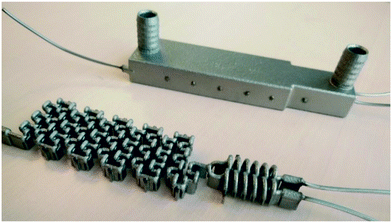
3D printing of the reactors was done by selective laser melting (SLM) to manufacture the stainless steel reactors shown in Fig. 6 and 7. As presented in a previous work,26 SLM printed reactors are well applicable for organic flow synthesis. Similar to other 3D printing techniques, the CAD drawing needs to be sliced first to generate cross-sectional layers (ESI,† Fig. S1), which were printed layer by layer through fusion of a metal powder bed. This sintering of the layers was done by an SLM system from EOS utilizing an ytterbium fibre laser with 400 Watt maximum power input, scanning through a 316 L stainless steel powder bed with a d50 of 35.9 μm. For the selected layer height of 40 μm, the laser melted the current layer and the prevailing one to generate well-bonded, gas-tight, high density builds.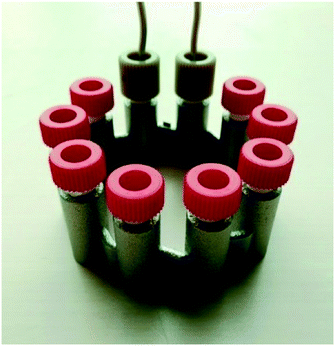 | ||
| Fig. 6 3D printed CSTR cascade (AP01) closed with standard HPLC fittings. The 3D printed 10–32 UNF thread had to be refined after the printing. | ||
After the printing process, the building platform was disassembled from the printer and the unused metal powder was collected for re-use. Inner parts of the prints were freed from the powder with compressed air, ultrasound treatment and dried again with compressed air. Afterwards, stress relief annealing of the printed parts was carried out in a vacuum oven. Next, the reactors were cut from the building platform by means of a band saw, and their surface was refined by sandblasting. Cleaning openings were closed by laser welding and the connection to standard equipment was enabled with 1/16′′ stainless steel capillaries welded to the in- and outlets. Finally, the prints were blasted with micro glass beads, and once again, brought into the ultrasonic bath followed by drying with compressed air. Due to the design of the CSTR cascade, welding to close the cleaning ports was not necessary, however, the 10–32 UNF printed threads were refined with a thread cutter.
Characterization of the 3D printed reactors
Due to the low Reynolds number in milli- and microreactors, laminar flow is predominant. As a result, mixing in these reactors must rely solely on diffusive mixing between the fluid elements, leading to long channels to achieve sufficient mixing.38 However, enhanced laminar mixing can be achieved through chaotic flows.39 This means large intermaterial contact areas are generated by stretching and folding of the fluid elements. The generation of chaotic flows in microreactors can be achieved through two mixing principles: passive and active.40 Passive mixing elements are an integral part of the fluid channel and are incorporated during the fabrication. Their efficiency depends on the prevailing process conditions. By applying active mixing elements, the degree of mixing can be controlled by user demands, however, the proper working of the mixing element needs to be monitored.In this work, the degree of mixing was characterized experimentally by monitoring the product distribution of the diazo coupling between 1-naphthol and diazotized sulphanilic acid,41 a system of competitive and consecutive reactions (ESI,† Fig. S2). Two isomeric monoazo dyes are formed via primary coupling – o-R and p-R. In a secondary coupling, both monoazo dyes react again with diazotized sulphanilic acid to form the bisazo dye (S). Because primary coupling is much faster compared to the secondary coupling, the yield of bisazo product S (eqn (1)) is related to the mixing performance, i.e. the less product S is formed, the better the mixing. An initial solution of diazonium salt was prepared by diazotization of 10 mmol L−1 sulphanilic acid with sodium nitrite and hydrochloric acid. This solution was diluted to 1 mmol L−1 for the experiments. The second solution contained 1.2 mmol L−1 1-naphthol dissolved in a buffer solution with 222.2 mmol L−1 of sodium carbonate and sodium bicarbonate, respectively. Both solutions combined lead to a pH of 9.9 and ionic strength of 444.4 mmol L−1 for the coupling reaction. The experiments were carried out at 25 °C and equal volumetric flow rates. Samples were collected after flushing the reactor for three residence times to reach steady state. Concentration of each component was determined by light absorption measurement for several wavelengths and multi-parameter-linear-regression of the absorption spectra. This regression used molar extinction coefficients for each substance based on literature42 (ESI,† Table S1). Due to the overlapping spectra of the monoazo dyes only their sum can be determined correctly. To check for experimental errors, the mass balance of each sample was calculated based on reagent B, which was in depletion. Using this procedure, the experimental error was found to be higher at lower flow rates.
 | (1) |
The obtained mixing behaviour of the printed reactors in Fig. 8 indicates far better performance of both reactors compared to a simple T-mixer. The especially high mixing rates achieved at low flow rates with stirring in the CSTR cascade indicate its applicability for measurements of relatively fast reactions. At high flow rates, a changing RPM has shown no effect on the mixing performance of the reactor (ESI,† Fig. S3 and S4). The set RPMs are not controlled within the cascade and only refer to set values of the laboratory magnetic stirrer. Inertial forces at higher flow rate might influence the small stirring spheroids RPM until their rotation is only induced by the flowing fluid.
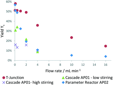 | ||
| Fig. 8 Mixing performance evaluated at process conditions in the 3D printed reactors (AP02 = split and recombine reactor, AP01 = cascade) and compared to a standard HPLC T-junction. | ||
In addition to the mixing evaluation, the residence time distribution (RTD) of both printed reactors was investigated. RTD experiments were performed with fibre optic probes for the detection of a tracer solution within an inline UV/VIS flow cell. An instantaneous step change from solvent (12 w% ethanol in water) to tracer solution (0.006 v% anisole in previously mentioned solvent mixture) was possible by using a manual 6-way valve. The RTD was evaluated for equal Reynolds numbers as at process conditions for both printed reactors (ESI,† Fig. S5 and S6). The split and recombine reactor AP02 showed plug flow like behaviour at approximately 1.8 ml min−1 indicated by a calculated Bodenstein number close to 100. For the cascade AP01, a Bodenstein number close to 20 was obtained at process conditions, indicating a CSTR like behaviour. Large deviations from plug flow can be assumed at Bodenstein numbers below 100 leading to higher axial dispersion.43
Implementation of novel optical oxygen sensors in the set-up
To follow the chemical transformation, inline oxygen monitoring was implemented into the reactors. The novel oxygen sensors are based on a phase fluorimetry readout system.44 They are applicable for pressurized systems in the presence of organic solvents and high oxygen concentrations by utilizing tailored fibre based optical sensors. Compared to commonly employed sensor materials like sol–gels and polymers with high oxygen diffusivity,44 the developed sensors use more robust materials. A NIR-emitting Pt-tetra(4-fluorophenyl)tetrabenzoporphyrin (PtTPTBPF)45 dye was immobilized in polyphenylenesulfide (PPS) and coated with a CYTOP® protection coating. By affixing the sensor fibre into a standard HPLC fitting, it was ready to be implemented into the reactors (Fig. S7 and S8, ESI†).The sensor data is read out with a commercial miniaturized USB phase fluorimeter (FireStingO2) using a custom made Python based evaluation software. The calibration of the sensor can be performed within the reaction environment by controlling the oxygen concentration via syringe pumps and mass flow controller. Thorough investigations revealed that the sensor operates according to a linear Stern–Volmer equation,46 which allows a two-point calibration of oxygen concentration (Fig. 9). This two-point calibration allows fast initializing of the sensors at process conditions within the reactor itself.
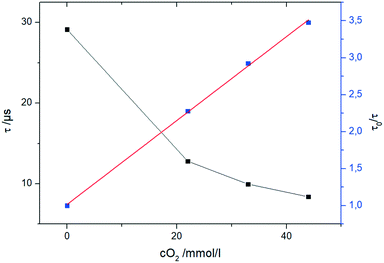 | ||
| Fig. 9 Evaluation of the oxygen calibration with the fibre sensor in THF at 0 °C and oxygen concentrations up to 42 mmol L−1. | ||
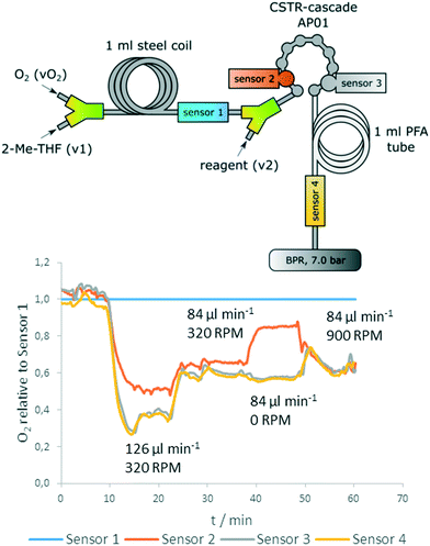
Fig. 10 (top) shows positions of the sensors in the reactor setup. Two sensors were introduced before and after the reactor for reference measurements, whereas two sensors were directly implemented into the CSTR cascade (first and last chamber). Sensor 1 is used as a reference for determination of the actual oxygen concentration that is inserted before addition of the reagent. The reference is also used to correct the data of pump related fluctuations (Fig. S9, ESI†).
The data show clearly: the concentration of starting material (4-methoxyphenylmagnesium bromide) correlates with oxygen consumption and the reaction rate depends on stirrer speed (Fig. 10, bottom). Whereas 0 RPM leads to a significantly decreased conversion in compartment 1 of the cascade, the last section of the measurement (minute 50–60) shows that at 900 RPM the reaction is already completely finished at sensor 2 (no further oxygen decrease between sensor 2 and 3). Additionally, the data obtained from the inline measurements with the oxygen sensors indicated a rapid intrinsic chemical reaction, as no further oxygen consumption was observed after an additional residence time coil.
Oxidation of Grignard reagents in the novel reactors
The aerobic oxidation of Grignard reagents was chosen as a model reaction to evaluate the 3D printed reactors. This evaluation was supported by inline measurements of oxygen concentrations with the novel optical sensors. The reaction outcome was compared for the aerobic oxidation of 4-chlorophenylmagnesium bromide 1 (Scheme 1) utilizing the two 3D printed reactors (AP01 and AP02) and a standard flow reactor made of PFA tubing (0.8 mm ID).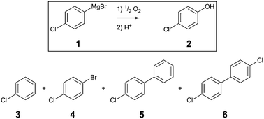 | ||
| Scheme 1 Aerobic oxidation of 4-chlorophenylmagnesium bromide 1 including the desired product 2, quenched starting material 3 and the side products 4, 5 and 6. | ||
Fig. 11 shows a flow chart for the reaction with the first feed to the reactor containing 1 equiv. of oxygen pre-dissolved in 2-methyltetrahydrofuran (2-Me-THF) and the second feed consisting of a 1 M solution of substrate 1 in 2-Me-THF. For the reactions using PFA coil and CSTR cascade, those two feeds were combined by a Y-mixer (ESI,† Fig. S8). To ensure the inline measurement of a stable oxygen concentration by the optical sensors, absorption of oxygen (added by a mass-flow controller) in 2-Me-THF (degassed by purging it with argon prior to the reaction) was done using a stainless steel coil. Before mixing the oxygen solution with the pre-cooled reagent, a reference oxygen sensor was added to all three setups (Sa in Fig. 11). All sensors were calibrated prior to the experiments, and are capable of measuring actual oxygen concentrations within the organic solvent. Oxygen concentration for reactions conducted in the split and recombine reactor AP02 could only be measured at its outlet, whereby the CSTR cascade AP01 allowed for direct implementation of sensors at different intermediate positions. A final oxygen sensor (Sb in Fig. 11) was included as a second reference directly before the back pressure regulator (BPR) in all setups. A BPR was used to ensure a constant pressure of 7 bar in the system.
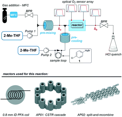 | ||
| Fig. 11 General scheme of the reaction set-up to carry out the aerobic oxidation of 1 in three different reactors including the positioning of the optical oxygen sensors. | ||
The reactions were carried out at 0 °C with flow rates of 1000 μl min−1 2-Me-THF, 1500 μl min−1 oxygen (at norm conditions) and 126 μl min−1 of the Grignard reagent 1 using a stoichiometric ratio of 1![[thin space (1/6-em)]](https://www.rsc.org/images/entities/char_2009.gif) :
:![[thin space (1/6-em)]](https://www.rsc.org/images/entities/char_2009.gif) 1 between oxygen and reagent. Complete absorption of oxygen in the solvent at 7 bar was checked prior to mixing with the reagent with transparent tubes. The exiting stream was immediately quenched at the reactor outlet by 0.5 M aqueous HCl. Notably, small gas segments were observed at the outlet after the BPR, pointing to the presence of unconsumed O2 in the resulting solution. Crude reaction mixtures were then analysed by GC-MS and GC-FID chromatography. The samples were prepared by extraction of the quenched reaction mixture with CH2Cl2.
1 between oxygen and reagent. Complete absorption of oxygen in the solvent at 7 bar was checked prior to mixing with the reagent with transparent tubes. The exiting stream was immediately quenched at the reactor outlet by 0.5 M aqueous HCl. Notably, small gas segments were observed at the outlet after the BPR, pointing to the presence of unconsumed O2 in the resulting solution. Crude reaction mixtures were then analysed by GC-MS and GC-FID chromatography. The samples were prepared by extraction of the quenched reaction mixture with CH2Cl2.
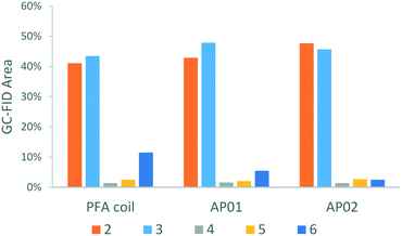
Along with the desired product, 4-chlorophenol 2, four different species could be identified by GC-MS analysis (Scheme 1): chlorobenzene 3, which resulted from the reaction quench and three side products 4, 5, and 6 which were presumably formed from radical intermediates. Especially the dichloro-biphenyl product 6 implies the recombination of two chlorophenyl radicals, which might have resulted from stoichiometric imbalances (high local concentrations) due to lower mixing performance. The identities of the two major products 2 and 3 were additionally confirmed by reference substances using GC-FID.
As illustrated by the product distribution in Fig. 12, considerable reduction of the major side-product 6 could be observed in the printed reactors. This side-product content started at 11.5% in the PFA coil experiment and was reduced to 5.5% in the CSTR cascade AP01, and to 2.5% in the split and recombine reactor AP02. Increased selectivity can be ascribed mainly to a better mixing efficiency which limits the rapid chemical transformation as shown in the CSTR experiment (Fig. 10, bottom). The higher selectivity in reactor AP02 can be explained by a more efficient design of the mixing point in contrast to the used Y-junction as first contact point in the other set ups. Therefore, the cascade AP01 performed worse as might be predicted by the mixing sensitive experiments in Fig. 8, where the reaction was started directly in the cascade's second vessel. Additionally, selectivity might also be influenced by the employed reactor material as a better heat management in the reactors was possible through higher thermal conductivity of stainless steel compared to regular PFA.
Conclusions
In this work, a combination of SLM 3D printing of stainless steel and the implementation of novel oxygen sensors for the inline measurement was shown to be a promising combination for investigating the oxidation of Grignard reagents in flow. 3D printing is a favourable tool for the creation of adaptable reactors and implementation of sensors. With the parameter dependency, the CAD files used for the printing can be quickly adapted to the desired process conditions and directly used for CFD simulations to predict the flow behaviour and mixing quality. This developed reactor design concept can be used later on for up-scaling approaches to reach higher throughputs. To monitor the processes inside the reactor, sensor ports can be easily implemented into the 3D designs utilizing standard HPLC equipment for the connection. The sensors developed within this work are applicable for high oxygen concentration measurements in pressurised flow systems in the presence of organic solvents. They can be initialized by two-point calibration within the reactor in a short amount of time. By combining the possibilities of 3D printing with the novel sensors, it was possible to 3D print a micro CSTR cascade as a tool for the reaction investigation incorporating these novel sensors. A fast progress of the reaction was confirmed in the cascade by varying the degree of mixing while monitoring the oxygen consumption with the novel sensors. The obtained insights on the reaction time scale served as basis for the design of a static mixing split and recombine reactor, which was adapted to the predefined operation conditions. The experimental characterization of both 3D printed reactors was done by mixing dependant reactions, RTD analysis and the aerobic oxidation of 4-chlorophenylmagnesium bromide. Both printed reactors showed high mixing rates and increased selectivity compared to the reaction in a conventional reaction setup consisting of a PFA coil and a Y-junction as mixer.Future work will focus on the influence of surface roughness on the mixing efficiency as well as on a more detailed investigation of the influence of reactor geometry on the reaction outcome.
Conflicts of interest
There are no conflicts to declare.Acknowledgements
The CC FLOW project (Austrian Research Promotion Agency FFG No. 862766) is funded through the Austrian COMET Program by the Austrian Federal Ministry of Transport, Innovation and Technology (BMVIT), the Austrian Federal Ministry of Science, Research and Economy (BMWFW) and by the State of Styria (Styrian Funding Agency SFG).Notes and references
- M. B. Plutschack, B. Pieber, K. Gilmore and P. H. Seeberger, Chem. Rev., 2017, 117, 11796–11893 CrossRef CAS PubMed.
- M. Movsisyan, E. I. P. Delbeke, J. K. E. T. Berton, C. Battilocchio, S. V. Ley and C. V. Stevens, Chem. Soc. Rev., 2016, 45, 4892–4928 RSC.
- B. Gutmann, D. Cantillo and C. O. Kappe, Angew. Chem., Int. Ed., 2015, 54, 6688–6728 CrossRef CAS PubMed.
- V. Hessel, D. Kralisch and N. Kockmann, Novel Process Windows, Wiley-VCH Verlag GmbH & Co. KGaA, Weinheim, Germany, 2014 Search PubMed.
- N. Kockmann, P. Thenée, C. Fleischer-Trebes, G. Laudadio and T. Noël, React. Chem. Eng., 2017, 2, 258–280 RSC.
- S. Schwolow, J. Hollmann, B. Schenkel and T. Röder, Org. Process Res. Dev., 2012, 16, 1513–1522 CrossRef CAS.
- J. M. Reckamp, A. Bindels, S. Duffield, Y. C. Liu, E. Bradford, E. Ricci, F. Susanne and A. Rutter, Org. Process Res. Dev., 2017, 21, 816–820 CrossRef CAS.
- A. Günther and K. F. Jensen, Lab Chip, 2006, 6, 1487–1503 RSC.
- N. Bhattacharjee, A. Urrios, S. Kang and A. Folch, Lab Chip, 2016, 16, 1720–1742 RSC.
- A. K. Au, W. Huynh, L. F. Horowitz and A. Folch, Angew. Chem., Int. Ed., 2016, 55, 3862–3881 CrossRef CAS PubMed.
- R. Amin, S. Knowlton, A. Hart, B. Yenilmez, F. Ghaderinezhad, S. Katebifar, M. Messina, A. Khademhosseini and S. Tasoglu, Biofabrication, 2016, 8, 022001 CrossRef PubMed.
- B. C. Gross, J. L. Erkal, S. Y. Lockwood, C. Chen and D. M. Spence, Anal. Chem., 2014, 86, 3240–3253 CrossRef CAS PubMed.
- Y. He, Y. Wu, J. Fu, Q. Gao and J. Qiu, Electroanalysis, 2016, 28, 1658–1678 CrossRef CAS.
- B. Gross, S. Y. Lockwood and D. M. Spence, Anal. Chem., 2017, 89, 57–70 CrossRef CAS PubMed.
- C. Parra-Cabrera, C. Achille, S. Kuhn and R. Ameloot, Chem. Soc. Rev., 2018, 47, 209–230 RSC.
- P. J. Kitson, S. Glatzel, W. Chen, C.-G. Lin, Y.-F. Song and L. Cronin, Nat. Protoc., 2016, 11, 920–936 CrossRef CAS PubMed.
- A. J. Capel, R. P. Rimington, M. P. Lewis and S. D. R. Christie, Nat. Rev. Chem., 2018, 2397–3358 Search PubMed.
- P. J. Kitson, G. Marie, J.-P. Francoia, S. S. Zalesskiy, R. C. Sigerson, J. S. Mathieson and L. Cronin, Science, 2018, 359, 314–319 CrossRef CAS PubMed.
- A. J. Capel, S. Edmondson, S. D. R. R. Christie, R. D. Goodridge, R. J. Bibb and M. Thurstans, Lab Chip, 2013, 13, 4583–4590 RSC.
- A. J. Capel, A. Wright, M. J. Harding, G. W. Weaver, Y. Li, R. A. Harris, S. Edmondson, R. D. Goodridge and S. D. R. Christie, Beilstein J. Org. Chem., 2017, 13, 111–119 CrossRef CAS PubMed.
- R. Reintjens, D. J. Ager and A. H. M. De Vries, Chim. Oggi, 2015, 33, 21–24 Search PubMed.
- G. Scotti, V. Matilainen, P. Kanninen, H. Piili, A. Salminen, T. Kallio and S. Franssila, J. Power Sources, 2014, 272, 356–361 CrossRef CAS.
- G. Scotti, P. Kanninen, V.-P. Matilainen, A. Salminen and T. Kallio, Energy, 2016, 106, 475–481 CrossRef CAS.
- S. Sandron, B. Heery, V. Gupta, D. A. Collins, E. P. Nesterenko, P. N. Nesterenko, M. Talebi, S. Beirne, F. Thompson, G. G. Wallace, D. Brabazon, F. Regan and B. Paull, Analyst, 2014, 139, 6343–6347 RSC.
- V. Gupta, M. Talebi, J. Deverell, S. Sandron, P. N. Nesterenko, B. Heery, F. Thompson, S. Beirne, G. G. Wallace and B. Paull, Anal. Chim. Acta, 2016, 910, 84–94 CrossRef CAS PubMed.
- B. Gutmann, M. Köckinger, G. Glotz, T. Ciaglia, E. Slama, M. Zadravec, S. Pfanner, M. C. Maier, H. Gruber-Wölfler and C. O. Kappe, React. Chem. Eng., 2017, 2, 919–927 RSC.
- Z. He and T. F. Jamison, Angew. Chem., Int. Ed., 2014, 53, 3353–3357 CrossRef CAS PubMed.
- C. A. Fyfe, The Hydroxyl Group (1971), John Wiley & Sons, Ltd., Chichester, UK, 1971 Search PubMed.
- D. G. Hall, Boronic Acids, Wiley-VCH Verlag GmbH & Co. KGaA, Weinheim, Germany, 2011 Search PubMed.
- S. Enthaler and A. Company, Chem. Soc. Rev., 2011, 40, 4912–4924 RSC.
- W. Reschetilowski, Microreactors in Organic Chemistry and Catalysis, Wiley-VCH Verlag GmbH & Co. KGaA, Weinheim, Germany, 2013 Search PubMed.
- I. Dencic and V. Hessel, Microreactors in Organic Chemistry and Catalysis, Wiley-VCH Verlag GmbH & Co. KGaA, Weinheim, Germany, 2013 Search PubMed.
- B. Pieber and C. O. Kappe, Aerobic Oxidations in Continuous Flow, Springer, 2015, vol. 57 Search PubMed.
- J. F. Garst, C. D. Smith and A. C. Farrar, J. Am. Chem. Soc., 1972, 94, 7707–7710 CrossRef CAS.
- M. Jasińska, Chem. Process Eng., 2015, 36, 171–208 Search PubMed.
- A. Povitsky, Phys. Fluids, 2017, 29, 083601 CrossRef.
- B. Rajh, C. Yin, N. Samec, M. Hriberšek, F. Kokalj and M. Zadravec, J. Environ. Manage., 2018, 218, 200–208 CrossRef CAS PubMed.
- C.-Y. Lee, C.-L. Chang, Y.-N. Wang and L.-M. Fu, Int. J. Mol. Sci., 2011, 12, 3263–3287 CrossRef CAS PubMed.
- E. L. Paul, V. A. Atiemo-Obeng and S. M. Kresta, Handbook of Industrial Mixing, John Wiley & Sons, Inc., Hoboken, NJ, USA, 2003 Search PubMed.
- K. Ward and Z. H. Fan, J. Micromech. Microeng., 2015, 25, 094001 CrossRef PubMed.
- J. Bałdyga, J. R. Bourne and S. J. Hearn, Chem. Eng. Sci., 1997, 52, 457–466 CrossRef.
- J. R. Bourne, O. M. Kut, J. Lenzner and H. Maire, Ind. Eng. Chem. Res., 1990, 29, 1761–1765 CrossRef CAS.
- O. Levenspiel, Chemical Reaction Engineering, Wiley, New York, 3rd edn, 1999 Search PubMed.
- X. Wang and O. S. Wolfbeis, Chem. Soc. Rev., 2014, 43, 3666–3761 RSC.
- S. M. Borisov, G. Nuss, W. Haas, R. Saf, M. Schmuck and I. Klimant, J. Photochem. Photobiol., A, 2009, 201, 128–135 CrossRef CAS.
- C. D. Geddes and J. R. Lakowicz, Reviews in fluorescence 2006, Springer, 2005 Search PubMed.
Footnote |
| † Electronic supplementary information (ESI) available. See DOI: 10.1039/c8re00278a |
| This journal is © The Royal Society of Chemistry 2019 |


