
 Open Access Article
 This Open Access Article is licensed under a Creative Commons Attribution-Non Commercial 3.0 Unported Licence
A robust ALD-protected silicon-based hybrid photoelectrode for hydrogen evolution under aqueous conditions†
Soundarrajan
Chandrasekaran
ad,
Nicolas
Kaeffer‡
 a,
Laurent
Cagnon
b,
Dmitry
Aldakov
c,
Jennifer
Fize
a,
Guillaume
Nonglaton
d,
François
Baleras
d,
Pascal
Mailley
d and
Vincent
Artero
*a
a,
Laurent
Cagnon
b,
Dmitry
Aldakov
c,
Jennifer
Fize
a,
Guillaume
Nonglaton
d,
François
Baleras
d,
Pascal
Mailley
d and
Vincent
Artero
*a
aUniversité Grenoble Alpes, CNRS, CEA, Laboratoire de Chimie et Biologie des Métaux, 17 rue des Martyrs, 38000 Grenoble, France. E-mail: vincent.artero@cea.fr
bUniversité Grenoble Alpes, CNRS, Institut NEEL, UPR2940, 25 rue des Martyrs BP 166, 38000 Grenoble, France
cUniversité Grenoble Alpes, CNRS, CEA, INAC-SyMMES, 38000 Grenoble, France
dUniversité Grenoble Alpes, CEA-LETI/DTBS, Laboratoire Chimie, Capteurs et Biomatériaux, 17 rue des Martyrs, 38000 Grenoble, France
First published on 12th March 2019
Abstract
Hydrogen production through direct sunlight-driven water splitting in photo-electrochemical cells (PECs) is a promising solution for energy sourcing. PECs need to fulfill three criteria: sustainability, cost-effectiveness and stability. Here we report an efficient and stable photocathode platform for H2 evolution based on Earth-abundant elements. A p-type silicon surface was protected by atomic layer deposition (ALD) with a 15 nm TiO2 layer, on top of which a 300 nm mesoporous TiO2 layer was spin-coated. The cobalt diimine–dioxime molecular catalyst was covalently grafted onto TiO2 through phosphonate anchors and an additional 0.2 nm ALD-TiO2 layer was applied for stabilization. This assembly catalyzes water reduction into H2 in phosphate buffer (pH 7) with an onset potential of +0.47 V vs. RHE. The resulting current density is −1.3 ± 0.1 mA cm−2 at 0 V vs. RHE under AM 1.5 solar irradiation, corresponding to a turnover number of 260 per hour of operation and a turnover frequency of 0.071 s−1.
Introduction
The production of solar fuels is one of the most promising strategies to shift towards sustainable energy sourcing as this is the only solution allowing massive amounts of renewable energy to be stored in a durable way. In that context, photoelectrochemical water splitting produces hydrogen (H2) as a suitable energy vector.1 Indeed, the mature fuel-cell technology allows its energy content to be turned back into electrical power on demand, with a good efficiency and in a closed cycle.2,3 The major challenge for the development of photoelectrochemical cells (PECs) lies in the cost effective fabrication of photoelectrodes with high solar energy conversion efficiencies and high durability under normal utilization.4 Fulfilling these requirements raises important scientific questions regarding mainly the elaboration and the combination of the best performing materials able to harvest light and catalyze H2 evolution.Silicon is highly abundant and can be cost-effectively processed for the industrial construction of photovoltaic panels into crystalline silicon, which has a conduction band (CB) energy level of ∼−0.5 V vs. NHE (pH = 0) and a narrow band-gap of 1.12 eV.5 These features make silicon the material of choice among other semiconductors6–9 for the fabrication of H2-evolving photoelectrodes able to harvest solar irradiation over the whole visible spectrum.10,11 However, the major drawback of using silicon as a photoelectrode material is its inherent instability under aqueous or aerobic conditions. This issue can nevertheless be overcome by appropriate surface passivation techniques such as pinhole-free oxide coatings achieved by vacuum deposition,12 sputtering13 or atomic layer deposition (ALD) techniques.14
Even though a few materials based on Earth-abundant elements already compete with platinum for H2 evolution over a wide range of pH values,15 the best catalyst does not necessarily yield the best photoelectrode when it is interfaced with a visible-light-harvesting semiconductor.16 Indeed, it has been shown that the chemical potential of the catalyst needs to electrochemically equilibrate with the quasi Fermi level of electrons in the irradiated semiconductor,17 which strongly depends on the way the connection between the semiconductor and the catalyst is achieved. A ground-breaking study has set the use of porous catalyst materials that can adapt their potential through charging/discharging ions from the electrolyte as a way to achieve good efficiency.18 Such a feature is present in electrodeposited amorphous catalytic materials but it was hypothesized that the same feature can be reproduced in hybrid systems19 through the grafting of molecular catalysts onto a porous conducting transparent support, as a mesoscopic film of TiO2.20,21 Such catalysts could be cobaloximes and diimine–dioxime cobalt complexes since their immobilization on electrode supports yields hybrid materials efficiently producing H2 from aqueous electrolytes.6,10,22–25 Some planar and nanostructured silicon photocathodes interfaced with metal or metal sulphide catalysts can produce current densities > 5 mA cm−2 (Table S1†). In contrast, for molecular catalysts/hydrogenase enzymes, only the use of high performance semiconductors such as p-GaP and p-InGaP2 produces current densities > 1 mA cm−2 in photocathode constructs (Table S2†).
We report here a strategy to fabricate a molecular-engineered silicon photocathode (Fig. 1) alleviating the previously observed drawbacks, producing current densities > 1 mA cm−2 and achieving sustained photoelectrochemical H2 evolution in neutral pH under AM 1.5 solar irradiation. To that aim, we combined for the first time ALD protection of a p-Si photocathode and the use of a mesoporous catalytic layer based on TiO2 interfaced with a molecular diimine dioxime cobalt catalyst.
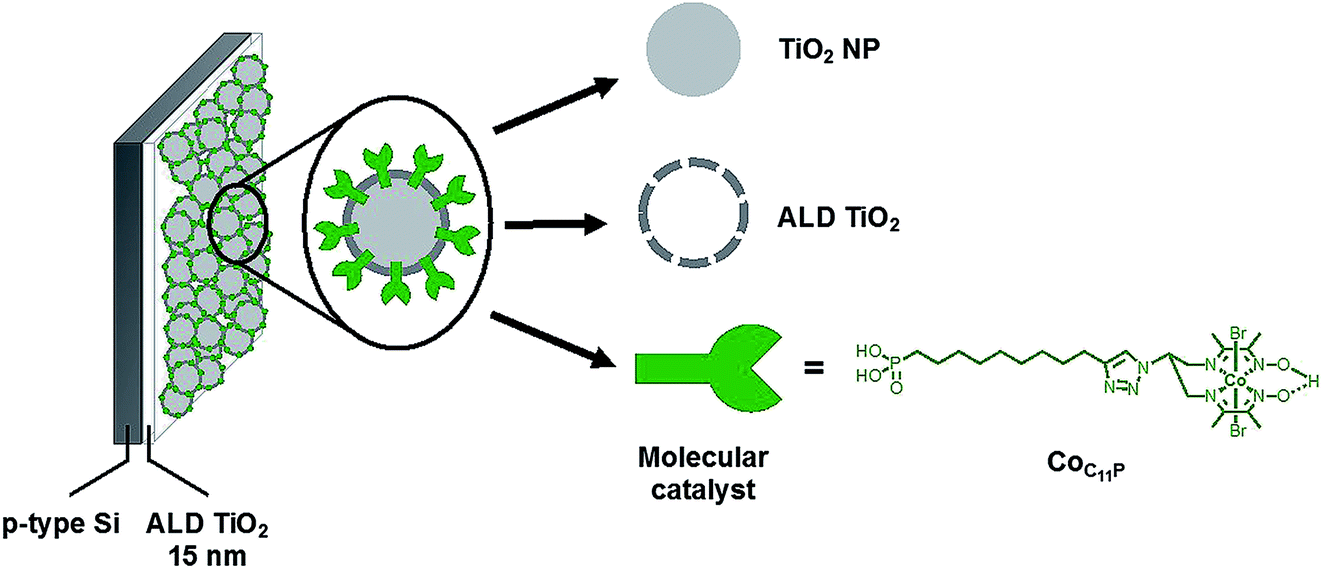 | ||
| Fig. 1 Molecular-engineered silicon photocathode for H2-evolution. | ||
Results and discussion
The native surface oxide layer of commercial boron-doped p-type silicon (100) wafers (725 μm-thick, resistivity 1–50 Ω cm) was removed using hydrofluoric acid (HF) (see the Experimental part for the detailed etching process). Then the p-Si electrodes were rapidly transferred to the chamber of an ALD system. The electrodes were coated with a first layer of TiO2 through 710 ALD cycles performed in continuous mode at 255 °C. Fig. 2A shows the top view scanning electron microscopy (SEM) image of this p-Si|ALD-TiO2 electrode, revealing a TiO2 layer for the protection of p-Si against corrosion in aqueous electrolytes. The thickness of the ALD-TiO2 layer measured by ellipsometry was ∼15 nm. A second layer of mesoporous TiO2 was then spin-coated (SC) on top of the first layer to increase the surface area of the electrode and thus afford higher catalyst loading. Fig. 2B and C show the top view and cross-sectional SEM images of p-Si|ALD-TiO2|SC-TiO2 electrodes, revealing a ∼300 nm thickness for the SC-TiO2 layer. We selected the diimine–dioxime cobalt complex (CoC11P) derivative containing a pendant phosphonic acid anchor as the H2-evolving molecular catalyst.26 Soaking the p-Si|ALD-TiO2|SC-TiO2 electrodes in a methanolic solution of CoC11P results in the straightforward immobilization of the complex. The grafting occurs through the formation of a mixed organic–inorganic phosphonate linkage,27 as evidenced by electrochemistry, X-ray photoelectron spectroscopy (XPS) and infrared spectroscopy (see below). To further stabilize the catalyst anchoring against hydrolysis during long term operation in aqueous electrolytes, we specifically undertook a second ALD process, inspired by the “Mummy” strategy.28 In this process, an ultra-thin overlayer of TiO2 is deposited at the mesoporous CoC11P-modified SC-TiO2 interface to shield the catalyst–surface linkage.28 We thus performed 10 ALD cycles in a 5 s exposure mode at 150 °C. The low deposition temperature was used to avoid potential degradation of the molecular structure of the catalyst while the selected exposure mode ensured that the ∼0.2 nm thick overlayer is uniformly deposited within the whole mesoporous layer of CoC11P-modified TiO2.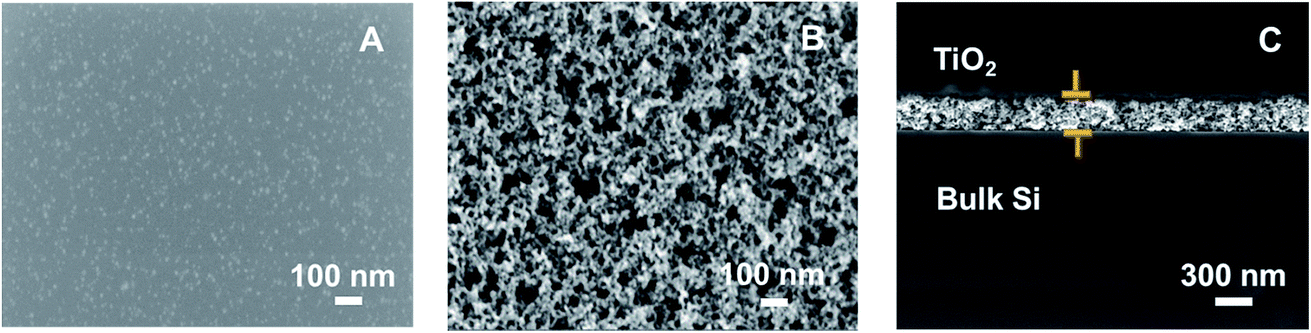 | ||
| Fig. 2 SEM images of TiO2 layers on p-Si: ALD-TiO2 (top view) (A) and ALD-TiO2/SC-TiO2 top view (B) and cross-sectional view (C). | ||
Fig. 3 shows the XPS spectra of the Co 2p core region of p-Si|ALD-TiO2|SC-TiO2|CoC11P (black trace) and p-Si|ALD-TiO2|SC-TiO2|CoC11P|ALD-TiO2 (red trace) electrodes. The peaks observed at 795.4 and 780.2 eV correspond to Co 2p1/2 and 2p3/2 core levels, respectively. The binding energies are similar to those previously reported for the same catalytic moiety bound to carbon nanotubes, NiO or ITO.22,25,26 The fact that the binding energies of the Co 2p peaks are not modified upon coating strongly suggests that this overlayer did not degrade the molecular structure of the CoC11P catalyst in p-Si|ALD-TiO2|SC-TiO2|CoC11P|ALD-TiO2 electrodes.
 | ||
| Fig. 3 X-ray photoelectron spectra of the Co 2p core region of the p-Si|ALD-TiO2|SC-TiO2|CoC11P electrode (black trace) and p-Si|ALD-TiO2|SC-TiO2|CoC11P|ALD-TiO2 electrode (red trace). | ||
A Fourier transform infrared (FTIR) spectrum was measured on the CoC11P-modified TiO2 material scratched from a p-Si|ALD-TiO2|SC-TiO2|CoC11P|ALD-TiO2 electrode and sampled as a KBr pellet. Fig. 4 compares the FTIR spectrum of this material (red trace) with that of the CoC11P molecular catalyst (black trace). Signals corresponding to the stretching frequencies of the oxime, imine and C–C bond in the imine–oxime moieties are found almost unchanged in both spectra at 1140/1146, 1519/1514 and 1251 cm−1, respectively (assignments made by comparison with the related cobaloxime compounds following ref. 29). The broad peak at ∼1625 cm−1 observed for the p-Si|ALD-TiO2|SC-TiO2|CoC11P|ALD-TiO2 electrode (red trace) corresponds to the bending vibration band of the hydrogen-bonded adsorbed water on unmodified TiO2 (blue trace, 1630 cm−1).30,31 This analysis further confirmed that the final 10 ALD cycles for TiO2 deposition at 150 °C did not degrade the molecular structure of the CoC11P catalyst.
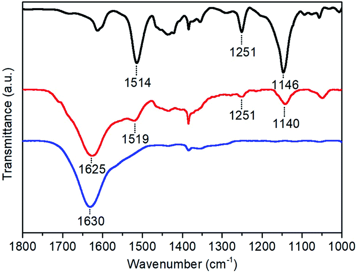 | ||
| Fig. 4 FTIR spectra of the CoC11P molecular catalyst as synthesized (black trace), p-Si|ALD-TiO2|SC-TiO2|CoC11P|ALD-TiO2 electrode (red trace) and unmodified TiO2 (blue trace). | ||
CoC11P loading on the p-Si|ALD-TiO2|SC-TiO2|CoC11P|ALD-TiO2 electrode was quantified by inductively coupled plasma atomic emission spectrometry (ICP-AES) after digestion of the ALD-TiO2|SC-TiO2|CoC11P|ALD-TiO2 layer in sulfuric acid. ICP-AES analysis indicated a Co loading of 67.4 ± 0.42 nmol cm−2. We, however, note that only a fraction of the grafted catalysts may be electrochemically addressable, as reported previously for similar catalyst-modified mesoporous conducting metal oxide electrodes.9,26
The photo-electrocatalytic properties of the p-Si|ALD-TiO2|SC-TiO2|CoC11P|ALD-TiO2 electrode for H2 evolution were assessed in degassed 1 M phosphate buffer (pH 7) under solar AM 1.5 irradiation in a three-electrode system. Negligible current densities were observed during linear sweep voltammetry (LSV, 10 mV s−1) under dark conditions for all the fabricated photocathodes (Fig. 5). Under illumination (1 sun AM 1.5), the LSV of the p-Si|ALD-TiO2|SC-TiO2|CoC11P|ALD-TiO2 electrode (Fig. 5, red trace) displays a current density of −1.25 mA cm−2 at 0 V vs. RHE and an onset photocurrent potential of +0.47 V vs. RHE (fill factor of 0.17). In comparison, the p-Si|ALD-TiO2|SC-TiO2|CoC11P electrode without the ALD-TiO2 overlayer displays much lower performances, with a threefold lower (−0.5 mA cm−2) current density at 0 V vs. RHE and an onset photocurrent potential of +0.09 V vs. RHE (Fig. 5, black trace). In both cases, the photovoltage provided at the p-Si/TiO2 results in catalysis, occurring from potentials significantly more positive than the redox potential of the CoII/CoI couple observed at ∼0 V vs. RHE for CoC11P-modified TiO2 electrodes deposited onto FTO (see Fig. S1†). The higher current density displayed by the p-Si|ALD-TiO2|SC-TiO2|CoC11P|ALD-TiO2 electrode compared to the same construction incorporating decylphosphonic acid C10P, as a surrogate reproducing surface modification through phosphonate binding, clearly evidences the role of CoC11P in catalyzing H2 evolution (Fig. S2†). The current density displayed by the p-Si|ALD-TiO2|SC-TiO2|CoC11P|ALD-TiO2 photocathode is one order of magnitude higher than that of a similar hybrid construction without ALD-TiO2 layers (p-Si|mesoTiO2|NiP).10 At the same time the onset potential is shifted 350 mV more positive. The significantly improved performance of the electrode functionalized with the 10 cycle ALD-TiO2 overlayer confirms that such an overlayer enables the sequestering of the CoC11P molecular catalyst within the mesoporous TiO2 layer where it can mediate H2 evolution.
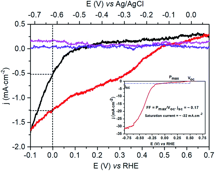 | ||
| Fig. 5 LSV (10 mV s−1) of the p-Si|ALD-TiO2|SC-TiO2|CoC11P electrode (magenta, resp. black trace) and p-Si|ALD-TiO2|SC-TiO2|CoC11P|ALD-TiO2 electrode (violet, resp. red trace) in 1 M phosphate buffer (pH 7) under dark conditions, respectively, one sun irradiation. The inset shows the p-Si|ALD-TiO2|SC-TiO2|CoC11P|ALD-TiO2 electrode (red trace) at more negative potentials and the calculated fill factor (FF). | ||
The superior behavior fostered by the ALD-TiO2 overlayer was further supported by chronoamperometric measurements performed for 1 hour at 0 V vs. RHE under similar conditions (Fig. 6).32 An initial decay of current, also observed in catalyst-free electrodes (Fig. S3†), might originate from the charging behavior at the silicon/TiO2 interface and/or within the n-type TiO2 semiconductor caused by the sudden illumination. Then, both electrodes exhibited stable current densities of the same magnitude as that measured during LSV experiments, i.e. −0.5 and −1.3 mA cm−2 for p-Si|ALD-TiO2|SC-TiO2|CoC11P and the overcoated p-Si|ALD-TiO2|SC-TiO2|CoC11P|ALD-TiO2 electrodes, respectively (Fig. 6, black and red traces, respectively). The chronoamperometric trace of the p-Si|ALD-TiO2|SC-TiO2|CoC11P|ALD-TiO2 electrode shows staggered variations due to the intermittent release of H2 bubbles from the electrode surface. Gas chromatography analysis quantified the production of 17.3 μmol cm−2 of H2, which evolved concomitantly with the passage of 3.96 C cm−2 through the p-Si|ALD-TiO2|SC-TiO2|CoC11P|ALD-TiO2 electrode, yielding a faradaic efficiency of 84%. With these data and the catalyst loading determined from ICP-AES, a turnover number (TON) of 260 and a turnover frequency (TOF) of 0.071 s−1 were calculated.
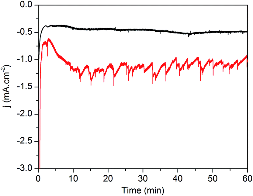 | ||
| Fig. 6 Chronoamperometric profiles of the p-Si|ALD-TiO2|SC-TiO2|CoC11P electrode (black trace) and p-Si|ALD-TiO2|SC-TiO2|CoC11P|ALD-TiO2 electrode (red trace) in 1 M phosphate buffer (pH 7) recorded at 0 V vs. RHE under one sun irradiation. | ||
We note that higher current densities are observed at more negative potentials (see the inset in Fig. 5) with a second photoinduced process starting at −0.25 V vs. RHE. This second process likely corresponds to H2 evolution directly mediated at the surface of TiO2 as it is also observed for the p-Si|ALD-TiO2|SC-TiO2 electrode at higher negative potential (Fig. S4†). Possibly the construction described here does not allow for sufficient catalyst loading (based on the intrinsic turnover frequency of each molecular catalyst) to sustain such high current densities. Alternatively, the electronic coupling between the Si wafer and the TiO2 layers may not be optimal to allow the catalyst layer to equilibrate with the conduction band of Si.
We also investigated the behaviour of the p-Si|ALD-TiO2|SC-TiO2|CoC11P|ALD-TiO2 electrodes in 0.1 M NaOH (pH 13) (Fig. S5†). From LSV measurements, the current density and onset photocurrent potential were measured as −1 mA cm−2 at 0 V vs. RHE and +0.53 V vs. RHE under solar AM 1.5 illumination, respectively. These figures indicate good H2-evolution properties of the CoC11P catalyst in basic aqueous electrolyte, in line with Turner's report on the catalytic activity of cobaloximes under similar conditions.6 Current densities similar to those observed in LSV were sustained during chronoamperometric measurements (0 V vs. RHE) at the p-Si|ALD-TiO2|SC-TiO2|CoC11P|ALD-TiO2 electrode in 0.1 M NaOH (pH 13) for a period of one hour under AM 1.5 solar irradiation (Fig. S6†), yielding a faradaic efficiency of 83%. TON and TOF were calculated to be 215 and 0.06 s−1, respectively, based on the catalytic loading determined through ICP-AES. XPS analysis of the Co 2p core region (Fig. S7†) carried out at the end of this chronoamperometry experiment supports the presence of the retained CoC11P molecular catalyst on the p-Si|ALD-TiO2|SC-TiO2|CoC11P|ALD-TiO2 electrode, with a Co 2p3/2 peak at 780.2 eV, similar to that in Fig. 3, whereas alteration of the Co complex would result in a shoulder peak around 782 eV.6,33 The noisiness of this feature indicates that the complex is present at the very surface of the mesoporous TiO2 layer with a decreased concentration compared to the as-prepared sample. By contrast, a system based on a similar diimine–dioxime catalyst attached on TiO2 shows full disappearance of the XPS Co 2p3/2 signature after activity.10 Retention of the Co 2p3/2 XPS binding energy after activity is another indication that the ALD-strategy is effective in stabilizing the grafting of the molecular catalyst during turn-over. These data show for the first time the versatility and stability of the CoC11P molecular catalyst and phosphonate anchor, respectively, which is operative over a wide range of pH values, paralleling a report on cobaloximes with carboxylate anchors by Turner and coworkers.6 Furthermore, working of photocathodes in basic aqueous electrolytes is of great interest since that would help to tether them with TiO2-based photoanodes in a tandem cell configuration for unbiased water splitting.
In both cases, relatively high photocurrent densities measured at 0 V vs. RHE result from the combination of an ALD-coated compact TiO2 underlayer protecting p-Si from corrosion, a mesoporous TiO2 layer allowing for high catalytic loading, and a second ALD-coated compact ultrathin TiO2 overlayer stabilizing the anchorage of the molecular catalyst onto the mesoporous layer. Our control experiments (Fig. S3†) demonstrate that all three components are crucial to achieve efficiency and stability: (i) the presence of a thin TiO2 protective layer allows generation of photocurrent in the mA cm−2 range for photoelectrodes stored in ambient atmosphere for days, (ii) the SC mesoporous TiO2 allows a 10-fold increase of the current density compared to a flat ALD-TiO2 surface (compare red and orange curves in Fig. S3b†), and (iii) the presence of an ALD-TiO2 overlayer results in a sustained photocurrent at its nominal value measured during LSV. This result is particularly remarkable since the non-stabilized grafting of a similar diimine–dioxime cobalt catalyst led to rapid leaching of the catalyst from the mesoporous TiO2 layer (30 min, <2 TONs achieved),10 while the ALD-coated TiO2 overlayer of this study allowed a sustained TOF (260 TONs achieved within 1 h with stable current density) for H2 evolution by the molecular catalyst. With such an optimized platform we offer the possibility of using cost-effective silicon wafers for the preparation of hybrid photocathodes displaying performances previously restricted to expensive III–V semiconductors such as GaP7,8 or GaInP2.6
Conclusion
We successfully designed a stable photocathode platform that unlocks the exploitation of cost-effective and technology-ready silicon wafers for the construction of robust photocathodes exclusively based on Earth-abundant elements, as an asset for sustainability. ALD and sol–gel coating techniques, which we used in our strategy, are currently deployed for various industrial applications, en route for the future scaling up of the production of such photoelectrodes. The assets of this photocathode architecture are resistance to corrosion, high catalyst loading and retention of the molecular structure of the catalyst on the electrode surface. These assets result in a platform suitable to anchor various molecular catalysts onto inorganic semiconductors in future research on (photoelectro)catalysis. Reaching the current density displayed by high-performing semiconductors by improving the loading densities in molecular catalysts at hybrid electrodes is currently being investigated in our laboratory and could benefit from the hierarchical inverse opal TiO2 structures recently developed for photoelectrochemical biological systems.34Experimental
Chemicals
Hydrofluoric acid (HF, 48%), solvents and starting materials were purchased from Sigma Aldrich. Ultrapure nitric acid (65%) for ICP-AES analysis was purchased from Chem-Lab. CoC11P was prepared as previously described.26 Decylphosphonic acid (C10P) was purchased from Sigma-Aldrich.ALD of TiO2 on the silicon surface (p-Si|ALD-TiO2)
Boron doped p-type silicon with a resistivity of 1–50 ohm cm, orientation 100, thickness 725 μm and diameter 200 mm was bought from MEMC. The silicon was cut into 0.5 × 0.5 cm pieces and etched with 1![[thin space (1/6-em)]](https://www.rsc.org/images/entities/char_2009.gif) :1 HF:ethanol mixture for 10 min. It was then stored in an argon degassed heptane solution and dried under argon before transferring into the ALD chamber. TiO2 was deposited using an ALD system (Savannah 100 ALD system, Cambridge Nano Tech Inc.) with a precursor temperature at 95 °C, pump line temperature at 150 °C and sample chamber temperature at 255 °C in continuous mode for 710 cycles with a nitrogen flow of 5 sccm. The precursors used for TiO2 deposition were titanium(IV) isopropoxide (TTIP) purchased from Strem Chemicals Inc. and water as sources for titanium and oxygen, respectively. A cycle typically comprised a 0.5 s TTIP pulse and a 0.02 s water pulse with a 5 s purging time in between.
:1 HF:ethanol mixture for 10 min. It was then stored in an argon degassed heptane solution and dried under argon before transferring into the ALD chamber. TiO2 was deposited using an ALD system (Savannah 100 ALD system, Cambridge Nano Tech Inc.) with a precursor temperature at 95 °C, pump line temperature at 150 °C and sample chamber temperature at 255 °C in continuous mode for 710 cycles with a nitrogen flow of 5 sccm. The precursors used for TiO2 deposition were titanium(IV) isopropoxide (TTIP) purchased from Strem Chemicals Inc. and water as sources for titanium and oxygen, respectively. A cycle typically comprised a 0.5 s TTIP pulse and a 0.02 s water pulse with a 5 s purging time in between.
SC of mesoporous TiO2 on the ALD-TiO2 deposited silicon surface (p-Si|ALD-TiO2|SC-TiO2)
A suspension of TiO2 anatase nanoparticles of size 15–20 nm (Ti-Nanoxide T300/SC, Solaronix) was spin-coated on ALD-TiO2 deposited on silicon (polished side). The spin-coating was carried out at 5000 rpm for 30 s, with an acceleration of 2000 rpm s−1. The coated electrodes were then thermally treated at 475 °C for 30 min in a tubular furnace under an argon flow.Immobilization of the CoC11P molecular catalyst and C10P molecular anchor on the TiO2 coated silicon surface (p-Si|ALD-TiO2|SC-TiO2|CoC11P and p-Si|ALD-TiO2|SC-TiO2|C10P)
A saturated solution of CoC11P molecular catalyst26 was prepared with methanol. Silicon substrates coated with ALD-TiO2 and mesoporous SC-TiO2 were soaked overnight in the catalyst solution. The substrates were then washed with methanol before further modification. A similar procedure was followed to sensitize the electrode with the C10P molecular anchors.ALD-TiO2 deposition on the CoC11P molecular catalyst immobilized TiO2 coated silicon surface (p-Si|ALD-TiO2|SC-TiO2|CoC11P|ALD-TiO2)
CoC11P-functionalized TiO2-modified silicon electrodes were coated with 10 cycles of ALD-TiO2. ALD was performed in exposure mode with an exposure time of 5 s. During the exposure, pumping on the chamber is stopped in order to allow time for the precursors to diffuse in the mesoporous TiO2 layer. Except for the temperature of the deposition chamber which was decreased from 255 °C to 150 °C to avoid degradation of the catalysts, the other parameters (temperature, nitrogen flow, pulse duration and purging time) were kept the same as in continuous mode.Preparation of TiO2–CoC11P electrodes
Screen-printed TiO2 substrates were purchased from Solaronix. The electrodes were sintered under atmospheric conditions in a Harry Gestigkeit flat furnace operated with a Detflef Gestigkeit-Programmer PR5 control board programmed with the following temperature ramp: R.T. to 450 °C (30 min), 30 min at 450 °C. The thickness of the TiO2 layer is ca. 600 nm. The substrates were cooled to ca. 90 °C and introduced in PTFE boxes containing 10 mL of a 0.5 mM methanolic solution with CoC11P (5 μmol). The boxes were closed and the content was stirred for 24 h on an orbital stirring plate. The electrodes were removed from the solution, washed by dipping them in pristine methanol for 10 min under orbital stirring and dried with N2, to yield the decorated TiO2/CoC11P electrodes.Instrumental characterization techniques
A Zeiss Ultra+ instrument was used for SEM imaging of ALD-TiO2 and mesoporous SC-TiO2 in In-Lens mode at accelerating voltages of 20 kV and 2 kV, respectively.An ellipsometer (M 2000 model) from J. A. Woollam Co., In. was used to measure the thickness of the ALD-TiO2 substrate, using the CompleteEASE software (V4.72). It was used in the “off-sample” configuration with an incident angle of attack of 75° with respect to the film plane normal, and the light wavelength was scanned between 200 nm and 1700 nm. The obtained data were fitted with the CompleteEASE software (V4.72). A typical example of the recorded spectrum and its fit are displayed in Fig. S8.†
FTIR spectra were recorded on a Perkin-Elmer Spectrum 100 spectrometer. The spectra were collected over 64 scans, with a resolution of 1 cm−1 and background corrected with an ambient atmosphere spectrum. Spectra of the samples were recorded and analyzed using SPECTRUM version 10.5.2 software, in the range of 1000–2000 cm−1. The powdered samples were mixed in KBr and pressed to form pellets. Typically, the pellets were made of the scratched overlayer of the electrode (4 cm2) mixed with 100 mg of KBr.
XPS analyses were carried out with a Versa Probe II spectrometer (ULVAC-PHI) equipped with a monochromated Al Kα source (hν = 1486.6 eV). The core level peaks were recorded with a constant pass energy of 23.3 eV. The XPS spectra were fitted with CasaXPS 2.3.15 software using Shirley background and a combination of Gaussian (70%) and Lorentzian (30%) distributions. Binding energies are referenced with respect to the adventitious carbon (C 1s BE = 284.6 eV).
ICP-AES samples were analyzed using a Shimadzu ICPE-9000 instrument with a mini plasma torch in axial reading mode. The sample preparation involves the digestion of the p-Si|ALD-TiO2|SC-TiO2|CoC11P|ALD-TiO2 electrode (22.5 cm2 area) in 10 mL of 98% sulfuric acid at 60 °C for one hour under sonication. The solution was then diluted to 30 mL with 1% ultrapure nitric acid solution prepared with MilliQ water and sonicated for 5 hours. Further, 1.67 mL of this solution was diluted to 10 mL with 1% ultrapure nitric acid prepared with MilliQ water. This final solution (10 mL) was analyzed for cobalt concentration by ICP-AES. The samples were prepared in triplicate.
Photocurrent and microGC measurements
Electrochemical analysis was performed using a BioLogic SP300 bipotentiostat and a representative three-electrode setup. A platinum wire was used as the auxiliary electrode and Ag/AgCl, KCl (3 M) (denoted as Ag/AgCl) as the reference electrode bridged to the electrolyte through a Vycor frit. The unpolished side of silicon was cotton swabbed with an In–Ga eutectic mixture and superposed with a copper plate. The electrical connection was made through the copper plate. Photoelectrodes were front-illuminated with a 300 W ozone-free xenon lamp (Newport) operated at 280 W coupled to an AM 1.5 filter. Irradiance at the substrate surface was measured to be 100 mW cm−2 using a Newport PM1918-R power meter.Calibration of the reference electrode was realized with [K4Fe(CN)6] in 0.1 M potassium phosphate buffer at pH 7 (ref. 35) and conversion of potentials against the normal hydrogen electrode (NHE) and the reversible hydrogen electrode (RHE) was performed as previously described.36
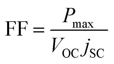
Fill factor calculation:37
A MicroGC S3000 (SRA Instruments) with a diamond LV Ms5A 14m module was operated via a Soprane chrome interface. Throughout the chronoamperometric run, argon gas was purged into the electrolyte at a flow rate of 5 mL min−1 controlled with a mass flow controller, and the outlet gas mixture was analyzed using a microGC.
Conflicts of interest
There are no conflicts to declare.Acknowledgements
This work was supported by the French National Research Agency (Labex program ARCANE – ANR-11-LABX-0003-01 and ANR-17-EURE-0003).References
- M. G. Walter, E. L. Warren, J. R. McKone, S. W. Boettcher, Q. Mi, E. A. Santori and N. S. Lewis, Chem. Rev., 2010, 110, 6446–6473 CrossRef CAS PubMed.
- N. Armaroli and V. Balzani, ChemSusChem, 2011, 4, 21–36 CrossRef CAS PubMed.
- N. Armaroli and V. Balzani, Energy Environ. Sci., 2011, 4, 3193–3222 RSC.
- J. R. McKone, N. S. Lewis and H. B. Gray, Chem. Mater., 2014, 26, 407–414 CrossRef CAS.
- D. Zhang, J. Shi, W. Zi, P. Wang and S. Liu, ChemSusChem, 2017, 10, 4324–4341 CrossRef CAS PubMed.
- J. Gu, Y. Yan, J. L. Young, K. X. Steirer, N. R. Neale and J. A. Turner, Nat. Mater., 2015, 15, 456 CrossRef PubMed.
- A. M. Beiler, D. Khusnutdinova, S. I. Jacob and G. F. Moore, Ind. Eng. Chem. Res., 2016, 55, 5306–5314 CrossRef CAS.
- D. Khusnutdinova, A. M. Beiler, B. L. Wadsworth, S. I. Jacob and G. F. Moore, Chem. Sci., 2017, 8, 253–259 RSC.
- B. L. Wadsworth, A. M. Beiler, D. Khusnutdinova, S. I. Jacob and G. F. Moore, ACS Catal., 2016, 6, 8048–8057 CrossRef CAS.
- J. J. Leung, J. Warnan, D. H. Nam, J. Z. Zhang, J. Willkomm and E. Reisner, Chem. Sci., 2017, 8, 5172–5180 RSC.
- S. Chandrasekaran, T. Nann and N. H. Voelcker, Nano Energy, 2015, 17, 308–322 CrossRef CAS.
- S. Hu, N. S. Lewis, J. W. Ager, J. Yang, J. R. McKone and N. C. Strandwitz, J. Phys. Chem. C, 2015, 119, 24201–24228 CrossRef CAS.
- B. Seger, T. Pedersen, A. B. Laursen, P. C. K. Vesborg, O. Hansen and I. Chorkendorff, J. Am. Chem. Soc., 2013, 135, 1057–1064 CrossRef CAS PubMed.
- Y. W. Chen, J. D. Prange, S. Dühnen, Y. Park, M. Gunji, C. E. D. Chidsey and P. C. McIntyre, Nat. Mater., 2011, 10, 539 CrossRef CAS PubMed.
- C. C. L. McCrory, S. Jung, I. M. Ferrer, S. M. Chatman, J. C. Peters and T. F. Jaramillo, J. Am. Chem. Soc., 2015, 137, 4347–4357 CrossRef CAS PubMed.
- M. R. Nellist, F. A. Laskowski, F. Lin, T. J. Mills and S. W. Boettcher, Acc. Chem. Res., 2016, 49, 733–740 CrossRef CAS PubMed.
- H. Gerischer, J. Electroanal. Chem. Interfacial Electrochem., 1977, 82, 133–143 CrossRef CAS.
- F. D. Lin and S. W. Boettcher, Nat. Mater., 2014, 13, 81–86 CrossRef CAS PubMed.
- S. Hennessey and P. Farras, Chem. Commun., 2018, 54, 6662–6680 RSC.
- N. Coutard, N. Kaeffer and V. Artero, Chem. Commun., 2016, 52, 13728–13748 RSC.
- N. Queyriaux, N. Kaeffer, A. Morozan, M. Chavarot-Kerlidou and V. Artero, J. Photochem. Photobiol., C, 2015, 25, 90–105 CrossRef CAS.
- E. S. Andreiadis, P. A. Jacques, P. D. Tran, A. Leyris, M. Chavarot-Kerlidou, B. Jousselme, M. Matheron, J. Pecaut, S. Palacin, M. Fontecave and V. Artero, Nat. Chem., 2013, 5, 48–53 CrossRef CAS PubMed.
- N. Kaeffer, M. Chavarot-Kerlidou and V. Artero, Acc. Chem. Res., 2015, 48, 1286–1295 CrossRef CAS PubMed.
- S. Donck, J. Fize, E. Gravel, E. Doris and V. Artero, Chem. Commun., 2016, 52, 11783–11786 RSC.
- N. M. Muresan, J. Willkomm, D. Mersch, Y. Vaynzof and E. Reisner, Angew. Chem., Int. Ed., 2012, 51, 12749–12753 CrossRef CAS PubMed.
- N. Kaeffer, C. D. Windle, R. Brisse, C. Gablin, D. Léonard, B. Jousselme, M. Chavarot-Kerlidou and V. Artero, Chem. Sci., 2018, 9, 6721–6738 RSC.
- S. P. Pujari, L. Scheres, A. T. M. Marcelis and H. Zuilhof, Angew. Chem., Int. Ed., 2014, 53, 6322–6356 CrossRef CAS PubMed.
- A. M. Lapides, B. D. Sherman, M. K. Brennaman, C. J. Dares, K. R. Skinner, J. L. Templeton and T. J. Meyer, Chem. Sci., 2015, 6, 6398–6406 RSC.
- P. E. Rutherford and D. A. Thornton, Spectrochim. Acta, Part A, 1979, 35, 711–714 CrossRef.
- H. Jensen, A. Soloviev, Z. Li and E. G. Søgaard, Appl. Surf. Sci., 2005, 246, 239–249 CrossRef CAS.
- A. Litke, Y. Su, I. Tranca, T. Weber, E. J. M. Hensen and J. P. Hofmann, J. Phys. Chem. C, 2017, 121, 7514–7524 CrossRef CAS PubMed.
- See Fig. S3† for control data on electrodes lacking the CoC11P catalyst or containing decyl phosphonic acid (C10P).
- S. Cobo, J. Heidkamp, P.-A. Jacques, J. Fize, V. Fourmond, L. Guetaz, B. Jousselme, V. Ivanova, H. Dau, S. Palacin, M. Fontecave and V. Artero, Nat. Mater., 2012, 11, 802–807 CrossRef CAS PubMed.
- D. H. Nam, J. Z. Zhang, V. Andrei, N. Kornienko, N. Heidary, A. Wagner, K. Nakanishi, K. P. Sokol, B. Slater, I. Zebger, S. Hofmann, J. C. Fontecilla-Camps, C. B. Park and E. Reisner, Angew. Chem., Int. Ed., 2018, 57, 10595–10599 CrossRef CAS PubMed.
- J. E. O'Reilly, Biochim. Biophys. Acta, 1973, 292, 509–515 CrossRef.
- N. Kaeffer, J. Massin, C. Lebrun, O. Renault, M. Chavarot-Kerlidou and V. Artero, J. Am. Chem. Soc., 2016, 138, 12308–12311 CrossRef CAS PubMed.
- D. Bartesaghi, I. D. Perez, J. Kniepert, S. Roland, M. Turbiez, D. Neher and L. J. A. Koster, Nat. Commun., 2015, 6, 7083 CrossRef CAS PubMed.
Footnotes |
| † Electronic supplementary information (ESI) available. See DOI: 10.1039/c8sc05006f |
| ‡ Present address: Department of Chemistry and Applied Biosciences, Vladimir Prelog Weg 1-5, ETH Zürich, CH-8093 Zürich, Switzerland. |
| This journal is © The Royal Society of Chemistry 2019 |