 Open Access Article
Discrimination between two memory channels by molecular alloying in a doubly bistable spin crossover material†
Francisco Javier
Valverde-Muñoz
a,
Maksym
Seredyuk
 *ab,
Manuel
Meneses-Sánchez
a,
M. Carmen
Muñoz
 c,
Carlos
Bartual-Murgui
a and
José A.
Real
 *a
*a
aDepartament de Química Inorgànica, Institut de Ciència Molecular (ICMol), Universitat de València, Valencia, Spain. E-mail: jose.a.real@uv.es
bOn leave from Department of Chemistry, Taras Shevchenko National University of Kyiv, 64/13, Volodymyrska Street, 01601, Kyiv, Ukraine. E-mail: mcs@univ.kiev.ua; mlseredyuk@gmail.com
cDepartament de Física Aplicada, Universitat Politècnica de València, Camino de Vera s/n, E-46022, Valencia, Spain
First published on 22nd February 2019
Abstract
A multistable spin crossover (SCO) molecular alloy system [Fe1−xMx(nBu-im)3(tren)](P1−yAsyF6)2 (M = ZnII, NiII; (nBu-im)3(tren) = tris(n-butyl-imidazol(2-ethylamino))amine) has been synthesized and characterized. By controlling the composition of this isomorphous series, two cooperative thermally induced SCO events featuring distinct critical temperatures (Tc) and hysteresis widths (ΔTc, memory) can be selected at will. The pristine derivative 100As (x = 0, y = 1) displays a strong cooperative two-step SCO and two reversible structural phase transitions (PTs). The low temperature PTLT and the SCO occur synchronously involving conformational changes of the ligand's n-butyl arms and two different arrangements of the AsF6− anions [T1c = 174 K (ΔT1c = 17 K), T2c = 191 K (ΔT2c = 23 K) (scan rate 2 K min−1)]. The high-temperature PTHT takes place in the high-spin state domain and essentially involves rearrangement of the AsF6− anions [TPTc = 275 K (ΔTPTc = 16 K)]. This behavior strongly contrasts with that of the homologous 100P [x = 0, y = 0] derivative where two separate cooperative one-step SCO can be selected by controlling the kinetics of the coupled PTLT at ambient pressure: (i) one at low temperatures, Tc = 122 K (ΔTc = 9 K), for temperature scan rates (>1 K min−1) (memory channel A) where the structural modifications associated with PTLS are inhibited; (ii) the other centered at Tc = 155 K (ΔTc = 41 K) for slower temperature scan rates ≤0.1 K min−1 (memory channel B). These two SCO regimes of the 100P derivative transform reversibly into the two-step SCO of 100As upon application of hydrostatic pressure (ca. 0.1 GPa) denoting the subtle effect of internal chemical pressure on the SCO behavior. Precise control of AsF6− ↔ PF6− substitution, and hence of the PTLT kinetics, selectively selects the memory channel B of 100P when x = 0 and y ≈ 0.7. Meanwhile, substitution of FeII with ZnII or NiII [x ≈ 0.2, y = 0] favors the low temperature memory channel A at any scan rate. This intriguing interplay between PT, SCO and isomorphous substitution was monitored by single crystal and powder X-ray diffractometries, and magnetic and calorimetric measurements.
Introduction
Responsive switchable materials attract great attention due to affording excellent study examples for understanding the mechanisms of phase transitions (PTs) and provide application prospects for future and emerging technologies.1 Some of the most investigated switchable molecular materials are pseudo-octahedral FeII spin-crossover (SCO) complexes, reversibly altering the high-spin (HS, t42ge2g) and low-spin (LS, t62ge0g) electronic states by the action of physicochemical stimuli (temperature, pressure, light and chemical substrates). The LS–HS conversion involves an electron transfer between the eg and t2g orbitals strongly coupled with structural changes in the coordination core of the FeII centres, which essentially affect Fe–ligand bond lengths and angles, and in turn the molecular conformation. In favourable cases these changes propagate cooperatively in the crystal, conferring bistability (memory) to the magnetic, optical, dielectric, structural and mechanical properties.2New developments in this area are crucial not only for elucidating background mechanisms behind observed properties and understanding the fundamental aspects of the SCO behaviour, but also for opening new perspectives in the field, such as the use of SCO compounds for creation of fully controllable “smart” materials responding to external stimuli in a desired way.3 For example, SCO can be combined with other relevant functions such as fluorescence,3c,4 electroluminescence,3e electronic transport5 and non-linear optical response6 thereby transferring its intrinsic bistable nature to the second property resulting in multifunctional materials that can be processed at different levels, from bulk to nanoscale.7
The control of the SCO characteristics, i.e. critical temperature and hysteresis width, remains one of the key focuses in the field. Tackling this problem by chemical methods requires engineering both the coordination site of the SCO centres and the cohesive elastic interactions between them through supramolecular and/or polymeric approaches. Furthermore, the strong sensitivity of the SCO behaviour to subtle changes in the elastic interactions makes it possible to control the SCO through crystal lattice rearrangements. In this respect, isomorphous substitution of SCO metal centres/complexes with non-SCO metal ions8/non-SCO complexes9 is an effective means to modulate the SCO behaviour. For example, substantial dilution with passive NiII or ZnII-based complexes breaks cooperativity between SCO centres and brings on a considerable downward shift of the SCO equilibrium/critical temperature T1/2/Tc, while low concentrations of the dopant can fine tune the SCO behavior.2d Metal dilution is a particular case of a more general concept of a solid solution of molecules, also known as molecular alloys, consisting in precise control of the stoichiometry of mixed ionic or molecular components during the synthetic step. This offers an unrivalled tool for optimization of desired magnetic, optical or electrical properties, as demonstrated by examples from adjacent fields,10 and for a few SCO systems.3a Another relevant strategy, yet little explored, is based on the possibility of controlling the SCO properties by a PT.11 It has been demonstrated for several systems that changes in the interaction binding between the components of the crystal due to a solid–solid or solid–liquid/liquid crystal PT may be sufficient for altering the spin state.11b,12
In this context, the complex [Fe(nBu-im)3(tren)](PF6)2 ((nBu-im)3(tren) = tris(n-butyl-imidazol(2-ethylamino))amine) affords an uncommon example of thermal hysteretic SCO behaviour deeply influenced by a synchronous symmetric crystallographic PT, leading to a reorganization of the crystal lattice due to significant conformational changes of the alkyl groups and displacement and rotation of the PF6− anions, taking place during the LS ↔ HS conversion.11b Playing with the slow kinetics featuring this PT, two well separate hysteretic thermally induced SCO behaviors (two memory channels) were found.11b Thus, high-temperature sweep rates (≥2 K min−1) quench the crystallographic PT thereby stabilizing channel A, which is characterized by a cooperative SCO, between the phases HS1 and LS1, centred at 122 K with a hysteresis 14 K wide. In contrast, low temperature-sweep rates (≤0.1 K min−1) stabilize channel B, characterized by a much more cooperative SCO, between the HS1 and LS2 phases, centred at ca. 155.5 K featuring a hysteresis loop 41 K wide (see Scheme 1). The phases display different arrangement 1 and arrangement 2 of the flexible butyl groups and of the anions. Furthermore, the LS1 phase affords an uncommon very long-lived photogenerated HS1* phase after light irradiation at 80 K. The very slow relaxation kinetics is controlled by conformational rearrangements of the butyl groups during the HS1* → LS1 transformation.11f
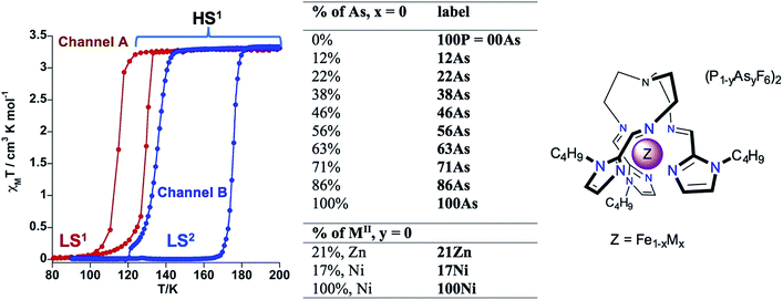 | ||
| Scheme 1 Description of the SCO behavior of 100P. [Fe1−xMx(nBu-im)3(tren)](P1−yAsyF6)2 system (M = Ni, Zn). | ||
In order to understand more in depth the correlation between SCO and structural PTs in 100P and find reliable chemical means to discriminate between the two thermal memory channels, we have investigated the isostructural compound [Fe(nBu-im)3(tren)](AsF6)2 (100As) and the solid solutions [Fe1−xMx(nBu-im)3(tren)](P1−yAsyF6)2 (see Scheme 1). Herein, we show that the SCO behavior of 100P (x = 0; y = 0) is highly sensitive to application of external hydrostatic low pressure and, consequently, the resulting SCO behavior is similar to that of 100As (x = 0; y = 1) which also displays double bistability due to SCO and PTs but at higher temperatures. Furthermore, modulating the internal “chemical pressure” built up by partial substitution of FeII with MII (xM, x < 100 and y = 0, M = Zn, Ni) or P with As (yAs, x = 0 and y < 100) leads to effective discrimination of the two memory channels resulting from the interplay of the SCO and a PT in the pure 100P.
Results
SCO properties of 100As
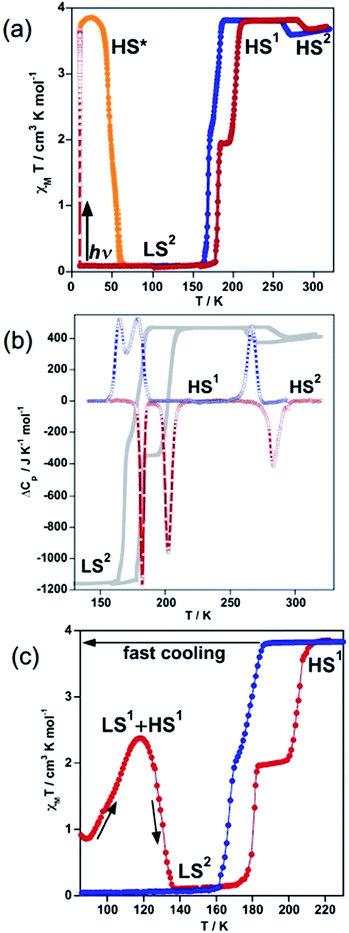
The magnetic behaviour of 100As, recorded at 1 K min−1 between 10 and 300 K, is shown in Fig. 1a in the form of χMT vs. T (χM is the molar magnetic susceptibility and T is the temperature). At 300 K, the χMT value is close to 3.68 cm3 K mol−1 as expected for an FeII compound in the HS state (S = 2). On cooling a gradual decrease of the χMT value down to 3.56 cm3 K mol−1 is followed by a limited but abrupt jump up to 3.80 cm3 K mol−1. This bistable behaviour is associated with a reversible crystallographic PT within the HS phase [HS1 ↔ HS2] (vide infra).The shaped hysteresis is centred at TPTc = 276 K with the loop width ΔTPTc = 17 K. Further cooling does not reveal any marked evolution of χMT down to 188 K, where an abrupt two-step decrease down to zero value is detected (S = 0) with a well-defined plateau of the ascending curve at 50% conversion upon subsequent heating. The two steps centred at T1c = 175 K and T2c = 193 K are characterised by a hysteresis loop ΔT1c = 14 K and ΔT2c = 23 K wide, respectively. In opposite to 100P, no remarkable kinetic effects were observed for the range of temperature-sweeping rates 4–0.5 K min−1 in the magnetic response of 100As (Fig. S1†). However, when cooling from 300 K to 80 K in ca. 15 s (≈900 K min−1) partial thermal trapping of the sample was observed (Fig. 1c). At 80 K the χMT value of the trapped sample is ca. 1 cm3 K mol−1 and upon heating at 0.3 K min−1 it increases to reach a maximum value of 2.37 cm3 K mol−1 at 120 K, which corresponds to ca. 62% of the FeII centres in the HS state. Then, at higher temperatures the compound relaxes back to the LS state and upon further heating it reaches the HS state. As a hypothesis and by similarity with 100P the trapped state could be a mixture of the states LS1 and HS1 and the LS state attained after relaxation should correspond to the LS2 phase (vide infra).
Quantitative photo-generation of the metastable HS* state at low temperature, the so-called light induced excited spin state trapping (LIESST) experiment,13 was carried out at 10 K by irradiating a microcrystalline sample (0.75 mg) of 100As with red light (λ = 633 nm) for over 3 h. Further heating of the sample in the photo-stationary HS* state in the dark at 0.3 K min−1 uncovers a two-step LIESST relaxation process with TLIESST1 = 45 K and TLIESST2 = 57 K (Fig. 1a) relevant to the two-step thermal SCO.
Differential scanning calorimetry (DSC) measurements were carried out for 100As in the cooling and heating modes to support the magnetic bistability data and quantify the thermodynamic parameters associated with the SCO and PT. The corresponding anomalous variation of the heat capacity ΔCpvs. T plots is depicted in Fig. 1b overlaid with the magnetic data. Upon cooling/heating three processes are detected at critical temperatures T1c = 174 K (ΔT1c = 17 K), T2c = 191 K (ΔT2c = 23 K) and TPTc = 275 K (ΔTPTc = 16 K) confirming the reversibility of the two-step SCO process and of the PT. The enthalpy and entropy changes of the PT averaged over both runs, ΔHPT = 3.94 kJ mol−1 and ΔSPT = 14.29 J K−1 mol−1, account for the substantial rearrangements associated with order/disorder events of the butyl groups and the anions (vide infra). The averaged enthalpy and entropy for the two low temperature peaks, ΔHSCO = 10.3 kJ mol−1 and ΔSSCO = 59.5 J K−1 mol−1, respectively, exceed values reported for each of the two transitions LS ↔ HS in 100P [ΔHSCO(LS1 ↔ HS1) = 5.2 kJ mol−1 and ΔSSCO(LS1 ↔ HS1) = 41.6 J K−1 mol−1; ΔHSCO(LS2 ↔ HS1) = 6.8 kJ mol−1 and ΔSSCO(LS2 ↔ HS1) = 39.5 J K−1 mol−1].11b
SCO properties of 100P under pressure
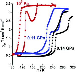
The SCO properties of 100P (channel A and channel B) and 100As differ in critical temperatures, hysteresis width and more notably in nature (one or two step). The observed 30 K upward shift of the average critical temperature when replacing PF6− with AsF6− suggests the introduction of additional chemical pressure in 100As as a result of the slightly larger ionic radius of As. To support this hypothesis, we have investigated the effect of small applied hydrostatic pressure on the SCO behaviour of 100P. At ambient pressure, in the cooling mode (1 K min−1), 100P displays essentially the behaviour of channel A. At a pressure of 0.11 GPa the SCO shifts upwards by 100 K, and, surprisingly, it becomes two-step with critical temperatures centred at T1c = 221 K and T2c = 251 K, characterised by a hysteresis loop ΔT1c = 13 K and ΔT2c = 39 K, respectively, and a well-defined intermediate plateau on heating as shown in Fig. 2. This SCO is practically that of 100As at ambient pressure. Increasing pressure up to 0.14 GPa shifts the transition to higher temperatures (T1c = 245 K, ΔT1c = 13 K and T2c = 285 K, ΔT2c = 36 K). Interestingly, these results demonstrate very similar effects on the SCO of the complex cation whatever the nature of the applied pressure, i.e. external or “internal” generated by PF6− ↔ AsF6− anion substitution. A second relevant finding is the hypersensitivity of 100P towards imposed external pressure with dependence d〈Tc〉/dp ≈ 1000 K/GPa, where 〈Tc〉 = (Tc1 + Tc2)/2, although the regularly observed value lies in the range of 150–200 K/GPa (ref. 14) (Fig. S2†).Study of [Fe1−xMx(nBu-im)3(tren)](P1−yAsyF6)2 molecular alloys
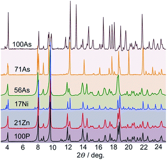
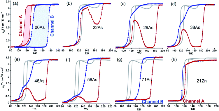
The high sensitivity of the SCO properties of 100P to external hydrostatic pressure, also apparent when internal “chemical pressure” increases when replacing PF6− with AsF6−, prompted us to study solid solutions based on anion (PF6− → AsF6−) and metal (FeII → MII) substitution. A series of solid solutions were prepared in the same way as 100P and 100As but containing mixtures of PF6− and AsF6− anions in a calculated ratio. It was found that the PXRD profiles of 22As–56As, as well as of 21Zn and 17Ni, are indistinguishable from that of 100P (Fig. 3). On the other hand, for 71As, a shift/coalescence of diffraction peaks is observed in the high angle range, in addition to the change of peak intensity, although in the low angle range the diffraction patterns perfectly match that of 100P. These findings are consistent with the evolution of the magnetic properties on isostructural substitution in the aforementioned series.Gradual substitution of PF6− with AsF6− anions continuously reshapes the original SCO behaviour of 100P stabilizing a phase which compares well with channel B. This is illustrated in Fig. 4b–g where the SCO of pristine 100P, recorded at scan rate 2 K min−1, is also included for comparison (grey line). For 22As, channel A is prevailing and a low temperature hysteresis is still observed but an increase of the relaxation rate favouring channel B is obvious (Fig. 4b). Increasing the concentration of AsF6− in 29As, 38As, 46As and 56As progressively accelerates relaxation and suppresses channel A in favour of channel B, which finally in 71As produces a single-step hysteresis loop centred at Tc = 171 K with ΔTc = 34 K. Further increase of AsF6− affords compound 86As that gives rise to a narrow two-step SCO similar to that of the pristine 100As (Fig. S3†). It is worth mentioning that the PT within the HS phase HS1 ↔ HS2 increases in amplitude and decreases in temperature as the amount of AsF6− increases in the molecular alloy (see Fig. S4†).
Interestingly, stabilization of channel A is achieved by partial substitution above a certain threshold value of FeII with ZnII or NiII, i.e. y ≥ 0.21 for ZnII or y ≥ 0.17 for NiII. The resulting isostructural solid solutions 21Zn or 17Ni display one step cooperative SCO with critical temperatures centred at Tc = 117 and 121 K, characterized by ΔTc = 7 and 3 K wide hysteresis loops, respectively, at any rate down to 0.5 K min−1 (Fig. 4h, for 17Ni see also Fig. S5†). The pure compound 100Ni shows a constant susceptibility value of χMT ≈ 1.2 cm3 K mol−1 in the temperature range 50–300 K without any irregularities (Fig. S6†).
It is worth noting that despite the clear kinetic stabilization of channel B for 71As, thermal quenching allows trapping the sample into the hidden channel A. For example, after cooling 71As from 300 K to 80 at ca. 800 K min−1 the χMT value is essentially that of the FeII in the LS state (0.22 cm3 K mol−1) (see Fig. 5). Then, when heating at 0.3 K min−1, χMT increases to attain a value of 3.20 cm3 K mol−1 at 127 K, indicating that the compound is essentially HS. Upon further heating the system first relaxes back to a LS phase and later attains the thermodynamically stable HS state.
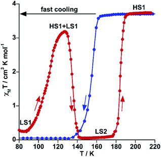 | ||
| Fig. 5 Thermal quenching of the HS state for 71As. Blue and red filled circles correspond to the cooling and heating modes, respectively. | ||
Structural analysis
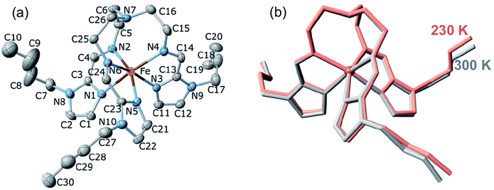
![[1 with combining macron]](https://www.rsc.org/images/entities/char_0031_0304.gif) , Table S1†). However, after many attempts, it was impossible to achieve a full structural analysis of the LS2 phase because single crystals shatter during the HS1 → LS2 transformation. The same reason prevented us from structurally characterising the plateau centred at 190 K in the heating branch of the LS2 → HS1 transition. The unit cell consists of two crystallographically identical complex cations of opposite chirality and four AsF6− counterions (two crystallographically distinct sites, denoted as As1 and As2) balancing the charge. The FeII ion is wrapped by three n-butyl-1H-imidazol-2-ylimino moieties, defining a pseudo-octahedral [FeN6] coordination environment (Fig. 6a), with Fe–N average bond lengths typical for the HS state and does not change substantially due to the PT: 2.199(4) Å and 2.190(7) Å at 230 K (HS1) and 300 K (HS2), respectively (Fig. 6b, Table S2†).
, Table S1†). However, after many attempts, it was impossible to achieve a full structural analysis of the LS2 phase because single crystals shatter during the HS1 → LS2 transformation. The same reason prevented us from structurally characterising the plateau centred at 190 K in the heating branch of the LS2 → HS1 transition. The unit cell consists of two crystallographically identical complex cations of opposite chirality and four AsF6− counterions (two crystallographically distinct sites, denoted as As1 and As2) balancing the charge. The FeII ion is wrapped by three n-butyl-1H-imidazol-2-ylimino moieties, defining a pseudo-octahedral [FeN6] coordination environment (Fig. 6a), with Fe–N average bond lengths typical for the HS state and does not change substantially due to the PT: 2.199(4) Å and 2.190(7) Å at 230 K (HS1) and 300 K (HS2), respectively (Fig. 6b, Table S2†).
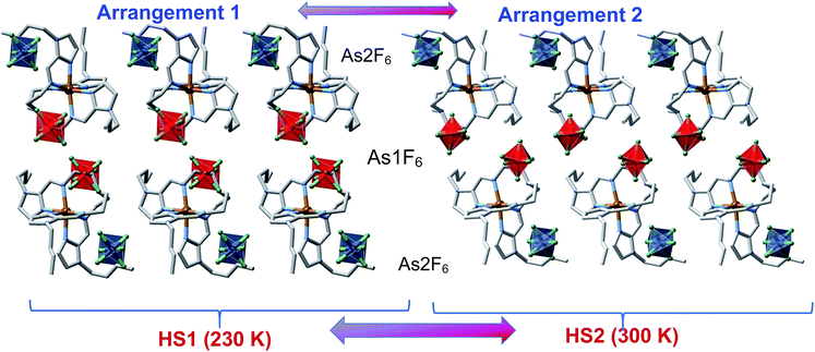
Upside-down arranged complex molecules are self-organized in bilayer assemblies extending in the ab plane whereas the AsF6− anions occupy both surfaces and the inner space of the bilayer (Fig. 7). At 230 K (HS1 phase), the inner space anions (As1F6−) are substantially shifted from the centre whereas the axes of anions are inclined with respect to the layer plane; the anions are ordered as well as butyl substituents of the complex cations, arrangement 1 in Fig. 7. On passing the temperature of the PT, the anisotropic change of the lattice decreases the lattice parameter c by 0.44 Å that is reflected by the shrinking of the interlayer distance from 22.01 Å at 230 K down to 21.85 Å at 300 K. Furthermore, the PT promotes arrangement 2 (HS2 phase), for which inner space anions As1F6− are located closer to the centre of the interspace between layers with their axes almost perpendicular to the layer plane (Fig. 7). Substantial disorder of the anions and butyl groups suggests that increasing entropy of the system is the driving force of the PT. Clearly, the transition is not related to the SCO as the coordination sphere of the FeII remains practically intact, although the rearranged anions and butyl groups change the pattern of intermolecular contacts CH⋯F in the lattice. For example, in the HS1 phase one discrete interaction C24⋯F2(As1) = 3.087(4) Å is below the van der Waals radii (3.17 Å),15 in contrast to the HS2 phase where no viable C⋯F contacts are operative. Furthermore, the percentage of weak intermolecular contacts C⋯F, N⋯H and C⋯H substantially changes due to the PT too, see Table S4.† This lattice dynamics in close proximity to the metal centre seems to noticeably affect the ligand field strength/g-factor and produce detectable magnetic bistability.16
It is worth recalling that similar structural rearrangement was observed for 100P. For cooling rates higher than 0.5 K min−1, 100P displays arrangement 1 in the LS state (LS1 phase) through channel A, while above TPTc ≈ 127 K it adopts arrangement 2 (LS2 phase) from channel B. Finally, on further heating it recovers arrangement 1 once the system reaches the HS state (HS1 phase) just above T↑c = 176 K (Fig. 3). It deserves to be noted the increase of disorder in the alkyl chains when both compounds adopt arrangement 2, see comparison of the colour mapped complex cation in pairs LS1–LS2 and HS1–HS2 in Fig. S7,† which is supposed to be the driving force of the observed PTs.
On cooling 100As, a second transition occurs as deduced from the magnetic data (Fig. 1a), however, the crystal rapidly and irreversibly deteriorates due to the SCO and therefore it was impossible to collect crystallographic data of the LS2 phase at 120 K or of the intermediate plateau at 190 K.
![[thin space (1/6-em)]](https://www.rsc.org/images/entities/char_2009.gif) :
:![[thin space (1/6-em)]](https://www.rsc.org/images/entities/char_2009.gif) (100 − x)PF6− solid solutions. It was expected to obtain direct information not only about the type of arrangement adopted by the LS state in this solid solution, which could be extrapolated to 100As, but also to obtain structural information about the HS state, in particular that of the metastable quenched HS1q at 120 K (see Fig. 5). Indeed, robust single crystals of 71AsF6−
(100 − x)PF6− solid solutions. It was expected to obtain direct information not only about the type of arrangement adopted by the LS state in this solid solution, which could be extrapolated to 100As, but also to obtain structural information about the HS state, in particular that of the metastable quenched HS1q at 120 K (see Fig. 5). Indeed, robust single crystals of 71AsF6−![[thin space (1/6-em)]](https://www.rsc.org/images/entities/char_2009.gif) :
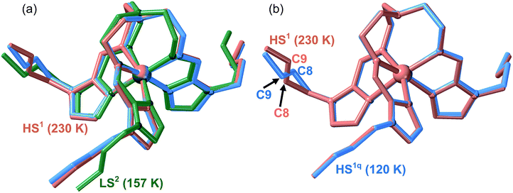
:![[thin space (1/6-em)]](https://www.rsc.org/images/entities/char_2009.gif) 29PF6− (71As) appropriate for single crystal X-ray analysis were prepared. A single crystal of 71As was firstly measured at 230 K (see Tables S1 and S2†) where the structure presents, as expected, arrangement 1 and the FeII centres are in the HS state (average Fe–N distance = 2.196 Å). The whole cation complex is virtually identical to that of 100As including the conformation of the butyl groups. Afterwards, the same crystal was slowly cooled from 230 K to 120 K to avoid any thermal quenching, and then the temperature was increased up to 157 K to place the system in the middle of the LS branch of the hysteresis and measured at this temperature (see Fig. 5). The corresponding structure exhibits arrangement 2 for the counterions with the butyl groups showing strong configurational differences with respect to the structure at 230 K (Fig. 8a). According to the magnetic properties, the Fe–N average distance, 1.964 Å, shows the occurrence of a complete HS1 → LS2 phase transformation (Table S2†).
29PF6− (71As) appropriate for single crystal X-ray analysis were prepared. A single crystal of 71As was firstly measured at 230 K (see Tables S1 and S2†) where the structure presents, as expected, arrangement 1 and the FeII centres are in the HS state (average Fe–N distance = 2.196 Å). The whole cation complex is virtually identical to that of 100As including the conformation of the butyl groups. Afterwards, the same crystal was slowly cooled from 230 K to 120 K to avoid any thermal quenching, and then the temperature was increased up to 157 K to place the system in the middle of the LS branch of the hysteresis and measured at this temperature (see Fig. 5). The corresponding structure exhibits arrangement 2 for the counterions with the butyl groups showing strong configurational differences with respect to the structure at 230 K (Fig. 8a). According to the magnetic properties, the Fe–N average distance, 1.964 Å, shows the occurrence of a complete HS1 → LS2 phase transformation (Table S2†).
Another single crystal of 71As was cooled directly from 300 K to 120 K and the structure of the HS1q phase was analysed (see Tables S1 and S2†). Despite the crystals being rather robust, we observed their deterioration during the measurement process due to relaxation from the quenched HS1q to the LS2 phase at 120 K. Consequently, in order to get reasonably good crystal data, initial partial data collection for the resolution of the structure was recorded. Indeed, this relaxation was slow enough to allow the acquisition of the required data (stable for ca. 45 min) to determine the structure before the collapse of the crystal. The analysis of the structure is consistent with the magnetic data and, based on the Fe–N average bond length, only ca. 5% of the FeII centres have relaxed to the LS2 state. The metastable quenched HS1q retains arrangement 1 of the parent HS1 phase and the [Fe(nBu-im)3(tren)]2+ cation is essentially the same except for the butyl [Im–C7–C8–C9–C10] which adopts a divergent configuration (see Fig. 8b).
The crystal structure of 100Ni, solved at 110 K, closely resembles that of 100P in LS1 phase,11bi.e. shows arrangement 1 (Fig. S8, Tables S1 and S3†).
Concluding remarks
The underlying reason for the observed rich magnetic behaviour of the systems 100P and 100As lies in their ability to exhibit ordered arrangement 1 and less ordered arrangement 2 in addition to the SCO transition between the HS and LS spin states. Both systems exhibit SCO behaviour synchronized with a structural PT featuring very slow kinetics compared with that of the SCO. Playing with this kinetics, the bistability domains of both transitions can overlap in temperature or can occur separately so that 100P and 100As can potentially form phases LS1, HS1 and LS2, HS2 and display transitions between them. Indeed, for 100P the phase bistability is operative in a temperature region overlapping with the SCO bistability giving the transition HS1 → LS2. Additionally, a narrow temperature window exists where the transition HS1 → LS1 occurs without change of the lattice arrangement. Moreover, the transition LS1 → LS2 is operative without change of the spin state but with a change of the lattice arrangement. The experimental data show the possibility of such transitions also for 100As and, additionally, at higher temperature another structural rearrangement HS1 → HS2 occurs within the HS state.Thus, both systems can exhibit “ordered” LS1 and HS1 phases and “disordered” LS2 and HS2 phases. For 100As we observe all four phases, for 100P all except the HS2, which is shifted so much in temperature that it does not occur below the melting temperature of 100P. The transition to the arrangement 2 phase occurs because the disordered n-butyl chains increase the entropy and decrease the Gibbs free energy of the system. The more prone tendency of 100As to disorder can be associated with the small volume expansion of the lattice induced by the PF6− → AsF6− substitution and evidenced by the much faster kinetics featuring the LS2 ↔ HS1 transition. The slightly larger AsF6− anions separate the SCO complex cations, thereby facilitating their n-butyl groups to become disordered and favoring the phases LS2 and HS2. This is corroborated by the transition HS1 ↔ HS2 (not coupled with the SCO) and by the fact that this transition is not observed for 100P.
The shift of the SCO and phase bistabilities of the PT on passing from 100P to 100As might be rationalized considering the “chemical pressure” (CP) of the anions as a qualitative measure of average intermolecular interactions and electrostatic pressure in the lattices. Indeed, external pressure applied to 100P progressively shifts the HS1 ↔ LS2 transition toward higher temperature and, more importantly, changes the hysteresis loop, which becomes two-step similarly to 100As. It is worth mentioning that the positive CP generated by application of “external” hydrostatic pressure increases the intermolecular contacts and stabilises the LS state by reducing the unit cell volume. In contrast, similar positive “internal” CP is generated upon PF6− → AsF6− substitution, which involves an increase of the unit cell volume in 42.44 Å3. To explain this apparent paradox we compared the crystal structures of 100P and 100As at the same temperature (230 K) making use of the Hirshfeld surface analysis.17 This analysis shows that the percentage of C⋯F contacts doubles when replacing PF6− with AsF6− (more moderate increase of contacts is also observed for F⋯H and C⋯H) (Fig. S9, Table S4†). This can be rationalised from the estimated void space, 46.54 and 43.83 Å3, available for 100P and 100As, respectively.17 Interestingly, the smaller empty space found for 100As shows that void space does not increase in parallel with the unit cell volume increase. This is the reason why the number of F⋯C contacts is larger for 100As, a fact in line with the observed increase of CP in 100As.
The similar chemical nature of both compounds makes them well suited for the study of the isomorphous series with varying ratio between the both. At a fixed scan rate of 2 K min−1 the kinetics of transitions HS1 → LS1 and HS1 → LS2 (memory channels A and B, respectively) is dramatically affected by changing the PF6−![[thin space (1/6-em)]](https://www.rsc.org/images/entities/char_2009.gif) :
:![[thin space (1/6-em)]](https://www.rsc.org/images/entities/char_2009.gif) AsF6− ratio. This is reflected in the changing contribution of the two channels to the shape of the observed hysteresis loops. Progressively increasing the amount of AsF6− favours the SCO with structural rearrangement and makes the observation of the process HS1 → LS1 impossible on passing a threshold concentration. Thus, for 71As the coalescence of the two hysteretic spin transitions vanishes affording a rectangular well-shaped hysteresis loop, which corresponds to the transition HS1 → LS2 where the structural rearrangement is realized.
AsF6− ratio. This is reflected in the changing contribution of the two channels to the shape of the observed hysteresis loops. Progressively increasing the amount of AsF6− favours the SCO with structural rearrangement and makes the observation of the process HS1 → LS1 impossible on passing a threshold concentration. Thus, for 71As the coalescence of the two hysteretic spin transitions vanishes affording a rectangular well-shaped hysteresis loop, which corresponds to the transition HS1 → LS2 where the structural rearrangement is realized.
Opposite to the [Fe(nBu-im)3(tren)](P1−yAsyF6)2 substituted systems, where included AsF6− anions create “positive” internal pressure and shift SCO upward in temperature, metal substitution in [Fe1−xMx(nBu-im)3(tren)](PF6)2 (21Zn or 17Ni) can be considered as creating “negative” internal pressure, stabilizing low temperature SCO. Indeed, as follows from the experimental data, dilution with ZnII or NiII ions, both more voluminous than the LS FeII ion, predictably favours the SCO transition to the more voluminous LS1 phase and disfavours compact LS2 (cell volume 1994.7(5) and 1950.8(15) Å3, respectively)11b and makes the low temperature transition LS1 ↔ HS1 the only option for the system. Thus, metal dilution with the NiII or ZnII stabilizes the voluminous arrangement 1 in both spin states and effectively suppresses the transition to arrangement 2.
In summary, we have reported an isomorphically substituted series of unusual FeII SCO complexes displaying two memory channels. We found that metal substitution with NiII or ZnII selectively favours arrangement 1 in both spin states, thus promoting a low temperature hysteretic SCO transition (channel A). On the other hand, substitution of its PF6− anion with AsF6− promotes a high temperature hysteretic SCO transition (channel B) as a result of favoured transformation to disordered arrangement 2 in the LS state, and thus the high temperature hysteretic transition is preferred.
For the first time, we demonstrate that decoupling of two synchronous cooperative events such as SCO and intrinsic structural phase transitions can be chemically achieved by choosing the appropriate isomorphous substitution (metal ion or anion in the present case) to selectively discriminate between two separate hysteretic SCO behaviours. The design of fully controllable smart materials able to respond to external stimuli in a desired way is a challenging target in materials science. The results here reported support the idea that bistable molecular materials exhibiting synergetic interplay between two or more phase transitions in the same crystal are particularly well suited to this end.
Experimental
Materials
[Fe(nBu-im)3tren](AsF6)2 (100As). A filtered solution of FeCl2·4H2O (0.043 g, 0.21 mmol) in absolute ethanol (5 mL) was added dropwise to a boiling solution of 1-butyl-1H-imidazole-2-carbaldehyde (0.10 g, 0.65 mmol), tris(2-ethanolamine)amin (tren) (0.031 g, 0.21 mmol) and [TBA]AsF6 (0.17 g, 0.43 mmol) in 5 mL of absolute ethanol. The resulting dark red-purple solution was stirred for 5 min. After keeping the solution for several days at 25 °C in a thermostat bath, well-shaped red-brown crystals of the product were formed and isolated. Calcd for C30H48As2F12FeN10: C, 36.68; H, 5.01; N, 14.10. Found: C, 36.39; H, 5.35; N, 14.25.
Similarly, the solid solutions [Fe1−xMx(nBu-im)3(tren)](PF6)2 (M = ZnII, NiII) were confirmed via EDXS analysis: 17Ni (83% Fe, 17% Ni), 21Zn (79% Fe, 21% Zn).
Physical characterization
Conflicts of interest
There are no conflicts to declare.Acknowledgements
This work was supported by the Spanish Ministerio de Economia y Competitividad (MINECO), FEDER (CTQ2016-78341-P), Unidad de Excelencia María de Maeztu (MDM-2015-0538), and the Generalitat Valenciana through PROMETEO/2016/147 and an EU Framework Program for Research and Innovation (RISE project number 734322). F. J. V. M. and M. M. S. thank MINECO for a predoctoral (FPI) grant.Notes and references
- (a) K. H. Bennemann, J. Phys.: Condens. Matter, 2011, 23, 073202 CrossRef CAS PubMed; (b) O. Sato, Nat. Chem., 2016, 8, 644–656 CrossRef CAS PubMed; (c) S.-y. Koshihara, J. Phys.: Conf. Ser., 2005, 21, 7–14 CrossRef CAS.
- (a) E. König, Struct. Bonding, 1991, 76, 51–152 CrossRef; (b) P. Gütlich, A. Hauser and H. Spiering, Angew. Chem., Int. Ed. Engl., 1994, 33, 2024–2054 CrossRef; (c) J. A. Real, A. B. Gaspar, V. Niel and M. C. Muñoz, Coord. Chem. Rev., 2003, 236, 121–141 CrossRef CAS; (d) Spin Crossover in Transition Metal Compounds, ed. P. Gütlich and H. Goodwin, Top. Curr. Chem., 2004, vol. 233–235 Search PubMed; (e) J. A. Real, A. B. Gaspar and M. C. Muñoz, Dalton Trans., 2005, 2062–2079 RSC; (f) M. A. Halcrow, Polyhedron, 2007, 26, 3523–3576 CrossRef CAS; (g) A. Bousseksou, G. Molnár, L. Salmon and W. Nicolazzi, Chem. Soc. Rev., 2011, 40, 3313–3335 RSC.
- (a) O. Kahn and J. Martinez, Science, 1998, 279, 44–48 CrossRef CAS; (b) M. Ohba, K. Yoneda, G. Agusí, M. C. Munoz, A. B. Gaspar, J. A. Real, M. Yamasaki, H. Ando, Y. Nakao, S. Sakaki and S. Kitagawa, Angew. Chem., Int. Ed., 2009, 48, 4767–4771 CrossRef CAS PubMed; (c) L. Salmon, G. Molnar, D. Zitouni, C. Quintero, C. Bergaud, J.-C. Micheau and A. Bousseksou, J. Mater. Chem., 2010, 20, 5499–5503 RSC; (d) F. Prins, M. Monrabal-Capilla, E. A. Osorio, E. Coronado and H. S. J. van der Zant, Adv. Mater., 2011, 23, 1545–1549 CrossRef CAS PubMed; (e) M. Matsuda, K. Kiyoshima, R. Uchida, N. Kinoshita and H. Tajima, Thin Solid Films, 2013, 531, 451–453 CrossRef CAS; (f) H. J. Shepherd, I. y. A. Gural'skiy, C. M. Quintero, S. Tricard, L. Salmon, G. Molnár and A. Bousseksou, Nat. Commun., 2013, 4(1–9), 2607 CrossRef PubMed.
- (a) H. Matsukizono, K. Kuroiwa and N. Kimizuka, Chem. Lett., 2008, 37, 446–447 CrossRef CAS; (b) C. Lochenie, K. Schotz, F. Panzer, H. Kurz, B. Maier, F. Puchtler, S. Agarwal, A. Kohler and B. Weber, J. Am. Chem. Soc., 2018, 140, 700–709 CrossRef CAS PubMed; (c) T. Delgado, M. Meneses-Sánchez, L. Piñeiro-López, C. Bartual-Murgui, M. C. Muñoz and J. A. Real, Chem. Sci., 2018, 9, 8446–8452 RSC.
- (a) Y.-C. Chen, Y. Meng, Z.-P. Ni and M.-L. Tong, J. Mater. Chem. C, 2015, 3, 945–949 RSC; (b) Y.-S. Koo and J. R. Galán-Mascarós, Adv. Mater., 2014, 26, 6785–6789 CrossRef CAS PubMed.
- S. Bonhommeau, P. G. Lacroix, D. Talaga, A. Bousseksou, M. Seredyuk, I. O. Fritsky and V. Rodriguez, J. Phys. Chem. C, 2012, 116, 11251–11255 CrossRef CAS.
- (a) G. Molnar, S. Rat, L. Salmon, W. Nicolazzi and A. Bousseksou, Adv. Mater., 2018, 30(1–23), 17003862 Search PubMed; (b) K. Senthil Kumar and M. Ruben, Coord. Chem. Rev., 2017, 346, 176–205 CrossRef CAS.
- (a) T. Tayagaki, A. Galet, G. Molnar, M. C. Muñoz, A. Zwick, K. Tanaka, J. A. Real and A. Bousseksou, J. Phys. Chem. B, 2005, 109, 14859–14867 CrossRef CAS PubMed; (b) C. Balde, C. Desplanches, P. Gutlich, E. Freysz and J. F. Letard, Inorg. Chim. Acta, 2008, 361, 3529–3533 CrossRef CAS; (c) Z. Yu, T. Kuroda-Sowa, H. Kume, T. Okubo, M. Maekawa and M. Munakata, Bull. Chem. Soc. Jpn., 2009, 82, 333–337 CrossRef CAS; (d) P. Chakraborty, C. Enachescu, A. Humair, L. Egger, T. Delgado, A. Tissot, L. Guenee, C. Besnard, R. Bronisz and A. Hauser, Dalton Trans., 2014, 43, 17786–17796 RSC; (e) C. Baldé, C. Desplanches, J. F. Létard and G. Chastanet, Polyhedron, 2017, 123, 138–144 CrossRef.
- (a) C. A. Tovee, C. A. Kilner, J. A. Thomas and M. A. Halcrow, CrystEngComm, 2009, 11, 2069–2077 RSC; (b) M. A. Halcrow, Chem. Commun., 2010, 46, 4761–4763 RSC.
- (a) D. Braga, G. Cojazzi, D. Paolucci and F. Grepioni, Chem. Commun., 2001, 803–804 RSC; (b) M. Zhao, H. Peng, J. Hu and Z. Han, Sens. Actuators, B, 2008, 129, 953–957 CrossRef CAS; (c) R. Zhang, H. Jifan, H. Zhouxiang, Z. Ma, W. Zhanlei, Y. Zhang and Q. Hongwei, J. Rare Earths, 2010, 28, 591–595 CrossRef CAS; (d) D. M. Pajerowski, T. Yamamoto and Y. Einaga, Inorg. Chem., 2012, 51, 3648–3655 CrossRef CAS PubMed; (e) Y. Sun, Z. Zhu, J. Li, S. Gao, H. Xia, Z. You, Y. Wang and C. Tu, Opt. Mater., 2015, 49, 85–89 CrossRef CAS; (f) S. Chorazy, J. J. Stanek, W. Nogaś, A. M. Majcher, M. Rams, M. Kozieł, E. Juszyńska-Gałązka, K. Nakabayashi, S.-i. Ohkoshi, B. Sieklucka and R. Podgajny, J. Am. Chem. Soc., 2016, 138, 1635–1646 CrossRef CAS PubMed.
- (a) M. Seredyuk, A. B. Gaspar, V. Ksenofontov, Y. Galyametdinov, J. Kusz and P. Gütlich, J. Am. Chem. Soc., 2008, 130, 1431–1439 CrossRef CAS PubMed; (b) M. Seredyuk, M. C. Muñoz, M. Castro, T. Romero-Morcillo, A. B. Gaspar and J. A. Real, Chem.–Eur. J., 2013, 19, 6591–6596 CrossRef CAS PubMed; (c) M. Seredyuk, M. C. Muñoz, V. Ksenofontov, P. Gütlich, Y. Galyametdinov and J. A. Real, Inorg. Chem., 2014, 53, 8442–8454 CrossRef CAS PubMed; (d) T. Romero-Morcillo, M. Seredyuk, M. C. Muñoz and J. A. Real, Angew. Chem., Int. Ed., 2015, 54, 14777–14781 CrossRef CAS PubMed; (e) M. Seredyuk, K. Znovjyak, M. C. Munoz, Y. Galyametdinov, I. O. Fritsky and J. A. Real, RSC Adv., 2016, 6, 39627–39635 RSC; (f) T. Delgado, A. Tissot, L. Guénée, A. Hauser, F. J. Valverde-Muñoz, M. Seredyuk, J. A. Real, S. Pillet, E.-E. Bendeif and C. Besnard, J. Am. Chem. Soc., 2018, 140, 12870–12876 CrossRef CAS PubMed.
- (a) J. Jeftić, H. Romstedt and A. Hauser, J. Phys. Chem. Solids, 1996, 57, 1743–1750 CrossRef; (b) S. Hayami, Y. Komatsu, T. Shimizu, H. Kamihata and Y. H. Lee, Coord. Chem. Rev., 2011, 255, 1981–1990 CrossRef CAS; (c) S. Schlamp, B. Weber, A. D. Naik and Y. Garcia, Chem. Commun., 2011, 47, 7152–7154 RSC; (d) M. Yamasaki and T. Ishida, J. Mater. Chem. C, 2015, 3, 7784–7787 RSC; (e) A. B. Gaspar and M. Seredyuk, Coord. Chem. Rev., 2014, 268, 41–58 CrossRef CAS; (f) D. Rosario-Amorin, P. Dechambenoit, A. Bentaleb, M. Rouzières, C. Mathonière and R. Clérac, J. Am. Chem. Soc., 2018, 140, 98–101 CrossRef CAS PubMed; (g) T. Fujinami, K. Nishi, D. Hamada, K. Murakami, N. Matsumoto, S. Iijima, M. Kojima and Y. Sunatsuki, Inorg. Chem., 2015, 54, 7291–7300 CrossRef CAS PubMed; (h) T. Ueno, Y. Ii, T. Fujinami, N. Matsumoto, S. Iijima and Y. Sunatsuki, Polyhedron, 2017, 136, 13–22 CrossRef CAS; (i) M. Weselski, M. Książek, D. Rokosz, A. Dreczko, J. Kusz and R. Bronisz, Chem. Commun., 2018, 54, 3895–3898 RSC.
- J. F. Létard, P. Guionneau, O. Nguyen, J. S. Costa, S. Marcen, G. Chastanet, M. Marchivie and L. Goux-Capes, Chem.–Eur. J., 2005, 11, 4582–4589 CrossRef PubMed.
- V. Ksenofontov, A. B. Gaspar and P. Gütlich, Top. Curr. Chem., 2004, 235, 23–64 CrossRef CAS.
- A. Bondi, J. Phys. Chem., 1964, 68, 441–451 CrossRef CAS.
- G. Juhász, R. Matsuda, S. Kanegawa, K. Inoue, O. Sato and K. Yoshizawa, J. Am. Chem. Soc., 2009, 131, 4560–4561 CrossRef PubMed.
- (a) M. J. Turner, J. J. Mckinnon, S. K. Wolff, D. J. Grimwood, P. R. Spackman, D. Jayatilaka and M. A. Spackman, CrystalExplorer 17.5, The University of Western Australia, 2018 Search PubMed; (b) M. J. Turner, J. J. Mckinnon, D. Jayatilaka and P. R. Spackman, CrystEngComm, 2011, 13, 1804–1813 RSC.
- M. Baran, V. P. Dyakonov, L. Gladczuk, G. G. Levchenko, S. Piechota and G. Szymczak, Phys. C, 1995, 241, 383–388 CrossRef CAS.
- A. Eiling and J. S. Schilling, J. Phys. F: Met. Phys., 1981, 11, 623–639 CrossRef CAS.
- G. M. Sheldrick, Acta Crystallogr., Sect. C: Struct. Chem., 2015, 71, 3–8 Search PubMed.
Footnote |
| † Electronic supplementary information (ESI) available. CCDC 1879896–1879901 and 1892385. For ESI and crystallographic data in CIF or other electronic format see DOI: 10.1039/c8sc05256e |
| This journal is © The Royal Society of Chemistry 2019 |

