 Open Access Article
Formation of trigons in a metal–organic framework: The role of metal–organic polyhedron subunits as meta-atoms†
Jiyoung
Lee
a,
Jae Sun
Choi
b,
Nak Cheon
Jeong
 b and
Wonyoung
Choe
 *a
*a
aDepartment of Chemistry, Ulsan National Institute of Science and Technology, Ulsan 44919, Korea. E-mail: choe@unist.ac.kr
bDepartment of Emerging Materials Science, Daegu Gyeongbuk Institute of Science and Technology, Daegu 42988, Korea
First published on 14th May 2019
Abstract
Shape control of metal–organic materials on the meso- and macroscale has been an important theme due to emerging properties. Particularly, chemical etching has been useful to create various forms such as core–shells and hollow crystals in metal–organic frameworks. Here we present a unique chemical etching strategy to create trigonal patterned surfaces in metal–organic frameworks. The mechanism suggests that metal–organic polyhedron subunits serve as meta-atoms, playing a crucial role in the formation of trigons on the surface. Such a patterned surface in porous solids can be utilized in meta-surface applications in the foreseeable future.
Introduction
Metal–organic frameworks (MOFs) assembled from metal nodes and organic linkers are highly tunable materials,1–3 and now more than 70![[thin space (1/6-em)]](https://www.rsc.org/images/entities/char_2009.gif) 000 structures are available with several hundred well-established topologies.4 Precise shape control of MOFs on the meso- and macroscale is becoming a new synthetic challenge because such controlled MOFs open up new opportunities in emerging applications,5–7 in addition to conventional ones such as gas storage and catalysis.8,9 Among the several synthetic strategies, such as the templating-assisted method,10,11 defect-engineering method,12 perturbation-assisted nanofusion method13,14 and polymer coating method,15 chemical etching is a simple and straightforward method for synthesizing shape-controlled MOFs, using various etchants such as cyanuric chloride, sodium chloride, hydroquinone, and water.16–19 The results of chemical etching are often random shapes, which are evidence of uncontrolled reactions. This clearly indicates the need for a precisely controlled synthetic strategy. A noteworthy example is the work from the Maspoch group, demonstrating unprecedented morphologies of ZIF-8 and ZIF-67 via anisotropic chemical etching.20 Kim group synthesized a hierarchical structure having random etching patterns via a size-selective acid etching strategy.21 However, shape control still remains a daunting challenge to form regular surface patterns unlike the cases in silicon-based materials.22,23
000 structures are available with several hundred well-established topologies.4 Precise shape control of MOFs on the meso- and macroscale is becoming a new synthetic challenge because such controlled MOFs open up new opportunities in emerging applications,5–7 in addition to conventional ones such as gas storage and catalysis.8,9 Among the several synthetic strategies, such as the templating-assisted method,10,11 defect-engineering method,12 perturbation-assisted nanofusion method13,14 and polymer coating method,15 chemical etching is a simple and straightforward method for synthesizing shape-controlled MOFs, using various etchants such as cyanuric chloride, sodium chloride, hydroquinone, and water.16–19 The results of chemical etching are often random shapes, which are evidence of uncontrolled reactions. This clearly indicates the need for a precisely controlled synthetic strategy. A noteworthy example is the work from the Maspoch group, demonstrating unprecedented morphologies of ZIF-8 and ZIF-67 via anisotropic chemical etching.20 Kim group synthesized a hierarchical structure having random etching patterns via a size-selective acid etching strategy.21 However, shape control still remains a daunting challenge to form regular surface patterns unlike the cases in silicon-based materials.22,23
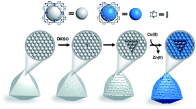
While we have studied chemical etching methods to synthesize a MOF built from cuboctahedron metal–organic polyhedra (MOPs), to our surprise, we have found a new strategy to pattern the surface of MOFs with a trigonal shape. The etching strategy is performed by using chemical etching using dimethyl sulfoxide (DMSO) and subsequent transmetalation (Fig. 1). Through this novel synthetic strategy, we successfully obtained MOFs with trigonal surface patterns. Furthermore, these resulting trigons, a well-known phenomenon from atomic to macroscopic levels in carbon-based and boron–nitrogen compounds,24–28 suggest that MOPs serve as meta-atoms.
Results and discussion
Zn-UMOM-10 (UMOM: UNIST metal–organic material) was selected as a starting material for this study. Zn-UMOM-10 was obtained by a solvothermal reaction of Zn(NO3)2·6H2O, 2,7-naphthalenedicarboxylate (2,7-NDC) and 1,4-diazabicyclo[2.2.2]octane (dabco) in N,N-dimethylformamide (DMF) by modifying a previous synthetic method.29 A colorless crystal of Zn-UMOM-10 was obtained and the X-ray powder diffraction pattern of the as-synthesized Zn-UMOM-10 shows that it has the same structure known as ZND reported by Chun et al. (Fig. S1†).29 Zn-UMOM-10 has a ubt topology, composed of a Zn2(COO)4 paddle-wheel as the metal node, and 2,7-NDC and dabco as organic linkers.Due to the instability of Zn(II) paddle-wheel MOFs upon axial solvent removal30–33 and labile Zn–O coordination bonding,34 we hypothesized that Zn-UMOM-10 could be suitable for the chemical etching reaction. To test such a hypothesis, we synthesized another MOF via a transmetalation reaction with a copper source. When the as-synthesized crystals of Zn-UMOM-10 were soaked in 0.1 M Cu(NO3)2 solution for 24 hours, blue crystals were collected (Fig. 2a) and their phase purity was confirmed using the X-ray powder diffraction pattern, and subsequently by X-ray single crystal analysis (Fig. 2b, c and Table S1†). The single crystal structure of this phase confirms that this compound has the same structure as Zn-UMOM-10, except for slight changes in the paddle-wheel node. We find that the two metals coordinated to dabco and solvent are different, resulting in a hetero-bimetallic paddle-wheel system, i.e. Zn(II) coordinated to dabco and Cu(II) to solvent molecules. Doonan’s group has reported hetero-bimetallic Pd(II)–M(II) (M = Cu, Ni, and Zn) paddle-wheel systems based on endo-site preferential localization of Pd(II) because of their square planar geometry.35 Maspoch et al. showed the formation of hetero-bimetallic Cu(II)–Zn(II) and Cu(II)–Ni(II) paddle-wheel clusters via water-induced single-crystal-to-single-crystal transformation.36 We compared the metal–metal distances of the paddle-wheels, dMM, of this and other MOP-based MOFs (Fig. 2d and Table S2†). Compared to Zn(II)–Zn(II) (2.93 Å)29 and Cu(II)–Cu(II) (2.67 Å)37 paddle-wheel distances found in ZND and UMOM-2, respectively, the dMM found here, 2.74 Å, is between these two values. On the other hand, the distance between metal–nitrogen, dMN, is similar to the dMN found in ZND. In addition, the angle of C–O–Zn, θ1 (128.34°), of this phase is similar to the angle in ZND (128.08°) and the angle of C–O–Cu, θ2 (123.53°), has a similar value to that of UMOM-2 (123.63°). Inductively coupled plasma analysis data show that there is a plateau at about 50% of the transmetalation reaction even if the reaction time is significantly increased, indicating that the amount of copper and zinc is around 50![[thin space (1/6-em)]](https://www.rsc.org/images/entities/char_2009.gif) :
:![[thin space (1/6-em)]](https://www.rsc.org/images/entities/char_2009.gif) 50 (Fig. S2†). Elemental mapping of a single crystal shows a uniform distribution of Cu and Zn (Fig. S3†). Raman spectra also support the hetero-bimetallic paddle-wheel feature. When we exchanged the solvent molecule coordinated to the metal inside the cuboctahedron cage, there is a peak shift only in the v(Cu–O) region and not in the v(Zn–O) region (Fig. S4†). We speculated that dabco molecules act as a protective group to hamper metal exchange during the transmetalation reaction. Based on these data, we concluded that this phase is indeed ordered hetero-bimetallic Zn/Cu-UMOM-10 with a ubt topology, consisting of face-centered cubic (fcc) packed cuboctahedron cages, assembled from the ZnCu(COO)4 paddle-wheel and 2,7-NDC. Similar formation of bimetallic metal nodes was reported by Sun et al.38 They noticed that Zn(II) coordinated with a dabco molecule was not exchanged to Cu(II). However, Zn(II) coordinated to a solvent molecule was exchanged to Cu(II).38 In Zn/Cu-UMOM-10, each cuboctahedron cage is surrounded by twelve neighboring identical cages and inter-connected by dabco linkers.
50 (Fig. S2†). Elemental mapping of a single crystal shows a uniform distribution of Cu and Zn (Fig. S3†). Raman spectra also support the hetero-bimetallic paddle-wheel feature. When we exchanged the solvent molecule coordinated to the metal inside the cuboctahedron cage, there is a peak shift only in the v(Cu–O) region and not in the v(Zn–O) region (Fig. S4†). We speculated that dabco molecules act as a protective group to hamper metal exchange during the transmetalation reaction. Based on these data, we concluded that this phase is indeed ordered hetero-bimetallic Zn/Cu-UMOM-10 with a ubt topology, consisting of face-centered cubic (fcc) packed cuboctahedron cages, assembled from the ZnCu(COO)4 paddle-wheel and 2,7-NDC. Similar formation of bimetallic metal nodes was reported by Sun et al.38 They noticed that Zn(II) coordinated with a dabco molecule was not exchanged to Cu(II). However, Zn(II) coordinated to a solvent molecule was exchanged to Cu(II).38 In Zn/Cu-UMOM-10, each cuboctahedron cage is surrounded by twelve neighboring identical cages and inter-connected by dabco linkers.
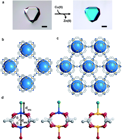 | ||
| Fig. 2 (a) Optical microscopy images of Zn-UMOM-10 (left) and Zn/Cu-UMOM-10 (right) after the transmetalation reaction. Scale bar, 100 μm. Perspective view of the (b) (100) plane and (c) (111) plane of Zn/Cu-UMOM-10. Zn, blue; Cu, yellow; C, grey; O, grey; N, grey; all hydrogen atoms and solvent molecules on the paddle-wheel are omitted for clarity. (d) Zn(II)–Zn(II) paddle-wheel structures of ZND27 (left), Zn(II)–Cu(II) paddle-wheel structures of Zn/Cu-UMOM-10 (middle) and Cu(II)–Cu(II) paddle-wheel structures of UMOM-2 (ref. 35) (right). Zn, blue; Cu, yellow; C, grey; O, red; N, green. | ||
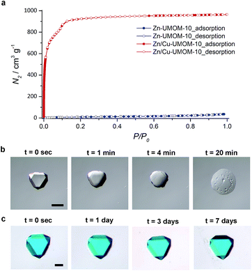
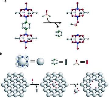
The difference in structural and chemical stability of Zn-UMOM-10 and Zn/Cu-UMOM-10 was tested by their gas sorption analysis and a solubility test in DMSO. To confirm the permanent porosity, N2 sorption isotherms of Zn-UMOM-10 and Zn/Cu-UMOM-10 were obtained after activation at 30 °C for 6 h. After activation, the color of Zn-UMOM-10 changed from colorless to yellow, indicating the structural decomposition.35 Also, we failed to obtain the N2 sorption isotherm even after several attempts. Unlike Zn-UMOM-10, the permanent porosity of Zn/Cu-UMOM-10 was confirmed by their N2 sorption isotherm and BET surface area of 3270 m2 g−1, similar to the calculated surface area of 3570 m2 g−1 by using the Zeo++ program39,40 with a 1.8 Å probe radius which is the same as the N2 radius (Fig. 3a). When we soaked single crystals of Zn-UMOM-10 and Zn/Cu-UMOM-10 in DMSO, the crystal of Zn-UMOM-10 dissolved within a few hours, but there was no change in the crystals of Zn/Cu-UMOM-10 (Fig. 3b). Indeed, the X-ray powder diffraction patterns show that the crystallinity was well-maintained when we soaked Zn/Cu-UMOM-10 in DMSO for 7 days (Fig. S5†). We speculate that these stability differences between Zn-UMOM-10 and Zn/Cu-UMOM-10 represent different binding energies of Zn–dabco in Zn(II) paddle-wheel and Zn(II)–Cu(II) hetero-bimetallic paddle-wheel cases similar to the binding energy difference between CO2 and metal centers in each case.41 A plausible mechanism for the dissolution of Zn-UMOM-10 is the following (Fig. 4). A dabco molecule coordinated to the Zn(II) paddle-wheel is replaced by a DMSO molecule because the distance between two paddle-wheels is too short for two DMSO molecules to coordinate. Such an event will create different paddle-wheel metal centers; one is an axial coordination site occupied with a DMSO molecule, and the other is unoccupied. After replacement, structural deformation occurs due to the changes of the coordination number of Zn2+ in the unoccupied axial site. The structural instability of the Zn(II) paddle-wheel in the absence of the axial solvent has been well-established by several previous studies.30–32
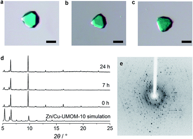
Based on such different stabilities, Zn/Cu-UMOM-10-ce (ce stands for chemical etching) was obtained after an etching reaction with dilute DMSO, followed by a transmetalation reaction of Cu(II). When we used pure DMSO during the etching reaction of Zn-UMOM-10, the reaction was too fast as we demonstrated. Therefore, dilute DMSO in DMF is used as an etchant instead of pure DMSO to slow down the etching reaction. Optical microscopy images show that there is no morphology change after reactions (Fig. 5a–c). Their crystallinity was maintained after 24 h of etching and transmetalation reactions, as shown in X-ray powder diffraction analysis (Fig. 5d). Surprisingly, their single crystallinity was maintained after 48 h of etching reaction as shown in Fig. 5e. Scanning electron microscopy (SEM) images reveal a peculiar pattern in the surface of Zn/Cu-UMOM-10-ce. Micro-sized trigonal patterns can be seen on the surface of crystals (Fig. 6a–d). After 7 h of etching reaction, a few micro-sized trigonal patterns appeared on the surface of the (111)-type face. Interestingly, when we increased the etching reaction time, the trigons aggregated, and the surface became rougher (Fig. S6†). The formation of these trigonal patterns can be rationalized by anisotropic etching, caused by different etching rates in the [111], [110], and [100] directions (Fig. 6e). These horizontal etching phenomena represent that there is a preferential etching reaction along the [110] and [100] directions compared to the etching reaction along the [111] direction. Because of the different numbers of exposed dabco per unit area of each plane, (111)![[thin space (1/6-em)]](https://www.rsc.org/images/entities/char_2009.gif) :
:![[thin space (1/6-em)]](https://www.rsc.org/images/entities/char_2009.gif) (100)
(100)![[thin space (1/6-em)]](https://www.rsc.org/images/entities/char_2009.gif) :
:![[thin space (1/6-em)]](https://www.rsc.org/images/entities/char_2009.gif) (110) = 3√3
(110) = 3√3![[thin space (1/6-em)]](https://www.rsc.org/images/entities/char_2009.gif) :
:![[thin space (1/6-em)]](https://www.rsc.org/images/entities/char_2009.gif) 2
2![[thin space (1/6-em)]](https://www.rsc.org/images/entities/char_2009.gif) :
:![[thin space (1/6-em)]](https://www.rsc.org/images/entities/char_2009.gif) 2, there are different etching rates in each plane. In other words, the etching reaction takes place quickly in the plane having a small number of dabco molecules. Such a phenomenon is quite similar to anisotropic etching on the (111) surface of silicon which shows that the etching rate is different depending on the number of dangling bonds in each plane.42 Furthermore, focused ion beam images show that these patterns exist only on the surface of crystals (Fig. S7†). Such a phenomenon is quite similar to the etching patterns in a platinum electrode which is composed of fcc packed platinum atoms (Fig. S8†).43 The triangular etched pits were formed when cathodic corrosion occurred on the (111)-type surface. A diamond and silicon also have similar trigonal patterns on their (111) face after thermal/chemical etching (Fig. 6f and g).23–27 Based on structural similarity between Zn/Cu-UMOM-10-ce and these known examples, we speculate that cuboctahedron MOP cages in Zn-UMOM-10 are acting as ‘meta-atoms’ such as platinum and carbon atoms in fcc Pt and diamond structures, respectively, during the etching reaction.
2, there are different etching rates in each plane. In other words, the etching reaction takes place quickly in the plane having a small number of dabco molecules. Such a phenomenon is quite similar to anisotropic etching on the (111) surface of silicon which shows that the etching rate is different depending on the number of dangling bonds in each plane.42 Furthermore, focused ion beam images show that these patterns exist only on the surface of crystals (Fig. S7†). Such a phenomenon is quite similar to the etching patterns in a platinum electrode which is composed of fcc packed platinum atoms (Fig. S8†).43 The triangular etched pits were formed when cathodic corrosion occurred on the (111)-type surface. A diamond and silicon also have similar trigonal patterns on their (111) face after thermal/chemical etching (Fig. 6f and g).23–27 Based on structural similarity between Zn/Cu-UMOM-10-ce and these known examples, we speculate that cuboctahedron MOP cages in Zn-UMOM-10 are acting as ‘meta-atoms’ such as platinum and carbon atoms in fcc Pt and diamond structures, respectively, during the etching reaction.
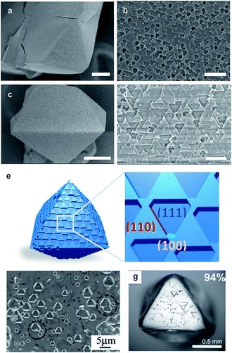 | ||
| Fig. 6 SEM images of Zn/Cu-UMOM-10-ce with an etching time of (a and b) 7 h and (c and d) 24 h. Scale bar (a and c) 50 μm, (b and d) 10 μm. (e) Illustration of the crystal morphology of Zn/Cu-UMOM-10-ce. Crystallographic planes of (111), (110) and (100) are represented in blue, red and green, respectively. Photographs of etching patterns on a (111) face of (f) silicon wafer.23 Copyright 2009 Rights Managed by the Royal Society of Chemistry. (g) A single crystal of diamond.25 Copyright 2007 Rights Managed by the Mineralogical Society of America. | ||
The permanent porosity and the micro/mesoporosity of Zn/Cu-UMOM-10-ce are confirmed by their N2 sorption isotherm at 77 K. The Zn/Cu-UMOM-10-ce has a BET surface area of 3310 m2 g−1 and there is no difference compared to that of Zn/Cu-UMOM-10 (Fig. S9a†). We confirmed that there are three different micropores of Zn/Cu-UMOM-10-ce, which were analyzed using a DFT model. These three different pores at 1.88, 2.17 and 2.30 nm are well-matched with the micropores of Zn/Cu-UMOM-10 except for a slightly reduced pore volume (Fig. S9b†). Interestingly, there is an increase in N2 uptake amount at high pressure due to the slight increase of mesoporous features of Zn/Cu-UMOM-10-ce on the surface of crystals during the etching reaction unlike the result for Zn/Cu-UMOM-10. After etching, macroporous features of Zn/Cu-UMOM-10-ce were observed. Pore size distribution data in the macropore range (50–5000 nm) obtained by mercury porosimetry show the macroporosity of Zn/Cu-UMOM-10-ce (Fig. S10b†) unlike for Zn/Cu-UMOM-10.
Conclusions
In summary, we demonstrated a new etching strategy to create a patterned MOF. The trigonal patterned MOF (Zn/Cu-UMOM-10-ce) was synthesized as the first example via chemical etching, followed by a transmetalation reaction. The formation of trigonal patterns on the (111)-type surface of Zn/Cu-UMOM-10-ce is similar to the well-known phenomenon in fcc Pt and diamond/silicon structures having a diamond atomic structure. Based on the structural similarity found in those materials, we suggest a plausible mechanism for the etching reaction, suggesting that cuboctahedron MOP cages act as sacrificial meta-atoms, just like Pt atoms. Furthermore, we demonstrated that the origin of the macroporous feature of Zn/Cu-UMOM-10-ce comes from these etching patterns. We expect that this novel chemical etching strategy, together with the concept, could be utilized as a significant tool for modifying the surface properties of materials (e.g. controlling hydrophobicity and surface functionalization via area selective atomic layer deposition),44,45 and further fabricating a meta-surface with a periodic or quasi-periodic two-dimensional planar arrangement of meta-atoms.46–49 A good example is the plasmonic meta-surface having a triangle hole-array of the metal nanostructure which produces countercircularly polarized second-harmonic generation beams although the material itself is achiral.49Conflicts of interest
There are no conflicts to declare.Acknowledgements
This work was supported by the National Research Foundation of Korea (NRF-2016R1A5A1009405, NRF-2015R1D1A1A0206173 8 and NRF-2014K1A3A1A09063072). The authors acknowledge Pohang Accelerator Laboratory (PAL) for 2D beamline use (2017-1st-2D-032) and would like to thank Professor Hyun Sung Kim at Pukyong National University for the macropore measurement.Notes and references
- H. Furukawa, K. E. Cordova, M. O'Keeffe and O. M. Yaghi, Science, 2013, 341, 123044 CrossRef PubMed.
- W. Lu, Z. Wei, Z.-Y. Gu, T.-F. Liu, J. Park, J. Park, J. Tian, M. Zhang, Q. Zhang, T. Gentle III, M. Bosch and H.-C. Zhou, Chem. Soc. Rev., 2014, 43, 5561–5593 RSC.
- H.-C. Zhou, J. R. Long and O. M. Yaghi, Chem. Rev., 2012, 112, 673–674 CrossRef CAS PubMed.
- P. Z. Moghadam, A. Li, S. B. Wiggin, A. Tao, A. G. P. Maloney, P. A. Wood, S. C. Ward and D. Fairen-Jimenez, Chem. Mater., 2017, 29, 2618–2625 CrossRef CAS.
- L.-G. Qiu, T. Xu, Z.-Q. Li, W. Wang, Y. Wu, X. Jiang, X.-Y. Tian and L.-D. Zhang, Angew. Chem., Int. Ed., 2008, 47, 9487–9491 CrossRef CAS PubMed.
- Y. Yue, P. F. Fulvio and S. Dai, Acc. Chem. Res., 2015, 48, 3044–3052 CrossRef CAS PubMed.
- Z. Fang, B. Bueken, D. E. De Vos and R. A. Fischer, Angew. Chem., Int. Ed., 2015, 54, 7234–7254 CrossRef CAS PubMed.
- C. Perego and R. Millini, Chem. Soc. Rev., 2013, 42, 3956–3976 RSC.
- M. E. Davis, Nature, 2002, 417, 813 CrossRef CAS PubMed.
- H. Huang, J.-R. Li, K. Wang, T. Han, M. Tong, L. Li, Y. Xie, Q. Yang, D. Liu and C. Zhong, Nat. Commun., 2015, 6, 8847 CrossRef CAS PubMed.
- W. Zhang, Y. Liu, G. Lu, Y. Wang, S. Li, C. Cui, J. Wu, Z. Xu, D. Tian, W. Huang, J. S. DuCheneu, W. D. Wei, H. Chen, Y. Yang and F. Huo, Adv. Mater., 2015, 27, 2923–2929 CrossRef CAS PubMed.
- K. M. Choi, H. J. Jeon, J. K. Kang and O. M. Yaghi, J. Am. Chem. Soc., 2011, 133, 11920–11923 CrossRef CAS PubMed.
- Y. Yue, Z.-A. Qiao, P. F. Fulvio, A. J. Binder, C. Tian, J. Chen, K. M. Nelson, X. Zhu and S. Dai, J. Am. Chem. Soc., 2013, 135, 9572–9575 CrossRef CAS PubMed.
- Y. Yue, A. J. Binder, R. Song, Y. Cui, J. Chen, D. K. Hensley and S. Dai, Dalton Trans., 2014, 43, 17893–17898 RSC.
- J. Yi, H. Li, L. Jiang, K. Zhang and D. Chen, Chem. Commun., 2015, 51, 10162–10165 RSC.
- Y. Yoo and H.-K. Jeong, Chem. Eng. J., 2012, 181, 740–745 CrossRef.
- G. Wang, Z. Xu, Z. Chen, W. Niu, Y. Zhou, J. Guo and L. Tan, Chem. Commun., 2013, 49, 6641–6643 RSC.
- A. Ahmed, N. Hodgson, M. Barrow, R. Clowes, C. M. Robertson, A. Steiner, P. McKeown, D. Bradshaw, P. Myers and H. Zhang, J. Mater. Chem. A, 2014, 2, 9085–9090 RSC.
- Y. Kim, T. Yang, G. Yun, M. B. Ghasemian, J. Koo, E. Lee, S. J. Cho and K. Kim, Angew. Chem., Int. Ed., 2015, 54, 13273–13278 CrossRef CAS PubMed.
- C. Avci, J. Ariñez-Soriano, A. Carné-Sánchez, V. Guillerm, C. Carbonell, I. Imaz and D. Maspoch, Angew. Chem., Int. Ed., 2015, 54, 14417–14421 CrossRef CAS PubMed.
- J. Koo, I.-C. Hwang, X. Yu, S. Saha, Y. Kim and K. Kim, Chem. Sci., 2017, 8, 6799–6803 RSC.
- Z. Huang, N. Geyer, P. Werner, J. de Boor and U. Gösele, Adv. Mater., 2011, 23, 285–308 CrossRef CAS PubMed.
- H. Wang, G. Li, L. Jia, L. Li and G. Wang, Chem. Commun., 2009, 3786–3788 RSC.
- J. F. H. Custers and H. R. Simpson, Nature, 1954, 173, 738 CrossRef.
- Y. Fedortchouk, D. Canil and E. Semenets, Am. Mineral., 2007, 92, 1200–1212 CrossRef CAS.
- A. R. Patel and S. M. Patel, J. Phys. D: Appl. Phys., 1968, 1, 1445 CrossRef.
- A. R. Patel, Physica, 1962, 28, 44–51 CrossRef CAS.
- G. H. Ryu, H. J. Park, J. Ryou, J. Park, J. Lee, G. Kim, H. S. Shin, C. W. Bielawski, R. S. Ruoff, S. Hong and Z. Lee, Nanoscale, 2015, 7, 10600–10605 RSC.
- H. Chun, H. Jung and J. Seo, Inorg. Chem., 2009, 48, 2043–2047 CrossRef CAS PubMed.
- M. K. Bhunia, J. T. Hughes, J. C. Fettinger and A. Navrotsky, Langmuir, 2013, 29, 8140–8145 CrossRef CAS PubMed.
- S. Bureekaew, S. Amirjalayer and R. Schmid, J. Mater. Chem., 2012, 22, 10249–10254 RSC.
- J. I. Feldblyum, M. Liu, D. W. Gidley and A. J. Matzger, J. Am. Chem. Soc., 2011, 133, 18257–18263 CrossRef CAS PubMed.
- X. Song, T. K. Kim, H. Kim, D. Kim, S. Jeong, H. R. Moon and M. S. Lah, Chem. Mater., 2012, 24, 3065–3073 CrossRef CAS.
- Z. Wei, W. Lu, H.-L. Jiang and H.-C. Zhou, Inorg. Chem., 2013, 52, 1164–1166 CrossRef CAS PubMed.
- J. M. Teo, C. J. Coghlan, J. D. Evans, E. Tsivion, M. Head-Gordon, C. J. Sumby and C. J. Doonan, Chem. Commun., 2016, 52, 276–279 RSC.
- J. Albalad, J. Arinez-Soriano, J. Vidal-Gancedo, V. Lloveras, J. Juanhuix, I. Imaz, N. Aliaga-Alcalde and D. Maspoch, Chem. Commun., 2016, 52, 13397–13400 RSC.
- J. Lee, J. H. Kwak and W. Choe, Nat. Commun., 2017, 8, 14070 CrossRef CAS PubMed.
- P.-P. Cui, X.-D. Zhang, P. Wang, Y. Zhao, M. Azam, S. I. Al-Resayes and W.-Y. Sun, Inorg. Chem., 2017, 56, 14157–14163 CrossRef CAS PubMed.
- T. F. Willems, C. H. Rycroft, M. Kazi, J. C. Meza and M. Haranczyk, Microporous Mesoporous Mater., 2012, 149, 134–141 CrossRef CAS.
- R. L. Martin, B. Smit and M. Haranczyk, J. Chem. Inf. Model., 2012, 52, 308–318 CrossRef CAS PubMed.
- Z. Ruyi, L. Pei-Zhou, Z. Yong-Fei, L. Jia, Z. Ruo, D. Hui, L. Zhong, W. Jin-Gui, Z. Ruqiang and Z. Yanli, Small, 2016, 12, 2334–2343 CrossRef PubMed.
- H. Seidel, L. Csepregi, A. Heuberger and H. Baumgärtel, J. Electrochem. Soc., 1990, 137, 3612–3626 CrossRef CAS.
- T. J. P. Hersbach, A. I. Yanson and M. T. M. Koper, Nat. Commun., 2016, 7, 12653 CrossRef CAS PubMed.
- L. Lu, X.-Y. Li, X.-Q. Liu, Z.-M. Wanga and L.-B. Sun, J. Mater. Chem. A, 2015, 3, 6998–7005 RSC.
- X.-Y. Xie, X.-Y. Qian, S.-C. Qi, J.-K. Wu, X.-Q. Liu and L.-B. Sun, ACS Sustainable Chem. Eng., 2018, 6, 13217–13225 CrossRef CAS.
- A. V. Kildishev, A. Boltasseva and V. M. Shalaev, Science, 2013, 339, 1232009 CrossRef PubMed.
- C. M. Soukoulis and M. Wegener, Nat. Photonics, 2011, 5, 523 CrossRef CAS.
- G. Li, S. Zhang and T. Zentgraf, Nat. Rev. Mater., 2017, 2, 17010 CrossRef CAS.
- K. Konishi, T. Higuchi, J. Li, J. Larsson, S. Ishii and M. Kuwata-Gonokami, Phys. Rev. Lett., 2014, 112, 135502 CrossRef PubMed.
Footnote |
| † Electronic supplementary information (ESI) available: Details of the materials, instrumentation and synthetic method used. Crystallographic data have been deposited with the Cambridge Crystallographic Data Centre: Deposit number CCDC 1865503 (Zn/Cu-UMOM-10). For ESI and crystallographic data in CIF or other electronic format see DOI: 10.1039/c9sc00513g |
| This journal is © The Royal Society of Chemistry 2019 |

