 Open Access Article
Acid-durable electride with layered ruthenium for ammonia synthesis: boosting the activity via selective etching†
Jiang
Li‡
 a,
Jiazhen
Wu‡
 a,
Haiyun
Wang
 b,
Yangfan
Lu
 a,
Tiannan
Ye
 a,
Masato
Sasase
 a,
Xiaojun
Wu
 *b,
Masaaki
Kitano
 *a,
Takeshi
Inoshita
 a and
Hideo
Hosono
 *a
*a
aMaterials Research Center for Element Strategy, Tokyo Institute of Technology, 4259 Nagatsuta, Midori-ku, Yokohama 226-8503, Japan. E-mail: kitano.m.aa@m.titech.ac.jp; hosono@msl.titech.ac.jp
bHefei National Laboratory for Physical Sciences at the Microscale, Synergetic Innovation of Quantum Information & Quantum Technology, School of Chemistry and Materials Science, CAS Key Laboratory of Materials for Energy Conversion, CAS Center for Excellence in Nanoscience, University of Science and Technology of China, Hefei, Anhui 230026, P. R. China. E-mail: xjwu@ustc.edu.cn
First published on 3rd May 2019
Abstract
Ruthenium (Ru) loaded catalysts are of significant interest for ammonia synthesis under mild reaction conditions. The B5 sites have been reported as the active sites for ammonia formation, i.e., Ru with other coordinations were inactive, which has limited the utilization efficiency of Ru metal. The implantation of Ru into intermetallic compounds is considered to be a promising approach to tune the catalytic activity and utilization efficiency of Ru. Here we report an acid-durable electride, LnRuSi (Ln = La, Ce, Pr and Nd), as a B5-site-free Ru catalyst. The active Ru plane with a negative charge is selectively exposed by chemical etching using disodium dihydrogen ethylenediaminetetraacetate (EDTA-2Na) acid, which leads to 2–4-fold enhancement in the ammonia formation rate compared with that of the original catalyst. The turnover frequency (TOF) of LnRuSi is estimated to be approximately 0.06 s−1, which is 600 times higher than that of pure Ru powder. Density functional theory (DFT) calculations revealed that the dissociation of N2 occurs easily on the exposed Ru plane of LaRuSi. This systematic study provides firm evidence that layered Ru with a negative charge in LnRuSi is a new type of active site that differs significantly from B5 sites.
Introduction
Ammonia synthesis is one of the most important processes in industry. Ruthenium catalysts are of particular interest for ammonia synthesis and have been widely investigated as they function under mild conditions and exhibit a tenfold increase in the rate of ammonia synthesis compared with the conventional promoted iron catalyst.1–4 The energy barrier for N2 dissociation has been decreased with promotion by alkali/alkali earth metal oxides, which have electron donating ability, and this has led to significant enhancements in ammonia formation rates.5–8 Therefore, a support or promoter with stronger electron donation ability may further enhance the activity of Ru catalysts. This has been achieved using electride materials such as C12A7:e− and Y5Si3:e−,9–13 where the electrons are localized in the cages/cavities as anions and can migrate onto the supported Ru to decrease the N2 dissociation barrier. For instance, the activation energy of Ru/C12A7:e− for ammonia synthesis is 49 kJ mol−1, which is much lower than that of the conventional Ru–Cs/MgO catalyst (120 kJ mol−1), and the turnover frequency (TOF; 0.2 s−1) is one order of magnitude higher than that of the Ru–Cs/MgO catalyst (0.008 s−1).9,14 The anionic electron in electride easily traps dissociated H atoms at the same site to form hydride ions (H−) with the reversible reaction of e− + H ↔ H−, which suppresses hydrogen poisoning of the Ru surfaces that always occurs with conventional Ru based catalysts.14However, various investigations reveal that the active sites of Ru particles consist of five Ru atoms exposing a threefold hollow hexagonal close-packed (hcp) site and a bridge site close together, i.e., a B5-type site, where part of the atoms are edge/step atoms.15–18 Both experimental results and theoretical calculations have shown that the barrier for N2 dissociation at a step site (B5 site) of a Ru (0001) face is approximately 0.4 eV, which is much lower than that at a terrace site (ca. 1.8–1.9 eV).18–20 Thus, the dissociation rate of N2 at steps is at least 9 orders of magnitude higher than that on the terraces at 500 K. The number of B5 sites is sensitive to the particle size; the optimized Ru particle size for ammonia synthesis is in the range of 1.8–3.5 nm.15–17 As a result, the fraction of B5 sites in total Ru atoms is rather small, which indicates that most Ru atoms are not active and are unused for the ammonia synthesis. A B5-site-independent Ru catalyst is thus desirable to improve the utilization rate of Ru.
Transition-metal (TM)-containing intermetallic compounds are promising candidates to realize high activity and high utilization of active TMs for various heterogeneous reactions, including ammonia synthesis.21–25 With active TM atoms implanted into the lattice of an intermetallic compound, both the geometric configuration and charge state of TM atoms are modified via the crystal structure and chemical bonding effects, and the stability of the catalyst would be improved by preventing the aggregation of active sites. For instance, intermetallic LaCoSi with negatively charged Co has shown good activity and stability for ammonia synthesis.21 Ru exhibits higher activity for ammonia synthesis than Co, which suggests that Ru-containing intermetallics may also exhibit higher activity than LaCoSi, which was confirmed by the LaRuSi electride and YRu2 catalyst.26,27 These studies are strongly indicative of the possibility to realize active Ru sites other than B5 sites through the use of intermetallics. Following this suggestion, not only is the space for the exploration of new active catalysts expanded, but the approaches to improve catalytic activity will also be enriched.
Herein, we propose LnRuSi with layered Ru as a new type catalyst that differs from conventional Ru catalysts with B5 sites as active centers for ammonia synthesis. These intermetallic electrides are robust in terms of stability, even against some acids such as HNO3 and EDTA, in contrast to conventional electrides, which are unstable in the presence of air and moisture.28–30 According to the acid durability of these electrides, we have developed a simple selective etching method using EDTA-2Na solution to remove surface Ln and Si, which enables the exposure rate of active Ru sites to be enhanced. The catalytic activity of etched LnRuSi toward ammonia synthesis is enhanced 2- to 4-fold compared with that of the original sample.
Results and discussion
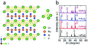
LnRuSi electrides crystallize in a tetragonal structure with the space group P4/nmm (Fig. 1a), where Ru and Si layers are separated and sandwiched by double layers of Ln. The Ln layers are composed of edge-shared Ln4 tetrahedra with a vacant space (V site) located at the center (depicted as light blue balls in Fig. 1a) that can accommodate an electron or hydrogen anion.27 The crystal quality of LnRuSi was confirmed by Rietveld refinements of the obtained powder XRD data (Fig. 1b and S1†). The 111 target phases with purity higher than 95 wt% were obtained for LaRuSi, CeRuSi and PrRuSi samples; however, the purity of NdRuSi was only as high as 83.5 wt%, and the 122 impurity phase was difficult to remove completely, even after long-time annealing. It is noteworthy that the XRD patterns show that the (00l)-orientation is favored for all ground LnRuSi powders, which indicates that the exposed surfaces of the present catalysts are dominated by (00l)-Ln/Ru/Si layers. This was confirmed by SEM measurements, as shown in Fig. S2,† where clear layered structures were observed for all LnRuSi compounds. The cleavage energy between different layers along the z direction was calculated for LaRuSi using DFT to determine the most possible exposed surface. As shown in Fig. S3,† the cleavage energy between La–La layers (0.051 eV Å−1) was much lower than that between La–Si layers (0.211 eV Å−1) and Ru–Si layers (0.312 eV Å−1). Therefore, cleavage between the La–La layers is most likely to occur during the milling process, i.e., (00l)-La terminated surfaces should be the major exposed surfaces for the hand-milled powder of LaRuSi, and accordingly, for other LnRuSi compounds.The catalytic performance for ammonia synthesis over the LnRuSi electride catalysts is shown in Fig. 2 and summarized in Table S2.† The LnRuSi catalysts exhibited much higher activity than pure Ru powder with a similar surface area (as high as 30–80 times), and were comparable to conventional iron or ruthenium based catalysts. For instance, the ammonia yield over LaRuSi was 0.492%, which was much higher than that over commercial Fe–K2O–Al2O3 (0.164%) under same operation condition.31 On the other hand, no ammonia formation was observed over the Ru-free compounds, including the LaScSi electride, LaSi and La5Si3 (Table S3†), which indicates that lattice Ru atoms in LaRuSi are the active sites for ammonia synthesis.
Moreover, present LnRuSi electrides are robust to air and water. The ammonia synthesis over LaRuSi catalysts that were stored in air for half year and treated with water for 24 h. The ammonia formation rate for these samples were 1800 and 1760 μmol gcat−1 h−1, respectively, almost identical to that for the as prepared catalyst of 1810 μmol gcat−1 h−1 (Table S4†). The XRD measurements were performed for these samples, and we did not find any clear phase change (Fig. S4†). Moreover, even after the used catalyst is stored in air for 1 year, the catalytic activity is not decreased (1780 μmol g−1 h−1) without any phase change. These observations demonstrate the excellent stability of the present catalyst.
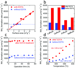
An attempt was made to increase the surface area of the LnRuSi catalysts by vigorous milling for longer times to enhance the catalytic activity. For the LaRuSi catalyst, the surface area was increased from 1.0 to 1.4 and 1.8 m2 g−1 by increasing the milling time from 0.5 to 1.0 and 2.0 h, respectively. However, the ammonia formation rates for these two samples were almost the same as that for the low surface area sample (Fig. 2a, blue symbols and Table S2†). These results suggest that the exposed Ru active sites did not change as the surface area increased. The La–La layer is most likely to be cleaved (Fig. S3†); therefore, longer milling times should result in an increase of the inactive La exposed layer rather than desired Ru layers. Therefore, although the surface area was increased, the exposure of Ru active sites was not significantly enhanced (shown schematically in Fig. S5a†), which resulted no significant change of the ammonia synthesis rates.
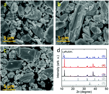
Chemical etching is one of the most powerful routes to modify the surface structure of intermetallics.32–35 For example, selective removal of Gd atoms on the surface layers was reported by etching intermetallic Pt5Gd in HClO4 solution, which led to a 5-fold increase in the oxygen reduction reaction relative to pure Pt.32 We propose that selective chemical etching with acid to remove the surface Ln and Si of LnRuSi could increase the exposure of Ru sites, which would enhance the activity for ammonia synthesis (Fig. S5b†). LaRuSi was used to determine the optimal conditions for chemical etching (Table 1). The results showed that HNO3 acid did not significantly change either the activity or surface area. XRD and SEM measurements (Fig. 3) showed that there was no phase change during HNO3 treatment. This is mainly due to the oxidation ability of HNO3, which may passivate the surface by the formation of oxides. Highly concentrated HCl acid reacted with LaRuSi rapidly; La was completely dissolved and amorphous Ru–Si and H2 were formed as the products (Fig. S6 and S7†). Although with a high surface area, the amorphous Ru–Si obtained had low catalytic activity. With diluted HCl acid (0.02 M), La could be partially removed, but the reaction was still very strong, whereby H2 was rapidly formed, and the catalytic activity was only slightly enhanced. The H2 formation rate was decreased significantly using 50% HCOOH solution, and the ammonia formation rate for the resultant sample was increased from 1100 to 1966 μmol gcat−1 h−1. These results indicate that control of the etching strength is a key factor to optimize exposure of the Ru sites. EDTA is a well-known chelating acid for fixing Ca2+, Ga3+ and La3+ ions;36–38 therefore, EDTA-2Na solution was used for the selective etching of LaRuSi. XRD measurement shows that EDTA treated LaRuSi maintained the original phase with the minor formation of hydride, while the surface was etched (see the SEM images Fig. 3 and S9†). The concentration of the EDTA-2Na solution and the etching time were changed, and the activity of the EDTA-treated LaRuSi increased linearly with the surface area, unlike the sample not treated with EDTA (Fig. 2a), which demonstrates that the present etching method is a promising route to enhance ammonia synthesis activity, and suggests that higher ammonia formation rates can be achieved when a finer catalyst powder is prepared. The optimized condition for etching was: 0.2 g LaRuSi powder with 5 mM EDTA-2Na (10 mL) for 5 h (Fig. S8,† etching time longer than 5 h did not further change the specific surface area and activity). This treatment resulted in ammonia formation rates for LaRuSi at steady state of 3020 and 5340 μmol gcat−1 h−1 at 340 °C and 400 °C, respectively (Table 2), which were approximately 3 times higher than that of the original catalyst. These reaction rates were much higher than other unloaded catalysts, such as LaCoSi,21 Co3Mo3N31 and YRu2,26 and even higher than that over the Ru/C12A7:e− catalyst.14 The same EDTA treatment process (0.2 g of catalyst placed into 10 mL of 5 mM EDTA-2Na solution for 5 h) was performed for the other LnRuSi catalysts and the etching of surfaces were confirmed by SEM measurement (Fig. S10–S12†). As shown in Fig. 2b and Table 2, the ammonia formation rates of all the catalysts were increased 2 to 4-fold by the EDTA treatment. The TOF values for LnRuSi were as high as ca. 0.06 s−1 at 400 °C, which is 600 times higher than that for pure Ru powder and much higher than other reported unloaded catalysts and even the Cs–Ru/MgO catalyst, which demonstrates the superior performance of the present catalysts.
| Entry | Acid | pH of acid solution | Etching time (h) | S BET (m2 g−1) for resultant samplea | NH3 formation rate at 400 °Cb (μmol g−1 h−1) |
|---|---|---|---|---|---|
| a The BET surface area was measured before ammonia synthesis. b The activities were recorded after holding at 400 °C for 1 h. Operation conditions: 0.1 g of catalyst at 400 °C and 0.1 MPa with H2/N2 = 45/15 mL min−1 flow. | |||||
| 1 | 1 M HNO3 | 0 | 3 | 2.9 | 1270 |
| 2 | 0.1 M HNO3 | 1 | 3 | 1.7 | 960 |
| 3 | 0.01 M HNO3 | 2 | 3 | 1.7 | 1070 |
| 4 | 1 M HCl | 0 | 3 | 274.0 | 50 |
| 5 | 0.2 M HCl | 0.7 | 3 | 92.0 | 350 |
| 6 | 0.02 M HCl | 1.7 | 3 | 5.6 | 1520 |
| 7 | 50% HCOOH | 1.08 | 3 | 2.9 | 1970 |
| 8 | 10% HCOOH | 1.68 | 3 | 2.8 | 1610 |
| 9 | 0.1 M EDTA-2Na | 4.92 | 3 | 1.5 | 1740 |
| 10 | 0.05 M EDTA-2Na | 4.92 | 3 | 1.7 | 2090 |
| 11 | 0.01 M EDTA-2Na | 4.94 | 3 | 3.3 | 4320 |
| 12 | 0.005 M EDTA-2Na | 4.96 | 3 | 4.1 | 5010 |
| 13 | 0.001 M EDTA-2Na | 5.02 | 3 | 4.9 | 3260 |
| 14 | 0.005 M EDTA-2Na | 4.96 | 0.5 | 2.3 | 3560 |
| 15 | 0.005 M EDTA-2Na | 4.96 | 1 | 2.8 | 3380 |
| 16 | 0.005 M EDTA-2Na | 4.96 | 5 | 4.0 | 5180 |
| 17 | 0.005 M EDTA-2Na | 4.96 | 11 | 4.2 | 5360 |
| 18 | 0.005 M EDTA-2Na | 4.96 | 24 | 4.1 | 5080 |
| 19 | 0.005 M EDTA-2Na | 4.96 | 30 | 4.1 | 5250 |
| 20 | Without acid | — | — | 1.4 | 1100 |
| Catalyst | S BET (m2 g−1) | r (μmol g−1 h−1) | TOFb (s−1) | E a (kJ mol−1) | Ref. | ||
|---|---|---|---|---|---|---|---|
| 340 °C | 400 °C | 340 °C | 400 °C | ||||
| a Operation condition: 0.1 g of catalyst at 0.1 MPa with H2/N2 = 45/15 mL min−1 flow. The ammonia formation rates were measured after holding at 400 °C for 24 h. b CO is not easily adsorbed on the bulk catalysts; therefore, the estimation was conducted using the surface area (SBET) and the covalent radii of active atoms, and the Wigner–Seitz radii as the averaged radii for the bulk compounds. c 0.2 g of catalyst. d 0.5 g of catalyst. e 0.4 g of catalyst. | |||||||
| LaRuSi before EDTA | 1.4 | 840 | 1810 | 0.028 | 0.060 | 40 | This work |
| LaRuSi after EDTA | 4.2 | 3020 | 5340 | 0.033 | 0.059 | 48 | This work |
| CeRuSi before EDTA | 1.6 | 770 | 1680 | 0.022 | 0.047 | 47 | This work |
| CeRuSi after EDTA | 4.0 | 2650 | 5480 | 0.030 | 0.062 | 52 | This work |
| PrRuSi before EDTA | 1.5 | 560 | 1180 | 0.017 | 0.035 | 45 | This work |
| PrRuSi after EDTA | 2.0 | 1010 | 2370 | 0.023 | 0.053 | 52 | This work |
| NdRuSi before EDTA | 1.5 | 280 | 670 | 0.008 | 0.020 | 51 | This work |
| NdRuSi after EDTA | 2.2 | 1230 | 3000 | 0.025 | 0.061 | 55 | This work |
| Ru (1.2 wt%)/C12A7:e−c | 1–2 | 1160 | 2760 | 0.083 | 0.197 | 49 | 9 |
| Ru (1.8 wt%)/C12A7:e− | 1.0 | 2020 | 0.068 | 51 | 14 | ||
| Cs–Ru (1.0 wt%)/MgOc | 12 | 2260 | 0.013 | 86 | 9 | ||
| Cs–Ru (2.0 wt%)/MgO | 12 | 3200 | 0.009 | 120 | 14 | ||
| Ru | 3.1 | 23 | 0.00009 | This work | |||
| Rud | 3.1 | 12 | 0.00005 | 26 | |||
| YRu2c | 0.7 | 490 | 0.014 | 73 | 26 | ||
| YRu2 | 6.4 | 3320 | 0.011 | 26 | |||
| Co3Mo3N | 8.5 | 800 | 0.0012 | 57 | 21 | ||
| LaCoSi | 1.8 | 1250 | 0.031 | 42 | 21 | ||
| Fe–K2O–Al2O3e | 14 | 330 | 56 | 31 | |||
Fig. 2c shows the time course for NH3 formation over LaRuSi before and after treatment with EDTA. The ammonia formation rate increased initially and then became stable for the untreated sample, while it was steady for the EDTA-treated sample. This indicated that no aggregation and/or leaching occurred during ammonia synthesis. The temperature dependence was also measured for all the LnRuSi catalysts before and after EDTA treatment (Table 2). The EDTA-treated catalysts showed much higher activity than the untreated catalysts in the range examined (260–400 °C) with similar apparent activation energies (Ea) ranging from 40 to 55 kJ mol−1 (Fig. S13†). For instance, the Ea values for LaRuSi before and after EDTA treatment were 40 and 48 kJ mol−1, respectively, which was similar to that for the electride-supported Ru catalysts.4,9,13 The reaction orders for LaRuSi before and after EDTA treatment were almost same (Table S6†). The positive hydrogen reaction order of around 0.6 indicates that the hydrogen poisoning effect was avoided via reversible hydrogen absorption/desorption over LaRuSi due to the intrinsic nature of the anionic electron.27 Fig. S14† shows the effect of pressure for the LaRuSi catalysts, where the ammonia formation rate increased approximately 2.6-fold for both samples when the pressure was raised from 0.1 to 0.9 MPa.
XRD measurements were performed for the EDTA treated LnRuSi catalysts to check the stability (Fig. S15†). For all catalysts after ammonia synthesis, the H− ions, which are crucial for the formation of ammonia,27 were incorporated and LnRuSiHx hydrides were formed as the dominant phase. Since LnRu2Si2 cannot incorporate H− ions,27 its phase should not be changed during ammonia synthesis, which was confirmed for the samples without EDTA treatment. However, the 122 phase increased slightly for the EDTA-treated catalysts after ammonia synthesis, which will be discussed later. Consequently, LnRuSiHx as the actual catalyst remained stable during ammonia synthesis for EDTA-treated catalysts, i.e., EDTA treatment did not affect the robust ability of LnRuSi electrides.
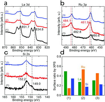
ICP-AES measurement of the solution after EDTA treatment of LaRuSi was performed. As shown in Table S7,† the dissolved species were predominantly La and Si, while only a small amount of Ru was detected (ca. 3% of La), i.e., surface La and Si were removed during the EDTA etching process, so that the Ru layer emerged to the surface. The amount of La removed was slightly higher than that of Si, which suggests the possibility for the formation of LaRu2Si2 at Si-rich sites, which was confirmed by XRD measurements (Fig. S15†). XPS measurements were also conducted to evaluate the amounts and valence states of surface species. Fig. 4 shows that the intensity of the La 3d and Si 2s signals decreased significantly after EDTA treatment, while that of Ru 3p was significantly increased. The intensities of these signals changed slightly after ammonia synthesis. Fig. 4d shows the estimated ratios of surface La, Ru and Si. The Ru ratio increased from 0.15 to 0.54 after EDTA treatment, and decreased slightly to 0.46 after ammonia synthesis, probably due to the reconstruction process. The La to Si ratio was almost constant for all three samples, which indicates that the surface La and Si layers were simultaneously removed during EDTA treatment, as supported by the ICP-AES results. Both the ICP-AES and XPS results revealed that the amount of exposed Ru sites on the surface was increased after EDTA treatment, which was the key reason for enhancement of the catalytic activity. On the other hand, the valence state of Ru was initially negative (460.6 eV present, and 461.4 eV for Ru metal); it became positive after EDTA treatment (461.9 eV) due to the partially oxidation of exposed Ru on the surface, and then returned to negative (460.8 eV) with the reduction of hydrogen during ammonia synthesis. This indicates that during ammonia synthesis, the exposed Ru was still in a negatively charged state for the EDTA-treated catalysts.
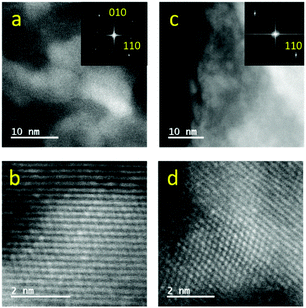
Most of the catalytic properties of LaRuSi, including the activation energy, reaction orders and pressure effect, remain unchanged before and after EDTA treatment, which suggests that the active sites for both samples are layered Ru in the negative charge state; however, the possibility for the formation of Ru nanoparticles via aggregation on the surface during reaction cannot be excluded. Therefore, HAADF-STEM measurements were performed to determine whether Ru nanoparticles were formed on EDTA-treated LaRuSi. The homogeneous lattice fringes were present in both bright and dark areas (Fig. 5), which demonstrates that there were no Ru nanoparticles on the surface. This was further supported by the FFT pictures in Fig. 5 and the selected area electron diffraction pattern in Fig. S16:† the tetragonal structure corresponding to LaRuSi lattice was clearly observed, while the hexagonal structure that corresponds to Ru metal was not observed. In addition, no Ru peaks were evident in the powder XRD measurements (Fig. S15†). Therefore, it was concluded that there were no Ru particles on the EDTA-treated LaRuSi surface.
We have recently reported that the LaRuSi electride exhibited good activity for ammonia synthesis due to its electride character; negatively charged Ru together with lattice H− ions, which can reversibly exchange with anionic electrons, are the key factors in the promotion of ammonia formation.27 A large difference in the activation energy for ammonia formation (40 kJ mol−1) and N2 isotope exchange reaction (157 kJ mol−1) indicated the strong adsorption of N2 or N atoms on the LaRuSi surface, so that N2 would be activated through the hot-atom mechanism suggested for LaCoSi.21 The heat released from adsorption leads to the simultaneous desorption of H from lattice H−, which immediately combines with adsorbed N to form NHx. The Ru–N bond is thus weakened through the hydrogenation process, and ammonia is finally formed and desorbed. However, how planar Ru in LnRuSi acts to activate N2 has not been discussed previously. It is well-accepted that terrace Ru atoms are not active for ammonia synthesis because both experiments and DFT calculations showed that the apparent activation energy for N2 dissociation at terrace sites of the Ru (0001) face was as high as 1.8–1.9 eV. Considering the large Ru–Ru distance in LnRuSi (ca. 0.30 nm, Table S8†), which differs from Ru metal or YRu2 (ca. 0.26 nm), together with the layered geometric configuration, N2 activation over LnRuSi should be different from that over conventional Ru catalysts.
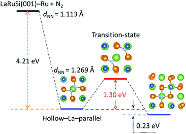
Here DFT calculations were performed to investigate how the N2 was adsorbed and activated on the LaRuSi(001)–Ru surface; the reaction path for N2 dissociation and the adsorption states are shown in Fig. 6 and S17–S19,† respectively. The most stable adsorption configuration of N2 on LaRuSi(001)–Ru is where a N2 molecule is adsorbed parallel on the hollow site of La and bonded with four surface Ru atoms, and La is beneath the surface Ru layer and centered within a square of Ru atoms (Fig. S17a†). The deformation charge density for this adsorption state (Fig. S19a†) clearly showed that electrons are transferred from Ru to N2, which weakens the N![[triple bond, length as m-dash]](https://www.rsc.org/images/entities/char_e002.gif) N triple bond with an elongated bond length (from 0.111 nm to 0.127 nm). As a result, the negatively charged nitrogen has a strong coulombic attraction with the positively charged lanthanum atom, which leads to a larger adsorption energy of −4.21 eV. The N2 dissociation barrier is 1.30 eV, and two dissociated N atoms locate at the hollow sites of La and Si with an adsorption energy of −4.44 eV (Fig. S18a†). The strong exothermic adsorption of N2 and the relatively low dissociation barrier indicate that the adsorbed N2 can be easily dissociated into N atoms without further addition of energy.21 In this model, all Ru atoms on the surface are active for ammonia synthesis. This is quite different from that of the conventional Ru catalyst. For instance, N2 activation only occurs at B5 sites in the conventional Ru catalyst, and the adsorption energies for N2 and 2 N are respectively −0.7 and −0.8 eV,17,18 which are much lower than that on the LaRuSi surface. In the conventional Ru catalyst, N2 is adsorbed perpendicular on the step site and the overall dissociation barrier is 0.4 eV with the dissociated N adsorbed at the 3-fold hcp site.19 These differences clearly demonstrate that layered Ru in LnRuSi is independent from B5 site active centers for ammonia synthesis. Further calculations and related studies to clarify the detailed reaction mechanism are in progress.
N triple bond with an elongated bond length (from 0.111 nm to 0.127 nm). As a result, the negatively charged nitrogen has a strong coulombic attraction with the positively charged lanthanum atom, which leads to a larger adsorption energy of −4.21 eV. The N2 dissociation barrier is 1.30 eV, and two dissociated N atoms locate at the hollow sites of La and Si with an adsorption energy of −4.44 eV (Fig. S18a†). The strong exothermic adsorption of N2 and the relatively low dissociation barrier indicate that the adsorbed N2 can be easily dissociated into N atoms without further addition of energy.21 In this model, all Ru atoms on the surface are active for ammonia synthesis. This is quite different from that of the conventional Ru catalyst. For instance, N2 activation only occurs at B5 sites in the conventional Ru catalyst, and the adsorption energies for N2 and 2 N are respectively −0.7 and −0.8 eV,17,18 which are much lower than that on the LaRuSi surface. In the conventional Ru catalyst, N2 is adsorbed perpendicular on the step site and the overall dissociation barrier is 0.4 eV with the dissociated N adsorbed at the 3-fold hcp site.19 These differences clearly demonstrate that layered Ru in LnRuSi is independent from B5 site active centers for ammonia synthesis. Further calculations and related studies to clarify the detailed reaction mechanism are in progress.
Conclusions
In summary, we have reported a B5-site-independent Ru catalyst, the LnRuSi electride, which exhibits good performance for ammonia synthesis. With respect to their robust durability toward acids, surface Ln and Si are removed while more Ru sites emerge by selective etching using EDTA-2Na acid, which results in a 2- to 4-fold increase in the activity compared to that of the original samples. The estimated TOFs for the LnRuSi catalysts under mild conditions (0.1 MPa, 400 °C) were approximately 0.06 s−1, which is 600 times higher than that of Ru powder. DFT calculations revealed that the specific LnRuSi structure stabilized N2 adsorption with a strong exothermic effect, which decreased the apparent activation energy for N2 dissociation. Therefore, N2 activation is much easier on the Ru plane of LnRuSi than that on conventional Ru catalysts. We propose that the present air- and acid-durable LnRuSi electride catalysts are applicable to catalytic reactions in water/acid atmospheres, in which conventional electrides do not function well. The present EDTA etching method would also be useful to enhance the activities of other noble metal-containing intermetallic catalyst systems.Conflicts of interest
There are no conflicts to declare.Acknowledgements
This work was supported by the Japan Society for the Promotion of Science (JSPS) through a Grant-in-Aid for Scientific Research (S), No. 17H06153. Y. L. is supported by the JSPS fellowship for young scientists (No. 18J00745). X. W. is supported by Ministry of Science and Technology of the People's Republic of China (MOST), No. 2018YFA0208603, No. 2016YFA0200602, National Natural Science Foundation of China (NSFC), No. 21573204, Anhui Initiative in Quantum Information Technologies (No. AHY090400), the Fundamental Research Funds for the Central Universities, National Program for Support of Top-Notch Young Professional, and External Cooperation Program of BIC CAS (211134KYSB20130017). We would like to express our appreciation to Prof. Michikazu Hara for use of the XPS instrument.Notes and references
- K. Aika, H. Hori and A. Ozaki, J. Catal., 1972, 27, 424–431 CrossRef CAS.
- Z. Song, T. H. Cai, J. C. Hanson, J. A. Rodriguez and J. Hrbek, J. Am. Chem. Soc., 2004, 126, 8576–8584 CrossRef CAS PubMed.
- N. Saadatjou, A. Jafari and S. Sahebdelfar, Chem. Eng. Commun., 2015, 202, 420–448 CrossRef CAS.
- J. Z. Wu, Y. T. Gong, T. Inoshita, D. C. Fredrickson, J. J. Wang, Y. F. Lu, M. Kitano and H. Hosono, Adv. Mater., 2017, 29, 1700924 CrossRef PubMed.
- K. Aika, K. Shimazaki, Y. Hattori, A. Ohya, S. Ohshima, K. Shirota and A. Ozaki, J. Catal., 1985, 92, 296–304 CrossRef CAS.
- H. Bielawa, O. Hinrichsen, A. Birkner and M. Muhler, Angew. Chem., Int. Ed., 2001, 40, 1061–1063 CrossRef CAS PubMed.
- J. J. Mortensen, B. Hammer and J. K. Nørskov, Phys. Rev. Lett., 1998, 80, 4333–4336 CrossRef CAS.
- K. Aika, Catal. Today, 2017, 286, 14–20 CrossRef CAS.
- M. Kitano, Y. Inoue, Y. Yamazaki, F. Hayashi, S. Kanbara, S. Matsuishi, T. Yokoyama, S. W. Kim, M. Hara and H. Hosono, Nat. Chem., 2012, 4, 934–940 CrossRef CAS PubMed.
- Y. Inoue, M. Kitano, S. W. Kim, T. Yokoyama, M. Hara and H. Hosono, ACS Catal., 2014, 4, 674–680 CrossRef CAS.
- S. Kanbara, M. Kitano, Y. Inoue, T. Yokoyama, M. Hara and H. Hosono, J. Am. Chem. Soc., 2015, 137, 14517–14524 CrossRef CAS PubMed.
- M. Kitano, S. Kanbara, Y. Inoue, N. Kuganathan, P. V. Sushko, T. Yokoyama, M. Hara and H. Hosono, Nat. Commun., 2015, 6, 6731 CrossRef CAS PubMed.
- Y. F. Lu, J. Li, T. Tada, Y. Toda, S. Ueda, T. Yokoyama, M. Kitano and H. Hosono, J. Am. Chem. Soc., 2016, 138, 3970–3973 CrossRef CAS PubMed.
- M. Kitano, Y. Inoue, H. Ishikawa, K. Yamagata, T. Nakao, T. Tada, S. Matsuishi, T. Yokoyama, M. Hara and H. Hosono, Chem. Sci., 2016, 7, 4036–4043 RSC.
- C. J. H. Jacobsen, S. Dahl, P. L. Hansen, E. Törnqvist, L. Jensen, H. Topsøe, D. V. Prip, P. B. Møenshaug and I. Chorkendorff, J. Mol. Catal. A: Chem., 2000, 163, 19–26 CrossRef CAS.
- W. Raróg-Pilecka, E. Miśkiewicz, D. Szmigiel and Z. Kowalczyk, J. Catal., 2005, 231, 11–19 CrossRef.
- K. Honkala, A. Hellman, I. N. Remediakis, A. Logadottir, A. Carlsson, S. Dahl, C. H. Christensen and J. K. Nørskov, Science, 2005, 307, 555–558 CrossRef CAS PubMed.
- A. Lógadottir and J. K. Nørskov, J. Catal., 2003, 220, 273–279 CrossRef.
- S. Dahl, A. Logadottir, R. C. Egeberg, J. H. Larsen, I. Chorkendorff, E. Törnqvist and J. K. Nørskov, Phys. Rev. Lett., 1999, 83, 1814–1817 CrossRef.
- L. Diekhöner, H. Mortensen, A. Baurichter, A. C. Luntz and B. Hammer, Phys. Rev. Lett., 2000, 84, 4906–4909 CrossRef PubMed.
- Y. T. Gong, J. Z. Wu, M. Kitano, J. J. Wang, T. N. Ye, J. Li, Y. Kobayashi, K. Kishida, H. Abe, Y. Niwa, H. S. Yang, T. Tada and H. Hosono, Nat. Catal., 2018, 1, 178–185 CrossRef.
- T. N. Ye, Y. F. Lu, J. Li, T. Nakao, H. S. Yang, T. Tada, M. Kitano and H. Hosono, J. Am. Chem. Soc., 2017, 139, 17089–17097 CrossRef CAS PubMed.
- M. Armbrüster, K. Kovnir, M. Friedrich, D. Teschner, G. Wowsnick, M. Hahne, P. Gille, L. Szentmiklósi, M. Feuerbacher, M. Heggen, F. Girgsdies, D. Rosenthal, R. Schlögl and Y. Grin, Nat. Mater., 2012, 11, 690–693 CrossRef PubMed.
- M. Armbrüster, R. Schlögl and Y. Grin, Sci. Technol. Adv. Mater., 2014, 15, 034803 CrossRef PubMed.
- L. Piccolo, L. Kibis, M. C. de Weerd, E. Gaudry, J. Ledieu and V. Fournée, ChemCatChem, 2017, 9, 2292–2296 CrossRef CAS.
- T. Ogawa, Y. Kobayashi, H. Mizoguchi, M. Kitano, H. Abe, T. Tada, Y. Toda, Y. Niwa and H. Hosono, J. Phys. Chem. C, 2018, 122, 10468–10475 CrossRef CAS.
- J. Z. Wu, J. Li, Y. T. Gong, M. Kitano, T. Inoshita and H. Hosono, Angew. Chem., Int. Ed., 2019, 58, 825–829 CrossRef CAS PubMed.
- A. Ellaboudy, J. L. Dye and P. B. Smith, J. Am. Chem. Soc., 1983, 105, 6490–6491 CrossRef CAS.
- R. H. Huang, M. K. Faber, K. J. Moeggenborg, D. L. Ward and J. L. Dye, Nature, 1988, 331, 599–601 CrossRef CAS.
- S. Matsuishi, Y. Toda, M. Miyakawa, K. Hayashi, T. Kamiya, M. Hirano, I. Tanaka and H. Hosono, Science, 2003, 301, 626–629 CrossRef CAS PubMed.
- R. Kojima and K. Aika, Appl. Catal., A, 2001, 218, 121–128 CrossRef CAS.
- M. Escudero-Escribano, A. Verdaguer-Casadevall, P. Malacrida, U. Grønbjerg, B. P. Knudsen, A. K. Jepsen, J. Rossmeisl, I. E. L. Stephens and I. Chorkendorff, J. Am. Chem. Soc., 2012, 134, 16476–16479 CrossRef CAS PubMed.
- L. Wang and Y. Yamauchi, J. Am. Chem. Soc., 2013, 135, 16762–16765 CrossRef CAS PubMed.
- W. Zhang, Y. Y. Zhao, V. Malgras, Q. M. Ji, D. M. Jiang, R. J. Qi, K. Ariga, Y. Yamauchi, J. Liu, J. S. Jiang and M. Hu, Angew. Chem., Int. Ed., 2016, 55, 8228–8234 CrossRef CAS PubMed.
- Y. C. Pi, Q. Shao, X. Zhu and X. Q. Huang, ACS Nano, 2018, 12, 7371–7379 CrossRef CAS PubMed.
- G. A. Elgavish and J. Reuben, J. Am. Chem. Soc., 1976, 98, 4755–4759 CrossRef CAS.
- S. Harada, Y. Funaki and T. Yasunaga, J. Am. Chem. Soc., 1980, 102, 136–139 CrossRef CAS.
- M. R. Zhang, F. Hou, Z. G. Wang, S. H. Zhang and G. B. Pan, Appl. Surf. Sci., 2017, 410, 332–335 CrossRef CAS.
Footnotes |
| † Electronic supplementary information (ESI) available. See DOI: 10.1039/c9sc01539f |
| ‡ These authors contributed equally. |
| This journal is © The Royal Society of Chemistry 2019 |

