Liquid mobility on superwettable surfaces for applications in energy and the environment
Songnan
Zhang†
ad,
Jianying
Huang†
 b,
Zhong
Chen
 c,
Shu
Yang
 d and
Yuekun
Lai
 *ab
*ab
aNational Engineering Laboratory for Modern Silk, College of Textile and Clothing Engineering, Soochow University, Suzhou 215123, China. E-mail: yklai@suda.edu.cn; yklai@fzu.edu.cn
bCollege of Chemical Engineering, Fuzhou University, Fuzhou 350116, China
cSchool of Materials Science and Engineering, Nanyang Technological University, 50 Nanyang Avenue, Singapore 639798, Singapore
dDepartment of Materials Science and Engineering, University of Pennsylvania, 3231 Walnut Street, Philadelphia, PA 19104, USA
First published on 21st November 2018
Abstract
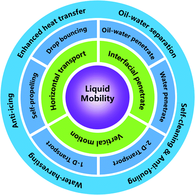
Liquid mobility on super-wettable materials is of interest for enhanced heat transfer, self-cleaning, anti-fouling, anti-icing, water-harvesting, and oil–water separation. Here, we review different mechanisms related to liquid mobility on super-wettable materials, encompassing some classical wetting theories and liquid transport behaviors observed on biological surfaces with special textures. Then, the different categories of liquid behaviors on super-wettability materials are summarized, focusing on recent progress on vertical motion (droplet self-propelling and bouncing), horizontal transportation (transportation on one-dimensional (1D) and two-dimensional (2D) materials), and interfacial penetration (oil–water penetration and water penetration). Along these lines, we also review the latest applications in energy and the environment, followed by presenting the outlook and key challenges.
1. Introduction
In 1805, Thomas Young first introduced liquid wetting theory on a smooth solid surface.1 Wenzel and Cassie–Baxter then proposed theoretical models describing wetting on rough and heterogeneous surfaces in 1936 and 1944, respectively.2–4 Subsequently, Rosano stated a theoretical model of the sliding angle on a flat surface in 1951.5 Despite these early theories, it was not until recently that researchers started to realize that nature has produced many different types of special wettability that can be perfectly described by these theories. Barthlott found that the lotus leaf possesses a special self-cleaning functionality due to its special structure and superwettability.6 Since then, more and more creatures with special superwettability have been found and investigated, such as cicada wing, butterfly wing, rice leaf, mosquito compound eyes, water strider, pitcher plants, and so on.7–12 Meanwhile, inspired by such creatures with special functionality, materials with superwettability have attracted extensive attention in the last two decades. Based on special superwettability materials, liquid mobility has been studied by a number of researchers, including vertical bouncing, horizontal transportation, and interface penetration.Liquid mobility is a significant topic in various industrial and chemical engineering fields, including heat transfer enhancement, self-cleaning, anti-fouling, anti-icing, water-harvesting, and oil–water separation. Boerhaave found that when a water droplet is dropped on a hot substrate with a very high temperature, the droplet will bounce off and roll away because of the participation of an integral air cushion between the underlying substrate and impinging droplet. This phenomenon was investigated by Leidenfrost and subsequently other researchers with the aim of controlling directional droplets bouncing, enhancing the heat transfer, and increasing the critical temperature at which this phenomenon named after Leidenfrost occurs.13 On the other hand, a droplet bouncing on a substrate without heating was first systematically investigated by Richard and his coworkers, when they studied the duration of a droplet in contact with the substrate.14 Since then, scientists have investigated ways to decrease the contact duration of a bouncing droplet. Inspired by some special creatures' features, such as cicada wing, lotus leaf, and shark skin,6,7 researchers have focused their investigation on the mechanism of water droplet self-propulsion, transportation, and penetration through the surfaces with special structures. Success has been achieved in fabricating smart materials for directional liquid mobility. Impressive advances have been made in bionic materials research in terms of the fundamental understanding and potential applications in environmental energy fields and human healthcare.
To understand liquid mobility on special superwettability materials, it is significant to comprehend its intrinsic mechanisms before investigating the phenomenon of liquid mobility. Therefore, in this review, we first cover the mechanisms of liquid wettability on surfaces, which is further divided into two parts: the theories of liquid wetting on flat and rough surfaces and the theory of liquid sliding on a tilted surface. As for the theories of liquid wetting, we focus on three models, namely the Young's contact model, Wenzel model, and Cassie model. As for the theory of liquid sliding, we focus on the Rosano model.
Next, the principles of liquid transport behaviors on biological surfaces are introduced in detail. We principally review some gradients that exist on the creatures with distinct surface structural characteristics for directional liquid mobility. These include the Laplace gradient and surface energy gradient and special aligned textured surfaces.
Then importantly, we focus on the influencing factors for different types of liquid mobility, covering vertical motion, horizontal transportation, and interfacial penetration. Vertical motion is further divided into droplet self-propelling and droplet bouncing. Coverage of horizontal transportation focuses on the motion on 1D and 2D materials, while interface penetration includes oil–water penetration and water-only penetration based on the differences between the mixtures.
We then cover the mechanism of droplet mobility by looking into the surface wettability and performing driving force analysis. Following this, we summarize some typical applications that require special liquid mobility, including heat transfer enhancement, anti-icing, self-cleaning, antifouling, water-harvesting, and oil–water separation. Finally, we present the outlook in research into biomimetic materials with special liquid mobility.
2. Mechanisms of liquid wettability on surfaces
2.1 Theories of liquid wetting on flat and rough surfaces
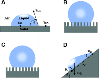
The liquid contact angle is a measure of equilibrium between solid–liquid, solid–gas, and gas–liquid interfacial energies when a liquid droplet is placed on a solid surface. Herein, we present three classical theories, namely Young's model, Wenzel's model, and Cassie's model. | (1) |
 | (2) |
Subsequently, Cassie and Baxter developed a new model in 1944 considering an inhomogeneous surface. Assuming that the liquid–gas contact angle was 180°, they proposed that the water droplet contact angle on a rough solid surface (θ*) when air is trapped inside the surface asperity is given be the simple rule of a mixture:2
cos![[thin space (1/6-em)]](https://www.rsc.org/images/entities/char_2009.gif) θ* = fSL θ* = fSL![[thin space (1/6-em)]](https://www.rsc.org/images/entities/char_2009.gif) cos cos![[thin space (1/6-em)]](https://www.rsc.org/images/entities/char_2009.gif) θ + (1 − fSL)cos θ + (1 − fSL)cos![[thin space (1/6-em)]](https://www.rsc.org/images/entities/char_2009.gif) 180° = fSL 180° = fSL![[thin space (1/6-em)]](https://www.rsc.org/images/entities/char_2009.gif) cos cos![[thin space (1/6-em)]](https://www.rsc.org/images/entities/char_2009.gif) θ + fSL − 1 θ + fSL − 1 | (3) |
2.2 Theory of liquid sliding on a tilted surface
When a droplet is not in an equilibrium state, for example, on a moving droplet on a slope, the contact angle hysteresis (Δθ) can be defined as a characteristic parameter:| Δθ = θA − θR | (4) |
mg![[thin space (1/6-em)]](https://www.rsc.org/images/entities/char_2009.gif) sin sin![[thin space (1/6-em)]](https://www.rsc.org/images/entities/char_2009.gif) α = σw(cos α = σw(cos![[thin space (1/6-em)]](https://www.rsc.org/images/entities/char_2009.gif) θR − cosθA) θR − cosθA) | (5) |
3. Principles of liquid transport behaviors on biological surfaces
Many plants and animals have evolved with functional surfaces demonstrating unique (non)wettability. Examples will be given next of droplets moving directionally on these surfaces, as driven by the Laplace gradient, surface energy gradient, special aligned textured surfaces, and so on.3.1 Laplace gradient and surface energy gradient
Inspired by spider silk (Fig. 2A) and cactus cones (Fig. 2C),15,16 researchers found that the surface energy gradient and Laplace pressure play crucial roles in affecting the liquid mobility on 1D structures. As for the special surfaces, due to the difference in surface roughness, the tension on both sides of the contact line between the water droplet and the surface is unbalanced, thus generating a driving force for water droplets to move to the direction with a decreasing contact angle. This force by surface energy gradient (Fig. 2B and D), is given by:17,18 | (6) |
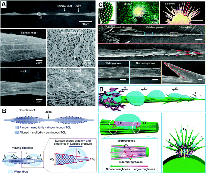 | ||
| Fig. 2 (A) The SEM image of spider silk, (B) the mechanism of droplet mobility on spider silk, reproduced with permission.15 Copyright 2010, Nature. (C) The SEM image of cactus, (D) the mechanism of droplet mobility on cactus, reproduced with permission.16 Copyright 2012, Nature. | ||
For spider silk and the conical cactus spine, the Laplace gradient is the other driving force for the directional transport of a water droplet, which originates from spider silk with the spindle-shaped knots and the conical cactus spine with the aligned grooves, respectively. As for the droplet on the surface with the Laplace gradient, the corresponding difference in Laplace pressure can be denoted as:19,20
 | (7) |
Nepenthes alata (Fig. 3A and B) enables directional continuous liquid transport on its special surface due to its hierarchical micro–nanostructured grooves (Fig. 3C–E). The asymmetric grooves with a wedge-shaped blind hole optimize and strengthen the capillary in the transport direction, and prevent backflow in the opposite direction. As discovered by Chen et al. (Fig. 3F–H), a droplet can be transported from the inside to the outside, while the droplet on the outer edge cannot move inside. Through observation, they found that water transport is confined within a single large channel, with large channels distributed perpendicular to the edge of the rim region, while the lateral flow of water does not exceed the width of the original deposition zone. As shown in Fig. 3I, when the microcavity was filled to a water level beyond the top of its side wall, the water would wrap around the starting point of the area that overlapped the next microcavity. The lower aqueous layer (III) then overflowed to produce an upper aqueous layer (II), whereby the upper aqueous layer then filled the second microcavity; this cycle was repeated before filling the second microcavity, and the upper aqueous layer (II) then overflowed to produce the top water layer (I), with the top water layer then filling the third microcavity. In this way, the sequential filling of each microcavity resulted in a continuous delivery of water, while the retention of water prevented wetting in the opposite direction.12
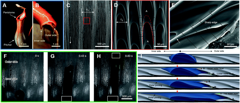 | ||
| Fig. 3 (A) Optical image of the Nepenthes alata's pitcher and peristome. Scale bar: 5 cm. (B) Cross-sectional optical image of the peristome from the inner side to outer side. Scale bar: 1 cm. The SEM image of: (C) two first-order microgrooves and D) approximately ten second-order microgrooves arranged on each first-order microgroove. The scale bars are 500 μm and 50 μm, respectively. (E) The SEM image of duck-billed microcavity with arch-shaped edges. Scale bar: 20 μm. (F–H) Water droplet transportation from the inside to the outside along a single large channel. Scale bar: 500 μm. (I) 3D simulation for the process of water droplet transportation. Reproduced with permission.12 Copyright 2016, Nature. | ||
3.2 Liquid transport on special aligned textured surfaces
Apart from the Laplace gradient and surface energy gradient, we can also find droplets moving directionally on aligned textured surfaces, such as butterfly, shorebirds and Namib desert beetle.Zheng et al. found that the droplet could easily roll down from the butterfly's wings along the radial outward (RO) direction of the central axis without wetting the butterfly's body. They found that these special abilities are attributed to the numerous micro–nano scales periodically overlapped covering the wings and thereon the fine lamella-stacking nano-stripes, as shown in Fig. 4B and C. This highly directional micro–nano structure allows water droplets to easily roll away in the radial direction but not in the opposite direction, as shown in Fig. 4D and E. Especially, these two opposite states can be switched by tuning the posture of the flapping and the direction of air passing through the surface. As shown in Fig. 4F, the mechanism of the distinct adhesion is that the droplet on the butterfly's wing shows different wetting states in different inclined directions of the wing. In case of the tilted downward direction, the separation of the ordered nano-tips on the nano-stripes and micro-scales induced water droplets to deposit on the wing with a Cassie-like state and to form an extremely discontinuous three-phase contact line (TCL). Therefore, a droplet could roll down from the surface easily. When the inclined direction was upward, the close arrangement of nano-tips and micro-scales pinned the droplet on the surface with a Wenzel-like state and formed a quasi-continuous TCL. This anisotropic adhesion allows the butterfly wings to be directionally cleaned in a humid environment and ensures the stability of the butterfly when flying without dust accumulation.8
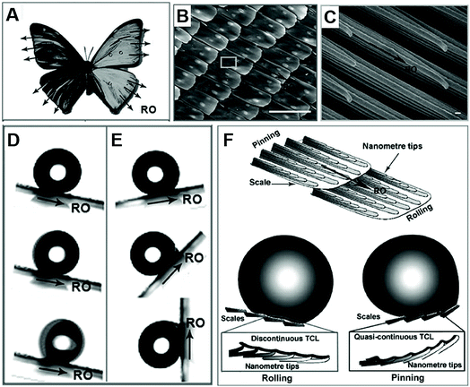 | ||
| Fig. 4 (A) The optical photo of a butterfly, and the SEM images of (B) the scales with micro-/nanostructures periodically overlapped covering on the wings (scale bars: 100 μm) and (C) thereon fine lamella-stacking nano-stripes (scale bars: 100 nm). (D) The water droplet easily rolls away in the radial outward direction, but (E) firmly embed in the opposite direction, even fully upright. (F) The theoretical simulation for potential mechanism of these distinct adhesion. Reproduced with permission.8 Copyright 2007, The Royal Society of Chemistry. | ||
Assessing droplet transportation on the shorebird's surface, Prakash et al. performed thorough research, as shown in Fig. 5A. They found that the droplet could stepwise move from the tip of its beak to its mouth by the bird repeatedly opening and closing its beak. As shown in Fig. 5B and C, they found that droplets advanced toward the narrower area with a constant speed first, then accelerated when they were close to the top of the wedge. They investigated that the drop was pinned for regions θa > θ1 > θ2 > θr, marked by the red line. When α > αbreak, the drop breaks eventually. The ratcheting regime is indicated in green and the optimal ratchet by the red arrows. For αopen > αbreak, the drop breaks, whereas for αclose < αclose min, the drop spills from the beak, as shown in Fig. 5D.21
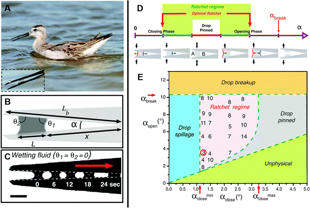 | ||
| Fig. 5 (A) Photo of a juvenile Wilson's phalarope feeding, the inset is a fluid droplet in a horizontal beak. (B) Schematic diagram of a bird beak with a fluid droplet trapped between the upper and lower mandibles. (C) A completely wetting droplet of silicone oil self-propels toward the apex of a mechanical bird beak with a constant opening angle. Scale bar, 2 mm. (D) Schematic illustration of the droplet dynamics in an oscillating bird beak. (E) Regime diagram for droplet transport in an oscillating mechanical bird beak illustrating the dependence of the system's behavior on the minimum and maximum opening angles αclose and αopen > αclose, respectively. Reproduced with permission.21 Copyright 2008, Science. | ||
In the Namib desert, some beetles (Fig. 6A) can survive by water-harvesting dew water from air. As shown in Fig. 6B and C, Parker et al. reported that the elytra of such beetles were covered in a near-random array of smooth bumps with no covering (Fig. 6B) and acted as the hydrophilic seeding points of the peaks, where fog settled and formed fast-growing droplets that pin to the elytra, starting the first process. In another aspect, due to the troughs, including their sloping sides, there was a covering of the microstructure coated in wax (Fig. 6B) with arranged regular hexagonal flattened hemispheres (Fig. 6C), whereby the surface created a superhydrophobic area. In the second process, water striking the hydrophobic slopes could also be collected, even though it may bounce or be blown to a hydrophilic region, but when this no-collected water reaches a critical size, the ratio of water's mass to its surface contact area is increased rapidly until the capillary force to the surface is overcome. Finally, the droplet is detached and rolls down the tilted beetle's surface to its mouthpart, guided by other peaks along its path.22
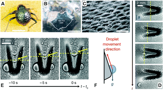 | ||
| Fig. 6 (A) Dorsal optical picture of an adult desert beetle surface, covered with numerous peaks and troughs. (B) SEM image of depressed areas of the otherwise black elytra are stained positively (waxy, colored), whereas the peaks of the bumps remain unstained (wax-free; black). (C) SEM image of the textured surface with arranged regular hexagonal flattened hemispheres. Scale bars, (A) 10 mm; (B) 0.2 mm; (C) 10 μm. Reproduced with permission.22 Copyright 2001, Nature. (D and E) Time-lapsed optical images of condensed water droplets on an asymmetric bump rotated (D) 180° and (E) 90° relative to gravity. (F) Schematic diagram of droplet movement direction. Reproduced with permission.23 Copyright 2016, Nature. | ||
4. Liquid mobility with different orientations on superwettability materials
As shown in Fig. 7, we divide liquid mobility into vertical motion, horizontal transport, and interface penetration. Researchers have investigated vertical motion from two aspects: droplet self-propelling and droplet bouncing. As for the horizontal transportation, scientists have focused their researches on the driving force of motion on 1D materials and 2D materials. Interface penetration research includes oil–water penetration and water penetration. All these studies can be applied in the field of oil–water separation, self-cleaning, anti-fouling, water-harvesting, anti-icing, and enhanced heat transfer.4.1 Vertical motion
 | (8) |
 | (9) |
| ΔEs = σlvΔA | (10) |
 | (11) |
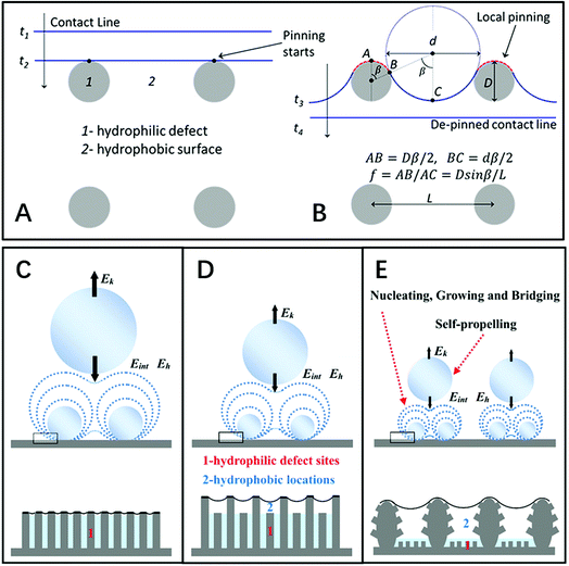 | ||
| Fig. 8 (A and B) Diagram of the contact line locomotion on a hydrophobic surface “2” with hydrophilic defects “1” on the square-array substrate. Reproduced with permission.27 Copyright 2012, American Chemical Society. (C–E) Schematic diagrams of droplets self-propelling with different sizes and densities on three types of structures with different dynamic wettabilities: (C) nanostructure surface, (D) irregular nanostructure surface, and (E) hierarchical surface. Reproduced with permission.30 Copyright 2016, Wiley-VCH Verlag GmbH & Co. KGaA, Weinheim. | ||
Herein, based on the theoretical study of the coalescence-induced droplet movement, Nam et al. suggested that about half of the released surface energy was converted to kinetic energy in the course of coalescence.36 Nevertheless, combining detailed measurements of droplet self-propelling with numerical modelling of droplets coalescence, Wang and co-workers believed that only less than six percent of the excess surface energy could be converted to translational kinetic energy. Their research illustrated the action of the internal fluid dynamics in the course of the droplet coalescence and supported the exertion of systems that can control propelling droplets.31 Additionally, they demonstrated that the production of wetting states is caused by conquering the energy barriers as a result of nucleation-mediated droplet–droplet interactions, which provides an idea for optimizing the surface.37
Through regulating the roughness, coating with bionic nanofilms, and designing the nanostructured surfaces, researchers have achieved desired functional surfaces with the ability of droplet self-propelling.38–45 Recent literature has indicated that hierarchical superhydrophobic surfaces (SHOSs) have a superior functionality of droplet self-propelling.30,41,46–48 Through experiments and comparison with nanostructured surfaces, Zhang et al. demonstrated that the self-propelling movement parameters, such as the velocity and critical size of self-propelling droplet, depend on adhesive force and roughness to some extent.48,49 Theoretical experimental results demonstrate that hierarchical SHOSs have the most superior condensate microdroplet self-propelling (CMDSP) functionality due to the lowest adhesion and highest roughness.34
To effectively obtain dropwise condensation and enhance the ability of droplet self-propelling, condensate must be quickly removed from the surface, which contributes to enhancing the heat transfer coefficient of materials.
Three-dimensionless parameters are often used in the fundamental research on droplet bouncing.59 The first is the Weber number (We), which is the ratio of the inertial force to the surface tension. When the Weber number is smaller than 1.0, it means the surface tension plays a significant role. When the Weber number surpasses 1.0, it means the effect of surface tension is negligible. The second parameter is the Reynolds number (Re), which is the ratio of the inertia force to the viscosity force. When the Reynolds number is small, it indicates the viscosity influence is higher, and vice versa. The third parameter is the Ohnesorge number (Oh), which is approximately the ratio of viscous forces to the product of inertial and surface tension forces. Related formulae are shown below.
 | (12) |
 | (13) |
 | (14) |
The velocity and viscosity play indispensable roles in deciding the wetting states of an impinging droplet to be either completely pinned, partially or entirely bounced, or even splashed.60–62 For a droplet with a low We, the impact is quasi-elastic with a minor-scale deformation due to the insignificant energy dissipation. For large We and Re, the droplet tends to splash into two or more secondary disintegrated droplets.51,53,59,61 Based on dimensionless parameters,60,62–68 Quéré et al. found that the kinetic energy of the impacting droplets is dissipated by viscosity in the course of impact in a viscous-inertial system,64 where the maximum diameter obeys Dmax ∼ D0Re1/5.69,70 As for a viscous droplet, Schroll et al. simulated the impact of a viscous liquid droplet onto a smooth dry substrate. Since the ambient air pressure was negligible, droplets with several m s−1 impacting speed would not produce a splash. Due to the action of the boundary layer produced by the droplet impacting, the falling droplet would be flattened into a spatially uniform thin pancake shape.67 Therein, the pancake ejection was subject to the impacting speed and liquid viscosity.66 As for the capillary-inertial system, the kinetic energy of the impacting droplet could be entirely converted into surface energy,14 where the maximum diameter obeys Dmax ∼ D0We1/2 or We1/4.64 Recently, Visser et al. observed that no splashing happened for droplet diameters between 12 and 100 μm with an impacting speed up to 100 m s−1. Compared with previous available models, the experimental result corresponds with the Pasandideh-Fard model,71 in which the boundary layer dynamics has a significant impact on the droplet spreading. Utilizing the model input value with an initial contact angle of 180°, they confirmed that the air layer was present underneath the impinging droplet, which was further verified by de Ruiter et al., who presented a universal bouncing mechanism that the air film could occur continuously on both wetting and nonwetting surfaces for a droplet with a moderate impacting speed.65
The contact time, defined as the time from the beginning of the droplet impacting on the substrates to the ending of bouncing off the surfaces, can be used to characterize the droplet dynamic. In 2002, Quéré et al. measured the contact duration between a droplet and the substrate, then quantified the performance of superhydrophobic surfaces.14 As for a droplet impacting on superhydrophobic surfaces, its inertial-capillary nature can be considered, but its viscosity effects are not important and can be ignored. Balancing inertia (ρR/τ2) with capillarity (γ/R2), the contact duration obeys:14,72
 | (15) |
The contact time is linearly correlated with R3/2 in the range of droplet radius from 0.1 mm to 4.0 mm, and has no correlation with the impacting speed from 20 cm s−1 to 230 cm s−1 but increases in this range below 10 cm s−1 because of the drop's weight (Fig. 9A).14,72
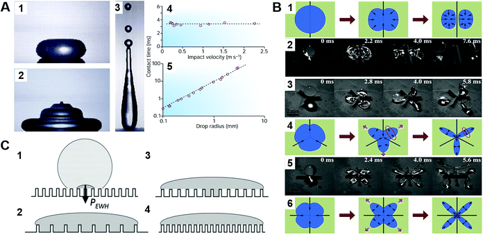 | ||
| Fig. 9 (A) Mechanism of a droplet impacting and bouncing on the substrate surface. (1–3) the process of droplet impacting, recoiling, and bouncing, respectively. (4–5) The function diagram of the impacting droplet contact time with the impacting speed and droplet radius. Reproduced with permission.14 Copyright 2002, Nature Publishing Group. (B) Droplet impacting processes on superhydrophobic surfaces with different macrotextures. Reproduced with permission.77 Copyright 2015, AIP Publishing LLC. (C) The wetting states of impacting droplets based on different relative magnitudes of the wetting and antiwetting pressures. Reproduced with permission.81 Copyright 2009, American Institute of Physics. | ||
Noteworthily, compared with the contact duration of the inertia-dominant spreading stage, the duration of the recoiling stage accounts for a large proportion with about 70–80% of the total contact duration. Bartolo et al. divided the recoiling stage into two regimes: a viscous regime and inertial regime. Herein, the droplet recoiling rate (Vret/Dmax) depends on the viscous force and surface tension forces.73 As for the inertial regime, the recoiling rate obeys eqn (16) according to the Taylor–Culick approach,74,75 where τi and θr represent the inertial time and the receding contact angle, respectively; as for the viscous regime, the retraction rate obeys eqn (17):53,73
 | (16) |
 | (17) |
Researchers have demonstrated that the time during impacting and bouncing depends on wetting hysteresis and the solid fraction.76,77 Using superhydrophobic surfaces, Bird et al. managed to reduce the contact time below the theoretical limit. This was due to the redistribution of the liquid mass, thereby altering the drop hydrodynamics.50 Similarly, Quéré and co-workers significantly changed the hydrodynamics by creating a macrotexture to maximize the water repellence and minimize the contact time between the solid and liquid even further.78 Shen et al. observed that the impacting droplet was disintegrated into several smaller portions in the presence of the “cross-shaped” macrotextures, and the recoiling process could be completely integrated into the spreading process to give the maximal deformation, resulting in a much shorter overall contact duration of approximately 5.5 ms (Fig. 9B).77 Meanwhile, Wang and co-workers found that pancake bouncing on the surface experienced a deep penetration and detachment, but did not experience the process of retraction. This allows a fourfold reduction in contact time on superhydrophobic surfaces, due to the rectification of capillary energy stored in the penetrated liquid into upward motion adequate to lift the drop.79 Soon after, they discovered that a droplet impacting on Echevaria leaves displays asymmetric bouncing dynamics with different spreading and retraction along two directions, and they attributed this phenomenon to the concave/convex architecture of the cylindrical leaves. Furthermore, they concluded that the contact time could have a ∼40% reduction, owing to the asymmetric momentum and mass distribution caused by the preferential fluid pumping around the drop rim.80
An irreversible wetting state transition between the Cassie state and Wenzel state will cause the absence of the anti-adhesive phenomenon corresponding with superhydrophobicity.81–91 Presently, the mechanism for the wetting state transition is still under discussion. Inspired by the research of Lafuma and Quéré,88 researchers focused on a smart structure design to avoid the irreversible wetting state transition.83 Through utilizing a superhydrophobic rough specimen with a two-level hierarchical structure, Quéré et al. achieved Cassie regime stabilization and water repellency enhancement. Additionally, they verified the optimal conditions for the structure design to achieve droplet bouncing without satellite ejection and confirmed that the critical value of the We number for the satellite ejection is about 160, which is lower than that of a hydrophobic flat surface (We number of about 700) and hydrophilic surface (We number > 1000). Additionally, they emphasized the significance of the air film in minimizing the viscous dissipation, and demonstrated that the conditions of pinning would occur when the velocity obeys:89
 | (18) |
 | (19) |
 | (20) |
| PWH = kρVC | (21) |
From the above review, it is clear that the roughness and wetting transition significantly affect the bouncing performance, including causing direction alteration and contact time reduction. Let us not forget that the substrate temperature also affects the bouncing performance. As observed by Leidenfrost, when the water droplets are placed on a hot substrate, droplets will bounce and roll around on the substrate before they are evaporated. The air cushion between the underlying substrate and impinging droplets is a key factor behind this observation,13 and the air cushion can be stabilized through the control of the phase-change process. When the substrate temperature T is above the liquid's boiling point, the droplet may experience three different regimes, as shown in Fig. 10A–C, depending on the competition between the Leidenfrost temperature and substrate temperature. The three regimes are contact boiling (contacts the surfaces and boils immediately), gentle film boiling (forms a Leidenfrost vapor layer without any surface contact and bounces back), and spraying film boiling (both forms a Leidenfrost layer and ejects tiny droplets upward). Tran et al. experimentally determined the conditions under which impact behaviours in each regime can be realized as shown in Fig. 10D.56
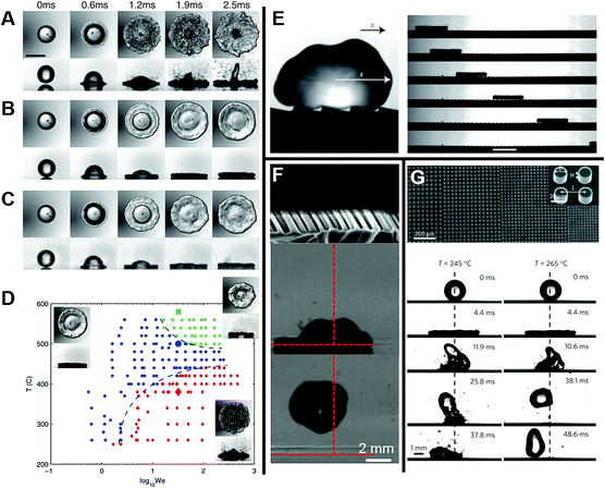 | ||
| Fig. 10 Series of bottom-view and side-view images of representative water droplet impacts in three regimes: (A) contact boiling, (B) gentle film boiling, (C) spraying film boiling. (D) Phase diagram for water droplet impact on a heated surface showing three separate regions: contact boiling regime (red solid diamonds), gentle film boiling regime (blue solid circles), and spraying film boiling regime (green solid squares). Reproduced with permission.56 Copyright 2012, American Physical Society. (E) A drop deposited on a hot ratchet self-propels in the direction indicated by the arrow. Reproduced with permission.97 Copyright 2011, Nature. (F) Cross-sectional SEM image of tilted nanopillar arrays and the corresponding images of water droplet impact and subsequent rebound. Reproduced with permission.98 Copyright 2013 American Chemical Society. (G) Scanning electron microscopy (SEM) image of the gradient surface and the corresponding vectored propulsion of an impinging droplet for temperatures T = 245 °C and 265 °C, respectively. Reproduced with permission.99 Copyright 2016, Macmillan Publishers Limited. | ||
So far, researchers have successfully fabricated various substrates covered with microstructures,100–102 nanostructures,103–105 and micro- & nanostructures106–109 to intensify heat transfer via enhancing the Leidenfrost temperature. Utilizing surfaces covered with carbon nanofibers, Hrudya et al. found that it delayed the transition to film boiling to much higher temperatures compared to smooth surfaces. The vapor flow cools the small scale of the carbon fibers before the liquid impacts, thus enhancing the Leidenfrost temperature.103 It was also found that the size of the microstructures or micro- and nanostructures has a significant effect on the Leidenfrost temperature.101,102
Utilizing a Leidenfrost droplet, researchers have developed various substrates to investigate directional droplet transport. Quéré's group found remarkably mobile model hovercrafts, whereby the droplet placed on a hot ratchet not only levitates, but also self-propels in a well-defined direction, as shown in Fig. 10E. This is attributed to the asymmetric textures rectification effect on the vapor flow escaping below the Leidenfrost body.97
As for these macro- and microscale ratchet structures, the vapor flow is dominant and the Leidenfrost droplet moves against the tilted direction,110–115 whereas for the surfaces with tiny features, droplets move along the tilted direction, as shown in Fig. 10F.98,116,117 Asymmetric wettability of nanostructured surfaces was found to have induced the observed directional rebound of droplets in the transition boiling regime.98 Liu et al. found that tilting silicon nanowires surfaces can be utilized to transport a drop directionally at high temperature through regulating its surface characteristics. Superhydrophilic surfaces covered with tilting silicon nanowires with moderate lengths were found to display anisotropic wetting performance at high temperature. Surfaces with enhanced chemical hydrophobicity or covered with short tilting silicon nanowires showed high-temperature non-wetting performance, and thus failed in driving the drop transport directionally. Superhydrophilic surfaces with long tilting silicon nanowires caused the deposited drops to boil violently and were not suitable for directional drop transport at high temperature.117
It is challenging to control and induce the motion of highly mobile droplets toward specific locations without affecting the heat transfer efficiency. Wang's group reported that the wetting symmetry of a droplet could be altered at high temperature by generating two concurrent thermal states (Leidenfrost and contact-boiling) on a topographically patterned surface, thus leading to a preferential motion of a droplet toward the region with a higher heat transfer coefficient, as shown in Fig. 10G. This is beneficial for some applications, such as tuneable control of directional fluid flow, varying heat transfer, and modification of the critical Leidenfrost temperature.99
4.2 Horizontal transportation
Fca = r·4πbγ![[thin space (1/6-em)]](https://www.rsc.org/images/entities/char_2009.gif) sin(π − α) sin(π − α) | (22) |
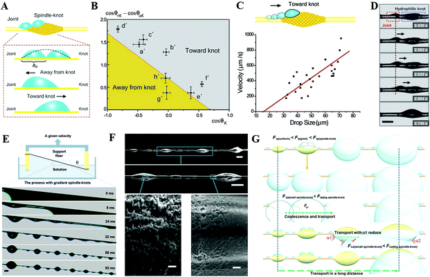 | ||
Fig. 11 (A) Analysis diagram of forces that can drive tiny water droplets away from and toward knot. (B) The functional relationship between static contact angle (cos![[thin space (1/6-em)]](https://www.rsc.org/images/entities/char_2009.gif) θK) on the spindle-knots and the difference which is between receding and advancing contact angles (cos θK) on the spindle-knots and the difference which is between receding and advancing contact angles (cos![[thin space (1/6-em)]](https://www.rsc.org/images/entities/char_2009.gif) θrK − cos θrK − cos![[thin space (1/6-em)]](https://www.rsc.org/images/entities/char_2009.gif) θaK). (C) Functional relationship diagram between the velocity toward knot and the drop size on the fiber with the rough spindle-knot. (D) The motion of tiny water droplets on the fiber with the rough spindle-knot. Reproduced with permission.118 Copyright 2010, WILEY-VCH Verlag GmbH & Co. KGaA, Weinheim. (E) Schematic diagram of the whole fabrication process. (F) SEM images of bioinspired fibers with gradient spindle-knots with various scales. (G) Mechanism illustration of the water droplets transportation in a long distance. Reproduced with permission.125 Copyright 2013, Nature. θaK). (C) Functional relationship diagram between the velocity toward knot and the drop size on the fiber with the rough spindle-knot. (D) The motion of tiny water droplets on the fiber with the rough spindle-knot. Reproduced with permission.118 Copyright 2010, WILEY-VCH Verlag GmbH & Co. KGaA, Weinheim. (E) Schematic diagram of the whole fabrication process. (F) SEM images of bioinspired fibers with gradient spindle-knots with various scales. (G) Mechanism illustration of the water droplets transportation in a long distance. Reproduced with permission.125 Copyright 2013, Nature. | ||
4.2.2.1 Unidirectional line-pattern surface. The movements of liquids resulting from unbalanced surface tension forces constitute an important surface phenomenon, known as the Marangoni effect.126 When regulated properly, these types of flows are valuable in several industrial applications. Apart from the variations in temperature or composition on a liquid surface, the surface tension heterogeneity on a solid substrate can also induce the usual Marangoni motions. Due to the surface tension gradient, the motion of droplets can be directional and controllable.
Bliznyuk et al. created anisotropic patterns with stripes of alternating wettability (Fig. 12A) through lithography to investigate the motion of droplets. By altering the relative widths of the stripes, the fraction of the hydrophobic area was varied to ensure an energy gradient that could induce the motion of the droplets, as shown in Fig. 12B. The fraction of the hydrophobic area α can be described as:
 | (23) |
 | (24) |
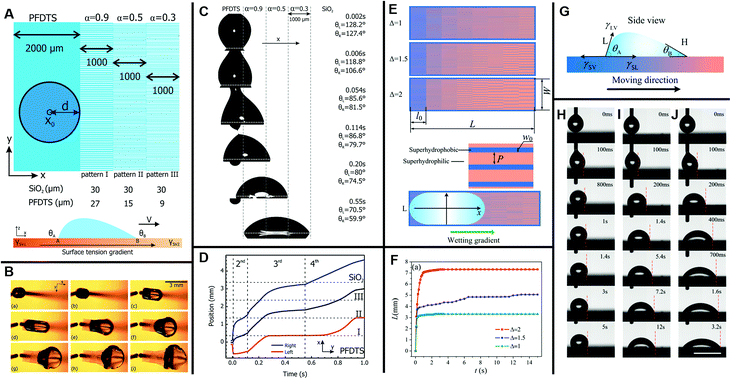 | ||
| Fig. 12 (A) Schematic diagram of the gradient pattern design and surface tension gradient on a silicon slice. Hydrophobic (blue) and hydrophilic areas (white) are PFDTS SAMs and bare SiO2, respectively. (B) The movement of a glycerol/water droplet with a volume of 2 μL on a surface with subsequent pattern gradient α = 0.9, 0.5, 0.3. (C) The side view picture of droplet displacement snap shots on the corresponding pattern gradient surface (d = 0.36 mm). (D) The displacement variation of the left (receding) and right (advancing) boundaries over time; the center position stands for the average of both boundaries. Reproduced with permission.127 Copyright 2011, American Chemical Society. (E) Three designed samples of unidirectional stripes on a photomask. Blue and orange stripes stand for superhydrophobic and superhydrophilic areas, respectively. (F) The displacement variation over time on three surfaces with different wettability-patterned gradients. (G) Side view diagram for a droplet standing on a wettability-patterned gradient surface. (H–J) Snap shots of the water droplet movement on three unidirectional stripe-patterned gradient surfaces, respectively. The scale bars for all figures are 5 mm. Reproduced with permission.128 Copyright 2017, The Royal Society of Chemistry. | ||
4.2.2.2 Radial inward- and outward-pattern surface. Apart from the unidirectional wettability-patterned gradients, radial wettability is also reported for some specific applications, such as water-harvesting. Different from the two-dimensional random motion of merging droplets, Daniel et al. designed a radially outward chemical gradient through a diffusion-controlled silanization method to guide the otherwise random motion of droplets, as shown in Fig. 13A–D. Due to the hysteresis, the driving force of the droplet movement could be gained from the difference in the equilibrium contact angles at points B and A, as shown in Fig. 13E. Additional driving force is provided by the coalescence with the adjacent droplets that nucleate and grow prior to the primary droplet formation. Powered by these driving forces, water droplets (0.1 to 0.3 mm) could be transported with a velocity hundreds to thousands of times faster than that of typical Marangoni flows. The enhancement of the heat transfer coefficient on the surface with a chemical gradient, as shown in Fig. 13F, could be applied to heat exchangers and heat pipes.18 Similarly, Hong developed a controlled oxidation reaction to fabricate radially inward wettability gradient surfaces with hydrophilic centers and hydrophobic exteriors, which is a little different from Daniel's radially outward gradient surfaces.18 Due to the coalescence of dewdrops and the wettability gradient, water droplets moved toward the hydrophilic center and went through the collected hole, which could be applied for water-harvesting.130
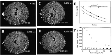 | ||
| Fig. 13 (A–D) Snap shots of fast water droplets movements (displayed by the plume-like and streak-like patterns) on a silicon slice with a radial wettability gradient. (E) The contact angles (θa: advancing contact angle; θr: receding contact angle) variation as a function of time. (F) The diagram of heat transfer coefficient for the siliconized copper surface (solid circle) and the chemical gradient copper surface (hollow circle) as a function of subcooling. Reproduced with permission.18 Copyright 2001, Science. | ||
Furthermore, different from the circle pattern with inward or outward wettability gradients, Bai et al. successfully prepared surfaces with various shaped wettability patterns to compare the fog-harvesting performance, as shown in Fig. 14A. They found that surfaces with a star-shaped pattern possessed more efficient fog harvesting than other uniform surfaces, such as superhydrophilic, superhydrophobic, and circle patterns (Fig. 14B–E). Additionally, surfaces with a smaller pattern size were found to be more efficient than the ones with a larger pattern size of the same pattern. The finding means that both the shape and size of the pattern are crucial for the liquid directional transport and thus the water collection efficiency.131
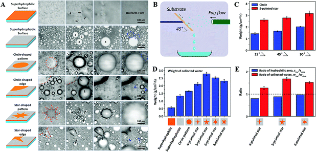 | ||
| Fig. 14 (A) Snap shots of the fog-harvesting process on surfaces with different wettability patterns. (B) Schematic illustration of the strategy to measure the fog-harvesting performance on different surfaces. (C) Comparison diagram of the fog-harvesting efficiency on circle and 5-pointed star patterns with different tilting angles. (D) Comparison diagram of fog-harvesting efficiency on surfaces with various wettabilities. (E) Ratios of hydrophilic area and collected water on 4-, 5-, 6-pointed star patterned surfaces, respectively. Reproduced with permission.131 Copyright 2014, Wiley-VCH Verlag GmbH & Co. KGaA, Weinheim. | ||
4.2.2.3 Directional transportation on bio-inspired Nepenthes alata surface. The pitcher plant is known for its subtle pitcher cage that can easily capture insects due to its well-designed trap with a slippery peristome. Inspired from that, scientists have gradually focused their eyes on the biomimetic artificial peristome surface of the pitcher plant for its water-collecting functionality. Recently, exploiting two typical lithography strategies, Jiang's group fabricated novel microgrooves with a concave array at their bottom. Through the test of the concave outline's effect on asymmetrical liquid spreading, they found that the arch-shaped outline and sharp rim on the concave edge were crucial for the directional liquid spreading.132 Thereafter, they proposed and demonstrated a spontaneous overflow-controlled liquid unidirectional transportation mechanism using the peristome-mimicking surface. Liquids with varied surface tensions and viscosities could spontaneously propagate in a single preferred direction and pin in all the others, which is different from the canonical predictions for completely wetting liquids spreading symmetrically on a high-energy surface.133 These functionalities of fast, long-distance, and unidirectional transportation on the biomimetic surface could be applied in many fields, like fog-harvesting, nonpowered drug delivery, and self-lubrication.
4.3 Interface penetration
Apart from the vertical motion and horizontal transportation, interface penetration is another form of liquid mobility. As a mode of motion from front side to back side along the vertical direction, interface penetration can be applied for oil–water separation. Recently, directional liquid penetration through the porous materials has been investigated by several research groups, as illustrated below.4.3.1.1 Superhydrophobic–superoleophilic wettability. A membrane surface that has superhydrophobic–superoleophilic wettability is used for oil–water separation, where oil or water can selectively wet and pass through the membrane.134–148
Tian et al. reported a stable superhydrophobic and superoleophilic coating based on a stainless steel mesh with an aligned ZnO nanorod array-coated mesh film (Fig. 15A). As shown in Fig. 15B, the treated mesh film displays both superhydrophobic (Fig. 15B1) and superoleophilic (Fig. 15B2) properties, which can make oil spread over the coated membrane quickly and breakthrough easily. When a certain kind of liquid stands on the film surface, its meniscus is stable. Attributed to the surface curvature, its intrinsic contact angle θ can be sustained wherever the position of the three-phase contact line is (as shown in Fig. 15C). Once external pressure works, a liquid like water cannot penetrate the film spontaneously when θ > 90° due to the static pressure ΔP > 0. Whereas when θ < 90° due to the static pressure ΔP < 0, the mesh film cannot sustain any pressure, and a liquid like oil can penetrate the film spontaneously. As for the surface with aligned ZnO nanorod arrays, the structured film can increase the advancing contact angle of a water droplet, and decrease that of an oil droplet on the surface, which makes the penetration more efficient. Through comparison as shown in Fig. 15D, Tian et al. found that the pore size plays a significant role in the level of hydrophobicity. They found the surface of aligned ZnO nanorod arrays with pore size of 50 μm was optimal for the desirable superhydrophobicity.145
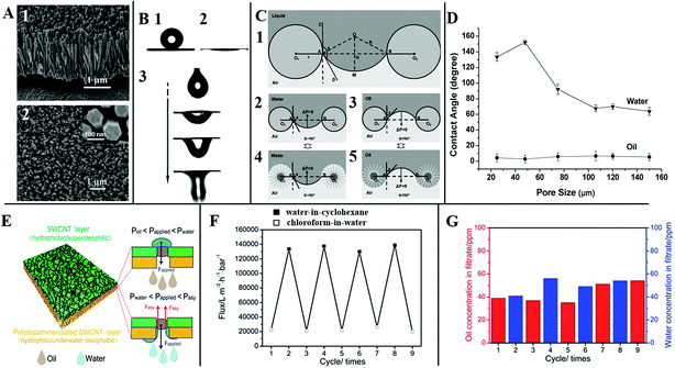 | ||
| Fig. 15 (A) The view of the aligned ZnO nanorod array-coated stainless steel mesh film, (1) the side view, (2) the top view. (B) Special surface wettability, (1) water droplet, (2) liquid paraffin oil, (3) the dynamic process of an oil droplet penetrating through the mesh film. (C) Theoretical model of the liquid wetting on the surface with aligned ZnO nanorod arrays. (D) The water and oil contact angles on the surface with aligned ZnO nanorod arrays as a function of the pore size. Reproduced with permission.142 Copyright 2011, the Owner Societies. (E) The schematic structure of an ultrathin bilayer membrane, and the corresponding pressure response mechanism diagram for oil–water separation, (F) the switchable penetration flux keeps stable after several cycles, (G) water (blue bar) and oil (red bar) concentration in the filtrate. Reproduced with permission.135 Copyright 2015, The Royal Society of Chemistry. | ||
Membranes that have asymmetric wettability can be an excellent material for liquid penetration. Hu et al. constructed bilayer membranes made of a polydopamine-coated single-walled carbon nanotube layer (SWCNTs) and a covered SWCNT layer. When Poil (the intrusion pressure of oil) < Papplied (the applied pressure difference across the membrane) < Pwater (the intrusion pressure of water), the hydrophobic–superoleophilic surface could efficiently separate a surfactant-stabilized water-in-oil emulsion. As for a higher Papplied (Pwater < Papplied < Pasy), the cooperative effect of dual layers could achieve the capability of separating the surfactant-stabilized oil-in-water emulsion (Fig. 15E). As shown in Fig. 15F and G, such ultrathin bilayer membranes display ultrahigh penetration flux and separation efficiency with excellent antifouling for controlled single-system oil–water emulsion separation by simply adjusting Papplied.135
4.3.1.2 Superhydrophilic–superoleophobic and superhydrophilic–underwater superoleophobic wettability. Inspired by the shark skin with the self-cleaning functionality enabled by underwater superoleophobicity, researchers have focused more attention on the other typical mechanism of oil–water separation, namely Superhydrophilic–superoleophobic and superhydrophilic–underwater superoleophobic wettability.149–163
By depositing titanium oxide nanoparticles onto fabric, Zheng et al. fabricated micro- and nanoscale hierarchical-structured superhydrophilic fabric films with underwater superoleophobicity. As shown in Fig. 16A–D, due to the superhydrophilicity of the scaly nanostructured titanium oxide film, water can spread and wet the fabric film without air bubbles on the membrane surface. When an oil–water mixture was poured onto the fabric film (Fig. 16E–G), the scaly fabric film could absorb water to achieve saturation rapidly in all regions of the contact before the oil could wet the film. Therefore, the water penetrates the film rapidly, while the oil is left on the film due to the excellent superoleophobicity in water. This experiment verifies the scaly titanium-oxide-coated fabric films possess the functionality of effective oil–water separation. Whereas as for the original fabric, the oil can gradually wet the fabric with some air bubbles and penetrate through these regions attributed to the superoleophilicity of the fabric in air. Therefore, the original fabric without the coating does not possess the ability of effective oil–water separation.163
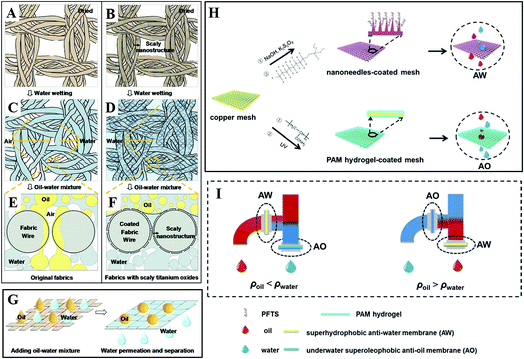 | ||
| Fig. 16 Schematic diagrams of wetting mechanism for an oil–water mixture separation on fabrics with two different films: original film and scaly nanostructured film. (A, C and E) Original film. (B, D and F) Titanium-oxide-coated nanostructured film. (A and B) Dried fabrics. (C and D) Fabrics after water wetting. (E and F) Cross-sectional analysis diagrams of the oil and water wetting process on fabrics with the original and titanium-oxide-coated nanostructured films. (G) Schematic diagrams of the oil–water mixture separation process. Reproduced with permission.163 Copyright 2015, American Chemical Society. (H) Schematic and (I) setup of an integrated dual-membrane separation system. Reproduced with permission.164 Copyright 2016, The Royal Society of Chemistry. | ||
However, traditional single membrane devices with oil–water separation functionality have inherent limitations when dealing with different kinds of oil in water. Liu et al. designed an integrated oil–water separation system, consisting of a superhydrophobic oxidized copper mesh with an anti-water (AW) function and a polyacrylamide (PAM) hydrogel-coated superhydrophilic copper mesh with an anti-oil (AO) function, as shown in Fig. 16H. They integrated two membranes into a two-outlet pipe equipment (Fig. 16I) and investigated the efficiency of different kinds of oil–water separation. When the oil density was smaller than that of water (ρoil < ρwater), the configuration of AO membrane and AW membrane was placed on the lower and higher outlet, respectively, which benefitted the heavier water to sink and penetrate through the AO membrane below, meanwhile lighter oil floated and penetrated through the upper AW membrane. If the oil was heavier than water (ρoil > ρwater), the placement of the two membranes could be simply swapped. Compared with traditional single membrane devices with oil–water separation functionality, such a functionally integrated system achieved the continuous synchronized separation of oil and water, which significantly increased the separation efficiency.164
4.3.1.3 Stimuli-responsive wettability. Apart from the above main mechanisms of liquid penetration, stimuli-responsive wettability is worthy of attention. The simulation may come from surface tension,165,166 electric field,167 light,168,169 pH,170 and temperature.171–173
Manipulating the surface tension of nanofibrous membranes to lie between the intrinsic wetting thresholds (IWTs) of the two organic liquids to be separated, Wang et al. endowed the nanofibrous membranes with superlyophobicity and superlyophilicity for the two liquids, and thus successfully separated the liquids. As shown in Fig. 17A, when the surface tension of the membrane (γsv) was precisely manipulated to be γsv(A)IWT > γsv > γsv(B)IWT), the membrane was lyophobic for liquid A and lyophilic for liquid B. After roughing the membrane, the nanofibrous membranes could be endowed with superlyophobicity and superlyophilicity, respectively, thus enabling the successful separation of liquid A and liquid B. When γsv > γsv(A)IWT, the membrane was lyophilic for the liquid (left, model of liquid A); whereas when γsv < γsv(B)IWT, the membrane was lyophobic for the liquid (right, model of liquid B). This strategy is significant to separate any immiscible liquids efficiently and may lead to the development of membranes with a large capacity, high flux, and high selectivity for organic reactions or liquid extraction in chemical engineering.166
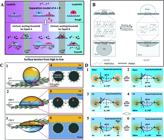 | ||
| Fig. 17 (A) Schematic illustration of the mechanism of penetration by manipulating the surface tensions, reproduced with permission.166 Copyright 2015, Wiley-VCH Verlag GmbH & Co. KGaA, Weinheim. (B) Mechanism diagram of reversible transformation for intermolecular hydrogen bonding and intramolecular hydrogen bonding, reproduced with permission.172 Copyright 2013, Wiley-VCH Verlag GmbH & Co. KGaA, Weinheim. (C) Mechanism diagram of oil–water separation process on the polyaniline mesh induced by different electric fields, reproduced with permission.167 Copyright 2016, Wiley-VCH Verlag GmbH & Co. KGaA, Weinheim. (D) Schematic mechanism diagrams of the photoinduced oil–water separation. Reproduced with permission.169 Copyright 2012, The Royal Society of Chemistry. | ||
Utilizing symmetric poly(methyl methacrylate-b-N-isopropylacrylamide) (PMMA-b-PNIPAAm), Xue et al. endowed the block copolymer (BCP) membrane with reversible and switchable wettability between hydrophilic–oleophobicity and hydrophobic–oleophilicity in different temperature ranges. Utilizing the method of direct casting, they achieved a BCP-based steel mesh with a temperature-controlled dual switch that could regulate the access of oil or water. As shown in Fig. 17B, when the solution temperature was below the low critical value, intermolecular hydrogen bonds with water triggered and generated a hydrated and swollen PNIPAAm, providing a high proportion of water content on the surface. Due to the hydrophilic behavior of both PNIPAAm and PMMA, the entire surface was hydrophilic with water wetting, which effectively blocked the penetration of oil. When the temperature was above the low critical value, intramolecular hydrogen bonds triggered and generated a dehydrated and collapsed PNIPAAm. So PNIPAAm was hydrophobic and PMMA stayed hydrophilic. With increasing temperature, PNIPAAm shrinks, but still with a large surface area. Thus, the BCP membrane was hydrophobic. For underwater oil, PMMA is oil-preferred, while the partially dehydrated PNIPAAm is oil-repellent, and still possesses a high percentage of water. After the BCP were self-assembled into a stratified structure, PNIPAAm was located between the nanoscale hard walls of PMMA. The dehydration degree of PNIPAAm can be quite high with the participation of nanoscale PMMA, and then the nano PNIPAAm domains become more oleophilic. Thus, the BCP membrane was oleophilic. This mechanism can be applied into the film for controllable oil–water separation.172
Using an electric field, Zeng et al. achieved selective water penetration using a stainless-steel mesh. Such a micro/nanoscale hierarchical-structured polyaniline mesh was superhydrophobic and underwater superoleophobic, covered with root-like polyaniline nanofibers. As shown in Fig. 17C, water in the Cassie state can hardly penetrate the superhydrophobic mesh without applied voltage. Meanwhile, oil also keeps away from the mesh because of its underwater superoleophobicity. When the applied voltage is 160 V, the water–air interface starts to sag, then water can penetrate the mesh slightly with the electric capillary pressure (ECP) increasing, while oil still stays above the mesh. Once the applied voltage reaches 170 V, water in the Cassie state transforms to the Wenzel state and penetrates the mesh, whereas oil still keeps staying over the mesh due to its underwater superoleophobicity. Therefore, once the ECP exceeds the membrane hydrostatic pressure to water, the oil–water separation of electric field induction will be realized, opening a possibility for controlled oil–water separation.167
Additionally, based on a photoinduced mechanism, researchers have also developed controllable oil–water separation. Tian et al. fabricated a switchable superhydrophobic–superhydrophilic and underwater superoleophobic aligned ZnO nanorod arrays membrane. Using this kind of material, they achieved superior controllability and separation efficiency for various oil–water mixtures in an oil–water–solid three-phase system. As shown in Fig. 17D, when the storage is in the dark, ΔP > 0, water cannot penetrate the membrane in air. Under UV irradiation, ΔP < 0, water will penetrate the membrane in air, and wet the nanostructured membrane completely. When oil is in the dark, ΔP < 0, it will penetrate the membrane in air. Once UV is irradiated, ΔP > 0, oil cannot penetrate the film in the oil–water–solid three-phase system.169 This kind of membrane with underwater superoleophobicity is able to prevent the oil pollution effectively, which thus holds great promise in photoinduced oil–water mixture treatment.
Based on a 3D cooperative hydrophobic–hydrophilic system, Cao et al. reported a continuous fog collector, consisting of a hydrophilic cotton absorbent and hydrophobic copper mesh. As shown in Fig. 18A and C, when the fog droplets form on the single hydrophobic copper mesh, they condense on the copper mesh hump first and then start to grow gradually and coalesce with the adjacent condensates to form a bigger droplet, finally covering the mesh surface completely. While as for the Janus system, once the collected droplet contacts the hydrophilic backside (Fig. 18B and D), it would simultaneously penetrate through the system and vacate the area for new condensation. Such a mechanism not only allows continuous water collection, but also decreases the surface water re-evaporation rate. Such a Janus fog system (Fig. 18E and F) has been verified to be a continuous process for fog-water harvesting.174
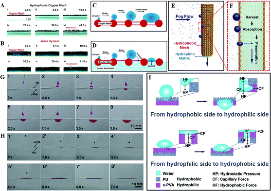 | ||
| Fig. 18 (A–B) The fog-harvesting dynamic process on: (A) a horizontal single hydrophobic copper mesh, (B) Janus system. (C–D) Schematic diagram about the process of condensate on: (C) copper mesh and (D) Janus system. (E) The front-view and (F) the cross-section diagram for the fog-harvesting process on the Janus collector, reproduced with permission.174 Copyright 2015, Wiley-VCH Verlag GmbH & Co. KGaA, Weinheim. (G) Snapshots of water droplets penetration through the upward hydrophobic PU side. (H) Snapshots of water droplets penetration through the upward hydrophilic c-PVA film side. (I) Mechanism of unidirectional water penetration on a heterogeneous wettable composite film. Reproduced with permission.177 Copyright 2012, The Royal Society of Chemistry. | ||
Additionally, using an electrospray method, Wu et al. successfully prepared a “water diode” membrane, comprised of a hydrophobic polyurethane (PU) and hydrophilic cross-linked poly (vinyl alcohol) (c-PVA). Such a device exhibited a distinct wettability difference and an excellent unidirectional water penetration functionality. Using this material, they found water could permeate spontaneously from its hydrophobic area to a hydrophilic area (Fig. 18G), but there was no occurrence of this permeation once the film was turned over (Fig. 18H). As illustrated in Fig. 18I, water droplets on the PU-upward hydrophobic area are under two opposing forces, one is hydrostatic pressure (HP), the other one is hydrophobic force (HF), which resists the water downward permeation provided by HP. With increasing water volume, the HP increases while the HF remains constant. As a result, water goes deeper. When the permeation depth reaches the PU membrane thickness, water will touch the lower hydrophilic c-PVA membrane, and continuous permeation will occur by the capillary force (CF) and the HP. However, for the water droplets on the c-PVA-upward hydrophilic area, it spreads to a thin membrane with capillarity action. When the water droplet reaches the interface of c-PVA and PU, further water permeation will not occur due to the HF prevention provided by the porous PU membrane.177 Similar with Lin et al.'s investigation,178 they found that regulating the thickness of the film plays a crucial role in deciding the unidirectional water transport capability, which may be of benefit for the various applications of novel “smart” textiles.
5. Application of liquid mobility
5.1 Enhanced heat transfer
As a high-efficiency energy-transport strategy, vapor–liquid phase-change heat transfer has been applied in thermal management, air conditioning, power generation, and waste-heat exploitation etc. There are two common types of condensation, namely film-wise condensation and drop-wise condensation. Drop-wise condensation on the hydrophobic surfaces is typically ten times more efficient in phase-change heat transfer than film-wise condensation, resulting from efficient coalescence-induced propelling, which can be realized through the released excess surface energy in the course of microdroplets coalescence without any external forces. Whereas as for film-wise condensation on the hydrophilic surfaces, gravity-induced shedding is the dominant mechanism but is usually not efficient: only when the condensate diameter comes up to the capillary length can it then slide off.179Nowadays, researchers focus more attention on the enhancement of heat transfer. Based on the fabrication of materials (inorganic oxides, silicon, polymers, and metal, etc.) with condensate microdroplet self-propelling ability, large breakthroughs have been made in enhancing heat transfer. Gao's group prepared a surface of clustered copper hydroxide ribbed-nanoneedles to achieve an over 125% enhancement in the drop-wise condensation heat transfer (DCHT) coefficient. Later on, they achieved over 89% enhancement in the DCHT coefficient on copper-based ultrathin nickel nanocone films. Utilizing the well-established top-down micro- and nanofabrication technologies, many researchers have managed to achieve the enhancement of heat transfer using silicon micro- or nanostructures (e.g., nanoneedles,180 nanocones,181 micropillars182,183 and micropyramids184), hierarchically structured porous aluminum,48 copper oxide surfaces,185 titanium-based surfaces,30 and scalable graphene coatings.186
5.2 Self-cleaning and anti-fouling
Self-cleaning and anti-fouling technology have been developed since the late 20th century, and some achievements have been made by researchers to develop practical applications. Inspired by lotus leaf, rice leaf, cicada wing, butterfly wing, snail shell, fish scale, shark skin, pitcher plant, and gecko, self-cleaning and anti-fouling technology are very broad and have been applied in many fields, varying from window glasses to solar cell panels.6,8,12,187–189 At present, self-cleaning and anti-fouling surfaces can be divided into several categories, i.e., superhydrophobic surface, superhydrophilic surface, hydrophilic and oleophobic-in-water surface, and dry self-cleaning surface.190 Special wettability and droplet mobility are crucial factors in deciding the efficiency of self-cleaning and anti-fouling.For the superhydrophobic surfaces, the self-cleaning function traditionally results from the removal of the contaminated particles by rolling water droplets, usually under an external force, such as gravity. If the contaminants are removed autonomously by the condensate self-propelled jumping motion, driven by the released surface energy from the condensate microdroplets coalescence as discussed before, the self-cleaning will be more efficient.7 Therefore, how to design a micro- or nano construction of the material's surface is crucial. Techniques to produce superhydrophobic surfaces not only need a rough surface but also one with a low surface energy. However, low surface energy matters, such as fluorosilicone polymers and fluoropolymers, are harmful to human beings and the environment, and easily lose their functionality during application. Novel environmentally friendly materials are required in future research. As for the superhydrophilic surfaces, it is mainly based on the special photoinduced properties, such as photocatalysis and photoinduced superhydrophilicity, to achieve a self-cleaning property through chemically breaking down organic dirt and mechanically washing away other dirt on the surface.191 Different from the above-mentioned superhydrophobic and superhydrophilic surfaces, dry self-cleaning is an intrinsic property of a nanostructured surface inspired from gecko setal, occurring by an energetic disequilibrium between the adhesive forces attracting a dirt particle to the substrate and those attracting the same particle to one or more spatula. Whereas once materials are fouled by oil, the hydrophilic and oleophobic-in-water surface can efficiently resist the oil to penetrate through the self-functionalized wettability surface.
5.3 Anti-icing
Ice accumulation on solid surfaces is a common occurrence in winter, which can cause serious problems for road, aviation, cables, shipping, and some energy equipment. In the past few decades, researchers have developed a variety of anti-icing techniques to reduce the formation of ice, and to reduce ice adhesion. A full process of freezing on a superwettability surface includes steps of self-jumping, bouncing, wetting in the liquid phase, and ice nucleating, bridging in the solid phase.At present, research on anti-icing coatings is focused on two general strategies, namely lotus leaf-like superhydrophobic coatings and slippery liquid-infused surfaces.192 Recent studies have shown that the surface ice nucleus adhesive force is closely related to surface wetting, as expressed in the contact angle, receding angle, wetting hysteresis, and dynamic hydrophobicity.193–195 Generally, surface chemistry and morphology are combined to realize the required icephobicity.196 The dipping method, vapor deposition method, or spraying method are mostly utilized to achieve low surface energy. The second strategy, liquid-infused layered coatings, including the oil-infused slippery liquid-infused porous surface (SLIPS) and aqueous-infused SLIPS, have aroused a lot of attention since Aizenberg and co-workers fabricated a slippery, ice-phobic surface on aluminium surfaces. SLIPS can not only significantly decrease water accumulation due to the timely sliding of condensate droplets before freezing, but can also easily remove the ice accretion and melted water through the action of gravity force at a low tilting angle.197 However, due to the high coating porosity, the weak mechanical properties pose great constraints to the application of SLIPS. New strategies are necessary in the future research.
5.4 Water-harvesting
Water pollution and a shortage of clear water cause serious health and social problems in many countries. To obtain clean water, fog collection has attracted widespread attention in research in recent years. Technically, the process includes water condensation, coalescence, transportation, and storage.198 Therefore, the mobility of water droplets plays a significant role in the efficiency of water-harvesting.During the investigation on superwettability in recent years, scholars have proposed many strategies to fabricate materials with fog-harvesting ability. Inspired by the spider silk, researchers have constructed a number of one-dimensional artificial spider silks through different methods,199 such as dip-coating method, electro-dynamic method, micro-fluid method, and fluid-coating method.118–125,200–208 Inspired by the cactus, various 1D bioinspired cactus structures have been fabricated,198 using a magnetic particle-assisted molding method, chemical or electrochemical erosion method, electrospinning with the sacrificial template method, mechanical punching, and the template replica method.209–221 For 2D materials, researchers have developed a variety of technologies through biomimetic methods, such as photolithography, mechanical micro-milling, composite technology, stimulus-trigger materials fabrication, and inkjet printing technology.131,222–226
5.5 Oil–water separation
During oil exploitation and transportation, the occurrence of oil leakages and spills can seriously cause soil and water pollution, and can then threaten the health of humans and other species. Therefore, how to effectively solve such problems has become a top priority in oil–water separation research. Currently, for the investigation of oil–water separation, researchers mainly focus on porous materials with special wettability, i.e., superhydrophobicity–superoleophilicity, superhydrophilicity–superoleophobicity, superhydrophilicity–underwater superoleophobicity and stimuli-responsive wettability.227 Therefore, how to design materials with special wettability is significant to the enhancement of the oil–water separation efficiency.At present, scientists have designed various structure on various materials, such as textile,134,152 stainless steel mesh,139,149,150,153,154,157 copper mesh,155,164 sponges,136,137,143 foams,144,151 wood,159 and hydrogels.156,158 Lai's group systematically investigated the fabrication on textile. Using a facile one-step hydrothermal strategy, they fabricated flower-like hierarchical TiO2 micro/nanoparticles onto cotton fabric substrates, and successfully achieved materials with functionalities for self-cleaning, laundering durability, and oil/water separation.228 Subsequently, they chose a facile and green dip-coating method to deposit an organically modified silica aerogel thin film onto the fabrics, followed by a polydimethylsiloxane (PDMS) coating to obtain a highly robust porous network on the fibers with excellent anti-fouling, self-cleaning ability, and highly efficient oil–water separation.229 Furthermore, they improved the method to fabricate non-particle and friendly transparent surface, and likewise achieved excellent versatile oil–water separation.230–232
6. Conclusions
In summary, different types of liquid mobility on superwettable surfaces have been reviewed, including vertical motion, horizontal transportation, and interfacial penetration based on materials with different wettability attributes. Attention has been focused on the mechanisms of liquid mobility, and the applications including enhancement of the heat-transfer coefficient, strengthening water-harvesting efficiency, suppressing or delaying ice formation, improving oil–water separation, and self-cleaning capabilities.Inspired by bio-organisms with superwettabilities, there have been significant efforts to create synthetic materials and to investigate the factors that influence liquid mobility. Nevertheless, the field of directional liquid mobility is still in the early stage. At present, a main topic in the vertical liquid motion is directional self-propelling: how to reduce the contact time on a superhydrophobic substrate while achieving a directional, high-efficiency, and mechanically durable surface that can reduce energy consumption, circulation, wear, abrasion, and erosion. However, it remains challenging to fabricate micro- and nanostructures and at the right length scale to drive the droplet bouncing on the substrate directional in a low and high temperature environment. Meanwhile, the long-term durability of coatings, especially on those with surface textures, are questionable. Nowadays, with significant advances in micro/nanotechnology and high-speed imaging, the movement detail (such as contact time, critical spreading diameter) of more microscopic droplets has been observed and the corresponding mechanisms with the phenomenon are gradually being revealed. Thus, how to relate the relevant parameters of liquid droplet movement behavior to existing hydrodynamic remains to be further investigated.
Nowadays, the intrinsic characteristics of 1D and 2D materials for transportation have been paid more attentions by researchers, including the wettability gradient, Janus wettability, and single wettability, but the results are still pending without uniform conclusions. At the present stage, controlling microdroplets transportation on a micro- and nanoscale surface is very difficult to achieve, and how to control and achieve precise droplet moving direction also need to be further improved. More investigations involve the droplets spontaneous movement, but only within 10 cm distance, thus in order to expedite the application process in the industrial field, how to drive droplets to move faster with a long distance is significant, which should be achieved through combining more driving forces. Generally speaking, surfaces with hierarchical hydrophilic/hydrophobic or unidirectional wetting property may benefit for droplet rapid transportation.233–235 Actually, despite the wettability and the micro/nanostructure having indispensable effects on the directional transportation, macrostructures should not be neglected, especially some 3D materials that could be designed by 3D printing and consequently these have attracted more and more attention. Based on the precise 3D printed materials with excellent wettability design, maybe researchers can obtain more discoveries.
With regard to the liquid (water or oil) interface penetration on porous membranes, including oil–water penetration and water penetration, most research is focused on their behaviours on fabrics, foams, sponges, and polymer membranes, which are rarely applied in industrial scale applications. Future investigation should be based on materials widely used in industry and their long-term durability. Besides, as for porous materials with microscale pore sizes, liquid interface penetration is difficult to be observed by high speed imaging experimentally. As for high-viscosity liquids, the speed of liquid penetration at an interface will be low and hard to meet industrial progress. Therefore, advanced fabrication and rational design for rapid liquid interface penetration should be considered. As for most materials, the coating is significant to improve the wettability of materials. However, coatings without annealing can be easily damaged by mechanical force and chemical contamination. Long-chain fluorinated coatings, despite offering some of the highest water contact angles, are known to be carcinogenic. Therefore, the development of cheap, fluorine-free, and robust coatings is of great interest.
Many seemingly great materials are limited in their practical applications either because of the challenge in scaling up or lack of standardized evaluation following international standards. For example, droplets of different sizes have been used by different research groups to measure the effectiveness of liquid mobility on superwettability materials, but comparing their effectiveness becomes a problem without using a unified test standard. Much more challenges have to be solved before practical applications because of the complexity in application involving the physical aspects (environmental humidity, pH value of solution, substrate temperature) productivity, and cost.
With the increasing global population, the consumption of natural resources and intensification of environmental pollution, environmentally friendly and low-cost ways of harvesting clean water are a critical issue faced by human beings. Research on liquid mobility on superwettability materials will provide some answers to the challenge. In addition, smart and multifunctional materials should be paid more attention in the future. In particular, the mechanism of directional liquid mobility on superwettability materials still remains to be verified and deserves further investigation. In the very near future, we expect to see more exciting achievements arising in the field of liquid mobility.
Conflicts of interest
There are no conflicts to declare.Acknowledgements
The work is support by National Natural Science Foundation of China (grant #21501127 and 51502185). We also acknowledge the funds from the project of the Priority Academic Program Development of Jiangsu Higher Education Institutions (PAPD), Project for Jiangsu Scientific and Technological Innovation Team (2013) and Postgraduate Research & Practice Innovation Program of Jiangsu Province (KYCX17_1987). S. N. Zhang acknowledges the financial support from the China Scholarship Council (201706920061).Notes and references
- T. Young, Philos. Trans. R. Soc. London, 1805, 95, 65–87 CrossRef
.
- A. B. D. Cassie and S. Baxter, Trans. Faraday Soc., 1944, 40, 546–551 RSC
.
- R. N. Wenzel, Ind. Eng. Chem., 1936, 28, 988–994 CrossRef CAS
.
- R. N. Wenzel, J. Phys. Colloid Chem., 1949, 53, 1466–1467 CrossRef CAS
.
- J. L. Rosano, Meml. Serv. Chim. Etat, 1951, 36 Search PubMed
.
- W. Barthlott and C. Neinhuis, Planta, 1997, 202, 1–8 CrossRef CAS
.
- K. M. Wisdom, J. A. Watson, X. Qu, F. Liu, G. S. Watson and C. H. Chen, Proc. Natl. Acad. Sci. U. S. A., 2013, 110, 7992–7997 CrossRef CAS PubMed
.
- Y. Zheng, X. Gao and L. Jiang, Soft Matter, 2007, 3, 178–182 RSC
.
- G. D. Bixler and B. Bhushan, Nanoscale, 2014, 6, 76–96 RSC
.
- X. Gao, X. Yan, X. Yao, L. Xu, K. Zhang, J. Zhang, B. Yang and L. Jiang, Adv. Mater., 2007, 19, 2213–2217 CrossRef CAS
.
- X. Gao and L. Jiang, Nature, 2004, 432, 36 CrossRef CAS PubMed
.
- H. Chen, P. Zhang, L. Zhang, H. Liu, Y. Jiang, D. Zhang, Z. Han and L. Jiang, Nature, 2016, 532, 85–89 CrossRef CAS PubMed
.
- L. Rayleigh, Proc. R. Soc. London, 1882, 34, 130 CrossRef
.
- D. Richard, C. Clanet and D. Quéré, Nature, 2002, 417, 811 CrossRef CAS PubMed
.
- Y. Zheng, H. Bai, Z. Huang, X. Tian, F. Q. Nie, Y. Zhao, J. Zhai and L. Jiang, Nature, 2010, 463, 640–643 CrossRef CAS PubMed
.
- J. Ju, H. Bai, Y. Zheng, T. Zhao, R. Fang and L. Jiang, Nat. Commun., 2012, 3, 1247 CrossRef PubMed
.
- M. K. Chaudhury and G. M. Whitesides, Science, 1992, 256, 1539–1541 CrossRef CAS PubMed
.
- S. Daniel, M. K. Chaudhury and J. C. Chen, Science, 2001, 291, 633–636 CrossRef CAS PubMed
.
- C. Liu, Y. Xue, Y. Chen and Y. Zheng, Sci. Rep., 2015, 5, 17757 CrossRef CAS PubMed
.
- E. Lorenceau and D. Quéré, J. Fluid Mech., 2004, 510, 29–45 CrossRef
.
- M. Prakash, D. Quéré and J. W. Bush, Science, 2008, 320, 931–934 CrossRef CAS PubMed
.
- A. R. Parker and C. R. Lawrence, Nature, 2001, 414, 33–34 CrossRef CAS PubMed
.
- K. C. Park, P. Kim, A. Grinthal, N. He, D. Fox, J. C. Weaver and J. Aizenberg, Nature, 2016, 531, 78–82 CrossRef CAS PubMed
.
- J. B. Boreyko and C. H. Chen, Phys. Rev. Lett., 2009, 103, 184501 CrossRef PubMed
.
- J. Feng, Z. Qin and S. Yao, Langmuir, 2012, 28, 6067–6075 CrossRef CAS PubMed
.
- Y. Lai, X. Gao, H. Zhuang, J. Huang, C. Lin and L. Jiang, Adv. Mater., 2009, 21, 3799–3803 CrossRef CAS
.
- R. Raj, R. Enright, Y. Zhu, S. Adera and E. N. Wang, Langmuir, 2012, 28, 15777–15788 CrossRef CAS PubMed
.
- W. Choi, A. Tuteja, J. M. Mabry, R. E. Cohen and G. H. McKinley, J. Colloid Interface Sci., 2009, 339, 208–216 CrossRef CAS PubMed
.
- W. Li and A. Amirfazli, J. Colloid Interface Sci., 2005, 292, 195–201 CrossRef CAS PubMed
.
- S. Zhang, J. Huang, Y. Tang, S. Li, M. Ge, Z. Chen, K. Zhang and Y. Lai, Small, 2017, 13, 1600687 CrossRef PubMed
.
- R. Enright, N. Miljkovic, J. Sprittles, K. Nolan, R. Mitchell and E. N. Wang, ACS Nano, 2014, 8, 10352–10362 CrossRef CAS PubMed
.
- F. Liu, G. Ghigliotti, J. J. Feng and C.-H. Chen, J. Fluid Mech., 2014, 752, 39–65 CrossRef CAS
.
- X. Liu, P. Cheng and X. Quan, Int. J. Heat Mass Transfer, 2014, 73, 195–200 CrossRef
.
- F.-C. Wang, F. Yang and Y.-P. Zhao, Appl. Phys. Lett., 2011, 98, 053112 CrossRef
.
- J. Tian, J. Zhu, H. Y. Guo, J. Li, X. Q. Feng and X. Gao, J. Phys. Chem. Lett., 2014, 5, 2084–2088 CrossRef CAS PubMed
.
- Y. Nam, H. Kim and S. Shin, Appl. Phys. Lett., 2013, 103, 161601 CrossRef
.
- R. Enright, N. Miljkovic, A. Al-Obeidi, C. V. Thompson and E. N. Wang, Langmuir, 2012, 28, 14424–14432 CrossRef CAS PubMed
.
- Y. Cho, G. Kim, Y. Cho, S. Y. Lee, H. Minsky, K. T. Turner, D. S. Gianola and S. Yang, Adv. Mater., 2015, 27, 7788–7793 CrossRef CAS PubMed
.
- X. Jin, X. Zhang, Y. Peng, M. Cao, H. Liu, X. Pei, K. Liu and L. Jiang, Adv. Eng. Mater., 2015, 17, 961–968 CrossRef CAS
.
- J. Li, W. Zhang, Y. Luo, J. Zhu and X. Gao, ACS Appl. Mater. Interfaces, 2015, 7, 18206–18210 CrossRef CAS PubMed
.
- J. Liu, H. Guo, B. Zhang, S. Qiao, M. Shao, X. Zhang, X. Q. Feng, Q. Li, Y. Song, L. Jiang and J. Wang, Angew. Chem., Int. Ed., 2016, 55, 4265–4269 CrossRef CAS PubMed
.
- Y. Luo, J. Li, J. Zhu, Y. Zhao and X. Gao, Angew. Chem., Int. Ed., 2015, 54, 4876–4879 CrossRef CAS PubMed
.
- B. Mondal, M. Mac Giolla Eain, Q. Xu, V. M. Egan, J. Punch and A. M. Lyons, ACS Appl. Mater. Interfaces, 2015, 7, 23575–23588 CrossRef CAS PubMed
.
- W. Zhang, G. Lin, J. Li, H. Xue, Y. Luo and X. Gao, Adv. Mater. Interfaces, 2015, 2, 1500238 CrossRef
.
- Y. Zhao, Y. Luo, J. Li, F. Yin, J. Zhu and X. Gao, ACS Appl. Mater. Interfaces, 2015, 7, 11079–11082 CrossRef CAS PubMed
.
- Y. Cho, T. S. Shim and S. Yang, Adv. Mater., 2016, 28, 1433–1439 CrossRef CAS PubMed
.
- M. He, Q. Zhang, X. Zeng, D. Cui, J. Chen, H. Li, J. Wang and Y. Song, Adv. Mater., 2013, 25, 2291–2295 CrossRef CAS PubMed
.
- M. He, X. Zhou, X. Zeng, D. Cui, Q. Zhang, J. Chen, H. Li, J. Wang, Z. Cao, Y. Song and L. Jiang, Soft Matter, 2012, 8, 6680–6683 RSC
.
- C. Lv, P. Hao, Z. Yao, Y. Song, X. Zhang and F. He, Appl. Phys. Lett., 2013, 103, 021601 CrossRef
.
- J. C. Bird, R. Dhiman, H. M. Kwon and K. K. Varanasi, Nature, 2013, 503, 385–388 CrossRef CAS PubMed
.
- A.-L. Biance, F. Chevy, C. Clanet, G. Lagubeau and D. Quéré, J. Fluid Mech., 2006, 554, 47–66 CrossRef
.
- J. E. Field, Wear, 1999, 233–235, 1–12 CrossRef CAS
.
- C. Hao, Y. Liu, X. Chen, J. Li, M. Zhang, Y. Zhao and Z. Wang, Small, 2016, 12, 1825–1839 CrossRef CAS PubMed
.
- C. Josserand and S. T. Thoroddsen, Annu. Rev. Fluid. Mech., 2016, 48, 365–391 CrossRef
.
- S. Li, K. Page, S. Sathasivam, F. Heale, G. He, Y. Lu, Y. Lai, G. Chen, C. J. Carmalt and I. P. Parkin, J. Mater. Chem. A, 2018, 6, 17633–17641 RSC
.
- T. Tran, H. J. Staat, A. Prosperetti, C. Sun and D. Lohse, Phys. Rev. Lett., 2012, 108, 036101 CrossRef PubMed
.
- L. Xu, W. W. Zhang and S. R. Nagel, Phys. Rev. Lett., 2005, 94, 184505 CrossRef PubMed
.
- A. L. Yarin, Annu. Rev. Fluid. Mech., 2006, 38, 159–192 CrossRef
.
- S. Schiaffino and A. A. Sonin, Phys. Fluids, 1997, 9, 3172–3187 CrossRef CAS
.
- X. Deng, F. Schellenberger, P. Papadopoulos, D. Vollmer and H. J. Butt, Langmuir, 2013, 29, 7847–7856 CrossRef CAS PubMed
.
- D. Richard and D. Quéré, Europhys. Lett., 2000, 50, 769–775 CrossRef CAS
.
- D. B. van Dam and C. Le Clerc, Phys. Fluids, 2004, 16, 3403–3414 CrossRef CAS
.
- I. S. Bayer and C. M. Megaridis, J. Fluid Mech., 2006, 558, 415–449 CrossRef
.
- C. Clanet, C. BéGuin, D. Richard and D. Quéré, J. Fluid Mech., 2004, 517, 199–208 CrossRef
.
- J. de Ruiter, R. Lagraauw, D. van den Ende and F. Mugele, Nat. Phys., 2014, 11, 48–53 Search PubMed
.
- A. Mongruel, V. Daru, F. Feuillebois and S. Tabakova, Phys. Fluids, 2009, 21, 032101 Search PubMed
.
- R. D. Schroll, C. Josserand, S. Zaleski and W. W. Zhang, Phys. Rev. Lett., 2010, 104, 034504 CrossRef PubMed
.
- C. W. Visser, Y. Tagawa, C. Sun and D. Lohse, Soft Matter, 2012, 8, 10732–10737 RSC
.
- S. Chandra and C. T. Avedisian, Proc. R. Soc. London, Ser. A, 1991, 432, 13–41 CrossRef
.
- M. Rein, Fluid Dynam. Res., 1993, 12, 61–93 CrossRef
.
- M. Pasandideh-Fard, Y. M. Qiao, S. Chandra and J. Mostaghimi, Phys. Fluids, 1996, 8, 650–659 CrossRef CAS
.
- K. Okumura, F. Chevy, D. Richard, D. Quéré and C. Clanet, Europhys. Lett., 2003, 62, 237–243 CrossRef CAS
.
- D. Bartolo, C. Josserand and D. Bonn, J. Fluid Mech., 2005, 545, 329–338 CrossRef
.
- F. E. C. Culick, J. Appl. Phys., 1960, 31, 1128–1129 CrossRef
.
- G. Taylor, Proc. R. Soc. A, 1959, 253, 313–321 CrossRef
.
- X. Li, X. Ma and Z. Lan, Langmuir, 2010, 26, 4831–4838 CrossRef CAS PubMed
.
- Y. Shen, J. Tao, H. Tao, S. Chen, L. Pan and T. Wang, Appl. Phys. Lett., 2015, 107, 111604 CrossRef
.
- A. Gauthier, S. Symon, C. Clanet and D. Quéré, Nat. Commun., 2015, 6, 8001 CrossRef CAS PubMed
.
- Y. Liu, L. Moevius, X. Xu, T. Qian, J. M. Yeomans and Z. Wang, Nat. Phys., 2014, 10, 515–519 Search PubMed
.
- Y. Liu, M. Andrew, J. Li, J. M. Yeomans and Z. Wang, Nat. Commun., 2015, 6, 10034 Search PubMed
.
- T. Deng, K. K. Varanasi, M. Hsu, N. Bhate, C. Keimel, J. Stein and M. Blohm, Appl. Phys. Lett., 2009, 94, 133109 CrossRef
.
- D. Bartolo, F. Bouamrirene, É. Verneuil, A. Buguin, P. Silberzan and S. Moulinet, Europhys. Lett., 2006, 74, 299–305 CrossRef CAS
.
- S. Dash, M. T. Alt and S. V. Garimella, Langmuir, 2012, 28, 9606–9615 CrossRef CAS PubMed
.
- D. Hee Kwon and S. Joon Lee, Appl. Phys. Lett., 2012, 100, 171601 CrossRef
.
- J. Hyväluoma and J. Timonen, EPL, 2008, 83, 64002 CrossRef
.
- Y. C. Jung and B. Bhushan, Langmuir, 2008, 24, 6262–6269 CrossRef CAS PubMed
.
- H. M. Kwon, A. T. Paxson, K. K. Varanasi and N. A. Patankar, Phys. Rev. Lett., 2011, 106, 036102 CrossRef PubMed
.
- A. Lafuma and D. Quéré, Nat. Mater., 2003, 2, 457–460 CrossRef CAS PubMed
.
- M. Reyssat, A. Pépin, F. Marty, Y. Chen and D. Quéré, Europhys. Lett., 2006, 74, 306–312 CrossRef CAS
.
- M. Reyssat, D. Richard, C. Clanet and D. Quéré, Faraday Discuss., 2010, 146, 19–33 RSC
.
- Z. Wang, C. Lopez, A. Hirsa and N. Koratkar, Appl. Phys. Lett., 2007, 91, 023105 CrossRef
.
- M. K. Chaudhury and G. M. Whitesides, Science, 1992, 256, 1539–1541 CrossRef CAS PubMed
.
- K. H. Chu, R. Xiao and E. N. Wang, Nat. Mater., 2010, 9, 413–417 CrossRef CAS PubMed
.
- B. A. Malouin, N. A. Koratkar, A. H. Hirsa and Z. Wang, Appl. Phys. Lett., 2010, 96, 234103 CrossRef
.
- M. Reyssat, F. Pardo and D. Quéré, EPL, 2009, 87, 36003 CrossRef
.
- J. Wu, R. Ma, Z. Wang and S. Yao, Appl. Phys. Lett., 2011, 98, 204104 CrossRef
.
- G. Lagubeau, M. Le Merrer, C. Clanet and D. Quéré, Nat. Phys., 2011, 7, 395–398 Search PubMed
.
- R. L. Agapov, J. B. Boreyko, D. P. Briggs, B. R. Srijanto, S. T. Retterer, C. P. Collier and N. V. Lavrik, ACS Nano, 2014, 8, 860–867 CrossRef CAS PubMed
.
- J. Li, Y. Hou, Y. Liu, C. Hao, M. Li, M. K. Chaudhury, S. Yao and Z. Wang, Nat. Phys., 2016, 12, 606–612 Search PubMed
.
- D. A. del Cerro, A. G. Marin, G. R. Romer, B. Pathiraj, D. Lohse and A. J. Huis in 't Veld, Langmuir, 2012, 28, 15106–15110 CrossRef PubMed
.
- T. Tran, H. J. J. Staat, A. Susarrey-Arce, T. C. Foertsch, A. van Houselt, H. J. G. E. Gardeniers, A. Prosperetti, D. Lohse and C. Sun, Soft Matter, 2013, 9, 3272–3282 RSC
.
- R. C. van der Veen, M. H. Hendrix, T. Tran, C. Sun, P. A. Tsai and D. Lohse, Soft Matter, 2014, 10, 3703–3707 RSC
.
- H. Nair, H. J. Staat, T. Tran, A. van Houselt, A. Prosperetti, D. Lohse and C. Sun, Soft Matter, 2014, 10, 2102–2109 RSC
.
- R. P. Sahu, S. Sinha-Ray, A. L. Yarin and B. Pourdeyhimi, Soft Matter, 2012, 8, 3957–3970 RSC
.
- C. M. Weickgenannt, Y. Zhang, S. Sinha-Ray, I. V. Roisman, T. Gambaryan-Roisman, C. Tropea and A. L. Yarin, Phys. Rev. E: Stat., Nonlinear, Soft Matter Phys., 2011, 84, 036310 CrossRef PubMed
.
- H. Kim, B. Truong, J. Buongiorno and L.-W. Hu, Appl. Phys. Lett., 2011, 98, 083121 CrossRef
.
- C. Kruse, T. Anderson, C. Wilson, C. Zuhlke, D. Alexander, G. Gogos and S. Ndao, Langmuir, 2013, 29, 9798–9806 CrossRef CAS PubMed
.
- H. M. Kwon, J. C. Bird and K. K. Varanasi, Appl. Phys. Lett., 2013, 103, 201601 CrossRef
.
- T. Zhang, J. Wang, L. Chen, J. Zhai, Y. Song and L. Jiang, Angew. Chem., Int. Ed., 2011, 50, 5311–5314 CrossRef CAS PubMed
.
- T. Baier, G. Dupeux, S. Herbert, S. Hardt and D. Quéré, Phys. Rev. E: Stat., Nonlinear, Soft Matter Phys., 2013, 87, 021001 CrossRef PubMed
.
- G. Dupeux, M. Le Merrer, G. Lagubeau, C. Clanet, S. Hardt and D. Quéré, EPL, 2011, 96, 58001 CrossRef
.
- H. Linke, B. J. Aleman, L. D. Melling, M. J. Taormina, M. J. Francis, C. C. Dow-Hygelund, V. Narayanan, R. P. Taylor and A. Stout, Phys. Rev. Lett., 2006, 96, 154502 CrossRef CAS PubMed
.
- Á. G. Marín, D. Arnaldo del Cerro, G. R. B. E. Römer, B. Pathiraj, A. Huis in 't Veld and D. Lohse, Phys. Fluids, 2012, 24, 122001 CrossRef
.
- J. T. Ok, E. Lopez-Oña, D. E. Nikitopoulos, H. Wong and S. Park, Microfluid. Nanofluid., 2010, 10, 1045–1054 CrossRef
.
- A. Wurger, Phys. Rev. Lett., 2011, 107, 164502 CrossRef PubMed
.
- R. L. Agapov, J. B. Boreyko, D. P. Briggs, B. R. Srijanto, S. T. Retterer, C. P. Collier and N. V. Lavrik, Nanoscale, 2014, 6, 9293–9299 RSC
.
- C. Liu, J. Ju, J. Ma, Y. Zheng and L. Jiang, Adv. Mater., 2014, 26, 6086–6091 CrossRef CAS PubMed
.
- H. Bai, X. Tian, Y. Zheng, J. Ju, Y. Zhao and L. Jiang, Adv. Mater., 2010, 22, 5521–5525 CrossRef CAS PubMed
.
- H. Bai, J. Ju, R. Sun, Y. Chen, Y. Zheng and L. Jiang, Adv. Mater., 2011, 23, 3708–3711 CrossRef CAS PubMed
.
- H. Bai, R. Sun, J. Ju, X. Yao, Y. Zheng and L. Jiang, Small, 2011, 7, 3429–3433 CrossRef CAS PubMed
.
- X. Tian, Y. Chen, Y. Zheng, H. Bai and L. Jiang, Adv. Mater., 2011, 23, 5486–5491 CrossRef CAS PubMed
.
- Y. Chen, L. Wang, Y. Xue, Y. Zheng and L. Jiang, Soft Matter, 2012, 8, 11450–11454 RSC
.
- Y. Hou, Y. Chen, Y. Xue, L. Wang, Y. Zheng and L. Jiang, Soft Matter, 2012, 8, 11236–11239 RSC
.
- Y. Hou, Y. Chen, Y. Xue, Y. Zheng and L. Jiang, Langmuir, 2012, 28, 4737–4743 CrossRef CAS PubMed
.
- Y. Chen, L. Wang, Y. Xue, L. Jiang and Y. Zheng, Sci. Rep., 2013, 3, 02927 CrossRef PubMed
.
-
D. A. Edwards, H. Brenner and K. T. Wasan, Interfacial Transport Processes and Rheology, Elsevier, Boston, Mass., USA, 1991 Search PubMed
.
- O. Bliznyuk, H. P. Jansen, E. S. Kooij, H. J. Zandvliet and B. Poelsema, Langmuir, 2011, 27, 11238–11245 CrossRef CAS PubMed
.
- H. Wu, K. Zhu, B. Cao, Z. Zhang, B. Wu, L. Liang, G. Chai and A. Liu, Soft Matter, 2017, 13, 2995–3002 RSC
.
- Y. K. Lai, F. Pan, C. Xu, H. Fuchs and L. F. Chi, Adv. Mater., 2013, 25, 1682–1686 CrossRef CAS PubMed
.
- D. Hong, W. K. Cho, B. Kong and I. S. Choi, Langmuir, 2010, 26, 15080–15083 CrossRef CAS PubMed
.
- H. Bai, L. Wang, J. Ju, R. Sun, Y. Zheng and L. Jiang, Adv. Mater., 2014, 26, 5025–5030 CrossRef CAS PubMed
.
- H. Chen, L. Zhang, P. Zhang, D. Zhang, Z. Han and L. Jiang, Small, 2017, 13, 1601676 CrossRef PubMed
.
- C. Li, N. Li, X. Zhang, Z. Dong, H. Chen and L. Jiang, Angew. Chem., Int. Ed., 2016, 55, 14988–14992 CrossRef CAS PubMed
.
- F. Guo, Q. Wen, Y. Peng and Z. Guo, J. Mater. Chem. A, 2017, 5, 21866–21874 RSC
.
- L. Hu, S. Gao, Y. Zhu, F. Zhang, L. Jiang and J. Jin, J. Mater. Chem. A, 2015, 3, 23477–23482 RSC
.
- Z. Kong, J. Wang, X. Lu, Y. Zhu and L. Jiang, Nano Res., 2017, 10, 1756–1766 CrossRef CAS
.
- J. Li, L. Shi, Y. Chen, Y. Zhang, Z. Guo, B.-l. Su and W. Liu, J. Mater. Chem., 2012, 22, 9774–9781 RSC
.
- H. Liu, C.-Y. Cao, F.-F. Wei, P.-P. Huang, Y.-B. Sun, L. Jiang and W.-G. Song, J. Mater. Chem. A, 2014, 2, 3557–3562 RSC
.
- Y. Lu, S. Sathasivam, J. Song, F. Chen, W. Xu, C. J. Carmalt and I. P. Parkin, J. Mater. Chem. A, 2014, 2, 11628–11634 RSC
.
- J. Song, S. Huang, Y. Lu, X. Bu, J. E. Mates, A. Ghosh, R. Ganguly, C. J. Carmalt, I. P. Parkin, W. Xu and C. M. Megaridis, ACS Appl. Mater. Interfaces, 2014, 6, 19858–19865 CrossRef CAS PubMed
.
- J. Song, Y. Lu, J. Luo, S. Huang, L. Wang, W. Xu and I. P. Parkin, Adv. Mater. Interfaces, 2015, 2, 1500350 CrossRef
.
- D. Tian, X. Zhang, X. Wang, J. Zhai and L. Jiang, Phys. Chem. Chem. Phys., 2011, 13, 14606–14610 RSC
.
- B. Wang, J. Li, G. Wang, W. Liang, Y. Zhang, L. Shi, Z. Guo and W. Liu, ACS Appl. Mater. Interfaces, 2013, 5, 1827–1839 CrossRef CAS PubMed
.
- Z. L. Xiyao Zhang, K. Liu and L. Jiang, Adv. Funct. Mater., 2013, 23, 2881–2886 CrossRef
.
- Z. Xu, L. Wang, C. Yu, K. Li, Y. Tian and L. Jiang, Adv. Funct. Mater., 2018, 28, 1703970 CrossRef
.
- Q. Zhang, Y. Cao, N. Liu, W. Zhang, Y. Chen, X. Lin, Y. Wei, L. Feng and L. Jiang, J. Mater. Chem. A, 2016, 4, 18128–18133 RSC
.
- W. Zhang, Z. Shi, F. Zhang, X. Liu, J. Jin and L. Jiang, Adv. Mater., 2013, 25, 2071–2076 CrossRef CAS PubMed
.
- T. Zhao, D. Zhang, C. Yu and L. Jiang, ACS Appl. Mater. Interfaces, 2016, 8, 24186–24191 CrossRef CAS PubMed
.
- Y. Chen, N. Wang, F. Guo, L. Hou, J. Liu, J. Liu, Y. Xu, Y. Zhao and L. Jiang, J. Mater. Chem. A, 2016, 4, 12014–12019 RSC
.
- Y. Dong, J. Li, L. Shi, X. Wang, Z. Guo and W. Liu, Chem. Commun., 2014, 50, 5586–5589 RSC
.
- Y. Li, X. Zheng, Z. Yan, D. Tian, J. Ma, X. Zhang and L. Jiang, ACS Appl. Mater.
Interfaces, 2017, 9, 29177–29184 CrossRef CAS PubMed
.
- N. Liu, R. Qu, Y. Chen, Y. Cao, W. Zhang, X. Lin, Y. Wei, L. Feng and L. Jiang, Nanoscale, 2016, 8, 18558–18564 RSC
.
- N. Liu, W. Zhang, X. Li, R. Qu, Q. Zhang, Y. Wei, L. Feng and L. Jiang, J. Mater. Chem. A, 2017, 5, 15822–15827 RSC
.
- Q. Ma, H. Cheng, Y. Yu, Y. Huang, Q. Lu, S. Han, J. Chen, R. Wang, A. G. Fane and H. Zhang, Small, 2017, 13, 1700391 CrossRef PubMed
.
- J. Song, S. Li, C. Zhao, Y. Lu, D. Zhao, J. Sun, T. Roy, C. J. Carmalt, X. Deng and I. P. Parkin, Nanoscale, 2018, 10, 1920–1929 RSC
.
- C. Teng, X. Lu, G. Ren, Y. Zhu, M. Wan and L. Jiang, Adv. Mater. Interfaces, 2014, 1, 1400099 CrossRef
.
- Q. Wen, J. Di, L. Jiang, J. Yu and R. Xu, Chem. Sci., 2013, 4, 591–595 RSC
.
- Z. Xue, S. Wang, L. Lin, L. Chen, M. Liu, L. Feng and L. Jiang, Adv. Mater., 2011, 23, 4270–4273 CrossRef CAS PubMed
.
- J. Yong, F. Chen, J. Huo, Y. Fang, Q. Yang, H. Bian, W. Li, Y. Wei, Y. Dai and X. Hou, ACS Omega, 2018, 3, 1395–1402 CrossRef CAS
.
- Z. Yu, F. F. Yun, Z. Gong, Q. Yao, S. Dou, K. Liu, L. Jiang and X. Wang, J. Mater. Chem. A, 2017, 5, 10821–10826 RSC
.
- F. Zhang, W. B. Zhang, Z. Shi, D. Wang, J. Jin and L. Jiang, Adv. Mater., 2013, 25, 4192–4198 CrossRef CAS PubMed
.
- W. Zhang, Y. Zhu, X. Liu, D. Wang, J. Li, L. Jiang and J. Jin, Angew. Chem., Int. Ed., 2014, 53, 856–860 CrossRef CAS PubMed
.
- X. Zheng, Z. Guo, D. Tian, X. Zhang, W. Li and L. Jiang, ACS Appl. Mater. Interfaces, 2015, 7, 4336–4343 CrossRef CAS PubMed
.
- J. Liu, L. Wang, F. Guo, L. Hou, Y. Chen, J. Liu, N. Wang, Y. Zhao and L. Jiang, J. Mater. Chem. A, 2016, 4, 4365–4370 RSC
.
- J. Liu, L. Wang, N. Wang, F. Guo, L. Hou, Y. Chen, J. Liu, Y. Zhao and L. Jiang, Small, 2017, 13, 1600499 CrossRef PubMed
.
- L. Wang, Y. Zhao, Y. Tian and L. Jiang, Angew. Chem., Int. Ed., 2015, 54, 14732–14737 CrossRef CAS PubMed
.
- X. Zheng, Z. Guo, D. Tian, X. Zhang and L. Jiang, Adv. Mater. Interfaces, 2016, 3, 1600461 CrossRef
.
- L. Hu, S. Gao, X. Ding, D. Wang, J. Jiang, J. Jin and L. Jiang, ACS Nano, 2015, 9, 4835–4842 CrossRef CAS PubMed
.
- D. Tian, X. Zhang, Y. Tian, Y. Wu, X. Wang, J. Zhai and L. Jiang, J. Mater. Chem., 2012, 22, 19652–19657 RSC
.
- B. Wang and Z. Guo, Chem. Commun., 2013, 49, 9416–9418 RSC
.
- R. Ou, J. Wei, L. Jiang, G. P. Simon and H. Wang, Environ. Sci. Technol., 2016, 50, 906–914 CrossRef CAS PubMed
.
- B. Xue, L. Gao, Y. Hou, Z. Liu and L. Jiang, Adv. Mater., 2013, 25, 273–277 CrossRef CAS PubMed
.
- W. Song, F. Xia, Y. Bai, F. Liu, T. Sun and L. Jiang, Langmuir, 2007, 23, 327–331 CrossRef CAS PubMed
.
- M. Cao, J. Xiao, C. Yu, K. Li and L. Jiang, Small, 2015, 11, 4379–4384 CrossRef CAS PubMed
.
- J. Chen, Y. Liu, D. Guo, M. Cao and L. Jiang, Chem. Commun., 2015, 51, 11872–11875 RSC
.
- X. Tian, H. Jin, J. Sainio, R. H. A. Ras and O. Ikkala, Adv. Funct. Mater., 2014, 24, 6023–6028 CrossRef CAS
.
- J. Wu, N. Wang, L. Wang, H. Dong, Y. Zhao and L. Jiang, Soft Matter, 2012, 8, 5996–5999 RSC
.
- C. Zeng, H. Wang, H. Zhou and T. Lin, Adv. Mater. Interfaces, 2016, 3, 1600036 CrossRef
.
- X. Gong, X. Gao and L. Jiang, Adv. Mater., 2017, 29, 1703002 CrossRef PubMed
.
- K. Rykaczewski, W. A. Osborn, J. Chinn, M. L. Walker, J. H. J. Scott, W. Jones, C. Hao, S. Yao and Z. Wang, Soft Matter, 2012, 8, 8786–8794 RSC
.
- K.-C. Park, H. J. Choi, C.-H. Chang, R. E. Cohen, G. H. McKinley and G. Barbastathis, ACS Nano, 2012, 6, 3789–3799 CrossRef CAS PubMed
.
- K. Rykaczewski, A. T. Paxson, S. Anand, X. Chen, Z. Wang and K. K. Varanasi, Langmuir, 2013, 29, 881–891 CrossRef CAS PubMed
.
- R. Xiao, N. Miljkovic, R. Enright and E. N. Wang, Sci. Rep., 2013, 3, 01988 CrossRef PubMed
.
- X. Chen, J. Wu, R. Ma, M. Hua, N. Koratkar, S. Yao and Z. Wang, Adv. Funct. Mater., 2011, 21, 4617–4623 CrossRef CAS
.
- N. Miljkovic, R. Enright, Y. Nam, K. Lopez, N. Dou, J. Sack and E. N. Wang, Nano Lett., 2013, 13, 179–187 CrossRef CAS PubMed
.
- D. J. Preston, D. L. Mafra, N. Miljkovic, J. Kong and E. N. Wang, Nano Lett., 2015, 15, 2902–2909 CrossRef CAS PubMed
.
- S. G. Lee, H. S. Lim, D. Y. Lee, D. Kwak and K. Cho, Adv. Funct. Mater., 2013, 23, 547–553 CrossRef CAS
.
- E. P. Ivanova, J. Hasan, H. K. Webb, V. K. Truong, G. S. Watson, J. A. Watson, V. A. Baulin, S. Pogodin, J. Y. Wang, M. J. Tobin, C. Lobbe and R. J. Crawford, Small, 2012, 8, 2489–2494 CrossRef CAS PubMed
.
- W. R. Hansen and K. Autumn, Proc. Natl. Acad. Sci. U. S. A., 2005, 102, 385–389 CrossRef CAS PubMed
.
- K. Liu and L. Jiang, Annu. Rev. Mater. Res., 2012, 42, 231–263 CrossRef CAS
.
- I. P. Parkin and R. G. Palgrave, J. Mater. Chem., 2005, 15, 1689–1695 RSC
.
- S. Zhang, J. Huang, Y. Cheng, H. Yang, Z. Chen and Y. Lai, Small, 2017, 13, 1701867 CrossRef PubMed
.
- S. A. Kulinich and M. Farzaneh, Langmuir, 2009, 25, 8854–8856 CrossRef CAS PubMed
.
- A. Dotan, H. Dodiuk, C. Laforte and S. Kenig, J. Adhes. Sci. Technol., 2009, 23, 1907–1915 CrossRef CAS
.
- A. J. Meuler, J. D. Smith, K. K. Varanasi, J. M. Mabry, G. H. McKinley and R. E. Cohen, ACS Appl. Mater. Interfaces, 2010, 2, 3100–3110 CrossRef CAS PubMed
.
- A. J. Meuler, G. H. Mckinley and R. E. Cohen, ACS Nano, 2010, 4, 7048–7052 CrossRef CAS PubMed
.
- P. Kim, T.-S. Wong, J. Alvarenga, M. J. Kreder, W. E. Adorno-Martinez and J. Aizenberg, ACS Nano, 2012, 6, 6569–6577 CrossRef CAS PubMed
.
- S. Zhang, J. Huang, Z. Chen and Y. Lai, Small, 2017, 13, 1602992 CrossRef PubMed
.
- J. Ju, Y. Zheng and L. Jiang, Acc. Chem. Res., 2014, 47, 2342–2352 CrossRef CAS PubMed
.
- Y. Chen, D. Li, T. Wang and Y. Zheng, Sci. Rep., 2016, 6, 19978 CrossRef CAS PubMed
.
- Y. K. Lai, J. Y. Huang, Z. Q. Cui, M. Z. Ge, K. Q. Zhang, Z. Chen and L. F. Chi, Small, 2016, 12, 2203–2224 CrossRef CAS PubMed
.
- H. Dong, Y. Zheng, N. Wang, H. Bai, L. Wang, J. Wu, Y. Zhao and L. Jiang, Adv. Mater. Interfaces, 2016, 3, 1500831 CrossRef
.
- M. Du, Y. Zhao, Y. Tian, K. Li and L. Jiang, Small, 2016, 12, 1000–1005 CrossRef CAS PubMed
.
- X. H. He, W. Wang, Y. M. Liu, M. Y. Jiang, F. Wu, K. Deng, Z. Liu, X. J. Ju, R. Xie and L. Y. Chu, ACS Appl. Mater. Interfaces, 2015, 7, 17471–17481 CrossRef CAS PubMed
.
- Z. Huang, Y. Chen, Y. Zheng and L. Jiang, Soft Matter, 2011, 7, 9468–9473 RSC
.
- S. H. Li, J. Y. Huang, Z. Chen, G. Q. Chen and Y. K. Lai, J. Mater. Chem. A, 2017, 5, 31–55 RSC
.
- X. Tian, H. Bai, Y. Zheng and L. Jiang, Adv. Funct. Mater., 2011, 21, 1398–1402 CrossRef CAS
.
- L. Zhao, C. Song, M. Zhang and Y. Zheng, Chem. Commun., 2014, 50, 10651–10654 RSC
.
- F. Bai, J. Wu, G. Gong and L. Guo, Adv. Sci., 2015, 2, 1500047 CrossRef PubMed
.
- M. Cao, J. Ju, K. Li, S. Dou, K. Liu and L. Jiang, Adv. Funct. Mater., 2014, 24, 3235–3240 CrossRef CAS
.
- A. Davis, E. Mele, J. A. Heredia-Guerrero, I. S. Bayer and A. Athanassiou, J. Mater. Chem. A, 2015, 3, 23821–23828 RSC
.
- X. Heng, M. Xiang, Z. Lu and C. Luo, ACS Appl. Mater. Interfaces, 2014, 6, 8032–8041 CrossRef CAS PubMed
.
- J. Ju, K. Xiao, X. Yao, H. Bai and L. Jiang, Adv. Mater., 2013, 25, 5937–5942 CrossRef CAS PubMed
.
- J. Ju, X. Yao, S. Yang, L. Wang, R. Sun, Y. He and L. Jiang, Adv. Funct. Mater., 2014, 24, 6933–6938 CrossRef CAS
.
- K. Li, J. Ju, Z. Xue, J. Ma, L. Feng, S. Gao and L. Jiang, Nat. Commun., 2013, 4, 2276 CrossRef PubMed
.
- E. Mele, I. S. Bayer, G. Nanni, J. A. Heredia-Guerrero, R. Ruffilli, F. Ayadi, L. Marini, R. Cingolani and A. Athanassiou, Langmuir, 2014, 30, 2896–2902 CrossRef CAS PubMed
.
- Y. D. Wang, M. Y. Zhang, Y. K. Lai and L. F. Chi, Nano Today, 2018, 22, 36–61 CrossRef CAS
.
- K. A. Moga, L. R. Bickford, R. D. Geil, S. S. Dunn, A. A. Pandya, Y. Wang, J. H. Fain, C. F. Archuleta, A. T. O'Neill and J. M. Desimone, Adv. Mater., 2013, 25, 5060–5066 CrossRef CAS PubMed
.
- Y. Peng, Y. He, S. Yang, S. Ben, M. Cao, K. Li, K. Liu and L. Jiang, Adv. Funct. Mater., 2015, 25, 5967–5971 CrossRef CAS
.
- S. P. Sullivan, N. Murthy and M. R. Prausnitz, Adv. Mater., 2008, 20, 933–938 CrossRef CAS PubMed
.
- T. Xu, Y. Lin, M. Zhang, W. Shi and Y. Zheng, ACS Nano, 2016, 10, 10681–10688 CrossRef CAS PubMed
.
- Y. Chen, Q. Xiang, Z. Li, Y. Wang, Y. Meng and H. Duan, Nano Lett., 2016, 16, 3253–3259 CrossRef CAS PubMed
.
- H. Yang, H. Zhu, M. M. Hendrix, N. J. Lousberg, G. de With, A. C. Esteves and J. H. Xin, Adv. Mater., 2013, 25, 1150–1154 CrossRef CAS PubMed
.
- X. Yang, X. Liu, Y. Lu, J. Song, S. Huang, S. Zhou, Z. Jin and W. Xu, J. Phys. Chem. C, 2016, 120, 7233–7240 CrossRef CAS
.
- H. Liu, Y. D. Wang, J. Y. Huang, Z. Chen, G. Q. Chen and Y. K. Lai, Adv. Funct. Mater., 2018, 28, 1707415 CrossRef
.
- L. Zhang, J. Wu, M. N. Hedhili, X. Yang and P. Wang, J. Mater. Chem. A, 2015, 3, 2844–2852 RSC
.
- M. Ge, C. Cao, J. Huang, X. Zhang, Y. Tang, X. Zhou, K. Zhang, Z. Chen and Y. Lai, Nanoscale Horiz., 2018, 3, 235–260 RSC
.
- S. Li, J. Huang, M. Ge, C. Cao, S. Deng, S. Zhang, G. Chen, K. Zhang, S. S. Al-Deyab and Y. Lai, Adv. Mater. Interfaces, 2015, 2, 1500220 CrossRef
.
- C. Cao, M. Ge, J. Huang, S. Li, S. Deng, S. Zhang, Z. Chen, K. Zhang, S. S. Al-Deyab and Y. Lai, J. Mater. Chem. A, 2016, 4, 12179–12187 RSC
.
- S. Gao, X. Dong, J. Huang, S. Li, Y. Li, Z. Chen and Y. Lai, Chem. Eng. J., 2018, 333, 621–629 CrossRef CAS
.
- H. Liu, J. Huang, Z. Chen, G. Chen, K.-Q. Zhang, S. S. Al-Deyab and Y. Lai, Chem. Eng. J., 2017, 330, 26–35 CrossRef CAS
.
- Y. Cheng, T. X. Zhu, S. H. Li, J. Huang, J. J. Mao, H. Yang, S. W. Gao, Z. Chen and Y. Lai, Chem. Eng. J., 2019, 355, 290–298 CrossRef CAS
.
- H. Bai, C. Zhang, Z. Long, H. Geng, T. Ba, Y. Fan, C. Yu, K. Li, M. Cao and L. Jiang, J. Mater. Chem. A, 2018, 6, 20966–20972 RSC
.
- H. Geng, H. Bai, Y. Fan, S. Wang, T. Ba, C. Yu, M. Cao and L. Jiang, Mater. Horiz., 2018, 5, 303–308 RSC
.
- M. Cao, X. Jin, Y. Peng, C. Yu, K. Li, K. Liu and L. Jiang, Adv. Mater., 2017, 29, 1606869 CrossRef PubMed
.
Footnote |
| † These authors contributed equally. |
| This journal is © The Royal Society of Chemistry 2019 |


