A railway-like network electrode design for room temperature Na–S battery†
Tingting
Yang
a,
Wei
Gao
a,
Bingshu
Guo
a,
Renming
Zhan
a,
Qiuju
Xu
a,
Hong
He
 a,
Shu-Juan
Bao
 a,
Xiaoyan
Li
*b,
Yuming
Chen
 c and
Maowen
Xu
 *a
*a
aInstitute for Clean Energy & Advanced Materials, Faculty of Materials and Energy, Southwest University, Chongqing 400715, PR China. E-mail: xumaowen@swu.edu.cn
bDepartment of Applied Physics and Institute of Textiles and Clothing, The Hong Kong Polytechnic University, Hong Kong, China. E-mail: xiaoyanli1985@126.com
cDepartment of Nuclear Science and Engineering, Department of Materials Science and Engineering, Massachusetts Institute of Technology, Cambridge, Massachusetts 02139, USA
First published on 20th November 2018
Abstract
Poor conductivity and severe volume expansion of sulfur (S) electrode are the key issues for the practical application of room temperature Na–S battery. In this paper, we propose a 3D railway-like electrode design to tackle these problems for room temperature Na–S battery. Nitrogen-doped porous carbon polyhedrons (NPCs) as “station” for loading S are tightly concatenated by 1D carbon nanotubes (CNTs) as “railway” for transporting electrons to form a 3D railway-like network (CNT/NPC) as S host. The 3D cross-linked railway-like network not only facilitates the rapid transfer of electrons for high capacity but also connects the polyhedrons during the cycling maintaining the integrity of the electrode. With this rational design, 3D railway-like S@CNT/NPC electrode shows a high discharge capacity of ∼601 mA h g−1 at 0.5C and outstanding rate capability. In addition, a high capacity of 410 mA h g−1 can still be achieved after 500 cycles with a very low capacity decay rate of 0.064% per cycle.
Introduction
Despite playing a vital role in electric vehicles and mobile electronic devices as a new generation of energy storage devices, the application of Li-ion batteries (LIBs) in large-scale power equipment has been unprecedently hampered because of their limited theoretical capacity and high price of Li metal.1–3 For the benefit of all mankind, scientists are concentrating on exploring new energy storage devices such as Na-ion batteries (SIBs),4,5 all solid-state batteries,6 Li–S batteries,7,8 and Na–S batteries.9–11 Due to this, Na–S battery has gradually attracted great attention because S has remarkable high theoretical specific capacity (1675 mA h g−1) and energy density (2500 W h kg−1).12 Besides, S and Na elements are all abundant in the Earth's crust, which will make large-scale applications possible. Therefore, from the perspective of economy and the availability of resources, Na–S battery is expected to become a promising energy storage device.In fact, Na–S batteries have undergone a long-term evolution and development. Conventional Na–S batteries are typically operated at temperatures over 300 °C. The high temperature is used to reduce the transfer resistance of Na+ in the solid electrolyte, so the electrodes are all in the molten state.13 However, the high temperature of Na–S batteries have many problems, which include explosion and corrosion of the Na–S molten liquid electrodes and the need for additional energy to maintain high operating temperature.
If the temperature of Na–S batteries implementation is reduced, the popularization of Na–S batteries will take a step forward. Thus, some scientists have focused their research on room/low temperature Na–S battery.10,14 However, the development of the room temperature Na–S battery has been hindered for the following reasons: First, the poor conductivity of the element S (5 × 10⁻³⁰ S cm−1) leads to low electrochemical reaction kinetics and a low utilization of S. Second, if a room temperature Na–S battery undergoes a multi-step reaction during discharge and charge, the diffusion of the soluble sodium polysulfide (NaPSs) will lead to irreversible loss of S and corrosion of the Na anode, resulting in a “shuttle effect”.15 In addition, the volume expansion of room temperature Na–S battery is higher than that of the Li–S battery,16 causing severe damage to cathode electrode materials. In general, there are several serious problems need to be addressed during the transition of Na–S battery from high temperature to room temperature.
Various strategies have been employed to enhance room temperature Na–S batteries, such as embedding S in a functional matrix,17 electrolyte modification,18 separator coating,19 building reversible anodes,20 and changing the configuration of the cell.21 One of the most effective methods is to increase the conductivity of the active material by embedding S into carbonaceous matrices, such as hollow carbon spheres,22,23 graphene,24 and carbon nanotubes (CNTs).25
Recently, carbon materials derived from metal–organic frameworks (MOFs) have gradually been emerging. Because of their abundant and adjustable pore structures they can not only load an appropriate amount of active S but also can effectively alleviate the volume expansion during discharge and charge process. However, MOF-derived carbon materials still show a relatively low electrical conductivity because of the low graphite crystallinity.26,27
CNTs have been widely used in various energy storage systems due to their high electrical conductivity (102–106 S cm−1), high aspect ratio (up to 1.3108), good mechanical properties, and chemical stability.28 However, when the CNTs are used to store S, the performance of the battery is still unsatisfactory due to the open end of tube. If the CNTs can be passed through the MOF carbon material, it is like railways connecting cities through stations. This intriguing electrode design can fully utilize the porous structure of the MOF and the high conductivity of carbon nanotubes, thereby increasing the contact between S and the MOF carbon and improving the utilization rate of active substances.
In this study, we propose a 3D railway-like electrode design for room temperature Na–S battery. As shown in Fig. 1a, nitrogen-doped porous carbon polyhedrons (NPCs) as the “station” for loading S are tightly concatenated by CNTs as “railway” for transporting electrons to form 3D railway-like design as a S host. Such a design inspired by railway has some unique advantages: first, electrons cannot pass through individual MOF-derived carbon materials during cycling, leading to low reaction kinetics (Fig. 1b). However, by connecting the isolated parts in series by CNTs, the agglomeration of MOF can be weakened, and electrons can well transport between MOF-derived NPCs, which can significantly improve the reaction kinetics (Fig. 1c). Moreover, many micropores and mesopores in MOF-derived carbon can provide space to store S as well as the accommodation of volume expansion of S during cycling. Finally, the 3D structure composed of low-dimensional units also contributes to the structural stability during cycling. With this rational design, 3D railway-like electrode exhibits high discharge capacity, low decay rate, and excellent rate capability.
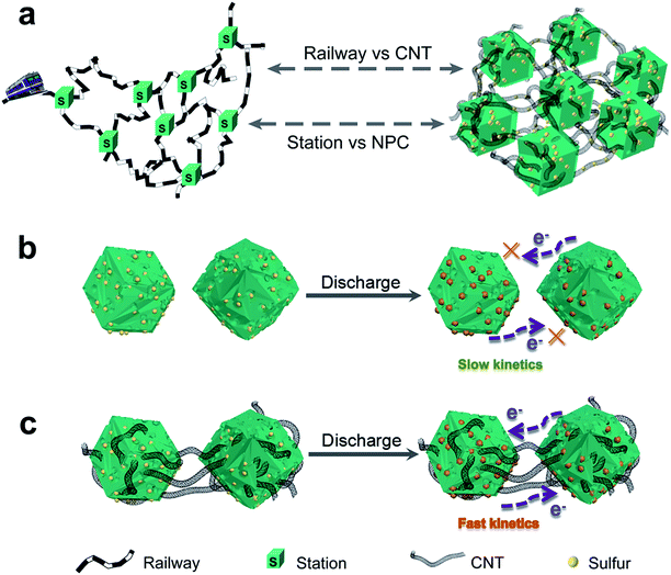 | ||
| Fig. 1 Schematic (a) of the railway-like S@CNT/NPC electrode design and (b and c) the advantages of S@CNT/NPC composite over S@NPC composite during cycling. | ||
Results and discussion
The synthetic route of S@CNT/NPC railway-like electrode is illustrated in Fig. S1.† First, carboxyl (–COOH) functional groups were introduced to the surface of CNTs by acid treatment. Then, ZIF-8 dodecahedral polyhedrons were uniformly nucleated onto the surface of CNTs and gradually grew to wrap CNTs to form CNT/ZIF-8 precursor. A uniform morphology of ZIF-8 with a size of about 1.2 μm is shown in Fig. S2.† Fig. S3† shows the dodecahedral polyhedrons shape of ZIF-8 with the distinct rhomboid face, and precursors with different amounts of CNTs are also shown in Fig. S4.† Subsequently, the CNT/ZIF-8 was chemically converted into carbon nanotubes/N-doped porous carbon polyhedrons (CNT/NPC) hybrids by an annealing treatment. The sample was then washed with 6 M HCl to remove the remaining metal Zn to form a pure porous hybrid as a carrier for S. Finally, by co-heating S and CNT/NPC in an Ar atmosphere, the S powder was melted and infiltrated into the pores to obtain S@carbon nanotubes/nitrogen-doped porous carbon (S@CNT/NPC).FESEM and TEM images are shown in Fig. 2, which indicate the unique interconnected structure of CNT/ZIF-8 and CNT/NPC precursor, such as railways and stations. The lengths of the CNTs are about 10–20 μm, and the ZIF-8 polyhedrons in series with carbon nanotubes also have an average size of about 1.2 μm. It is worth mentioning that the structure and morphology of polyhedrons remained almost intact after carbonization in a tube furnace. The nitrogen-doped porous carbon (NPC) maintained its polyhedron morphology in Fig. 2e and f. The inserting CNTs in NPC provided faster conduction pathways for electrons and Na+. Fig. 2c and g shows TEM images of CNT/ZIF-8 and CNT/NPC, we can see CNTs extending from the polyhedron, which is consistent with the FESEM observations. TGA shows that the CNTs content is about 8 wt% (Fig. S5†).
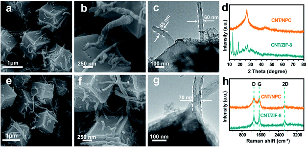 | ||
| Fig. 2 FESEM and TEM images of (a–c) CNT/ZIF-8 and (e–g) CNT/NPC. XRD and Raman spectrum patterns (d, h) of CNT/ZIF-8 and CNT/NPC. | ||
Fig. 2d shows the XRD patterns of CNT/ZIF-8 and CNT/NPC composite. The intensity of the peaks in the Fig. 2d shows that CNT/ZIF-8 has high crystallinity, and the peak around 26.5° could be due to the (002) plane of the CNTs (Fig. S6†). The powder XRD patterns of CNT/NPC exhibited two peaks at 2θ = 26° and 44°, corresponding to the (002) and (101) planes of graphite.29 In addition to D band (1320 cm−1) and G band (1549 cm−1) in Raman spectroscopy (Fig. 2h), the sample also showed a 2D peak at 2667 cm−1, which means a high graphitization degree of CNT/NPC.30 The D band is known as the defect induced peak, while the G band is the bond extension of sp2 atoms in the rings and chains. The intensity ratio of D to G peak (ID/IG) can provide references for quantification of disorder and graphitization in carbon materials.16 The ID/IG ratio of CNT/NPC was calculated to be approximately 0.98, which indicated that CNT/NPC structure had graphitic and disordered structures.
S@CNT/NPC was obtained by impregnating S into CNT/NPC hybrid at 155 °C by a typical melt diffusion process. In the XRD pattern of S@CNT/NPC, the strong peaks from orthorhombic S (JCPDS no. 08-0247) indicate that S successfully penetrated into the composite (Fig. 3e). Fig. 3a–d illustrate the distinctive hexagonal structure of the S@CNT/NPC, indicating that the structure was stable after inserting S into pores.9 Fig. S7† indicates the energy dispersive X-ray spectroscopy (EDS) mapping, and there was a homogeneous dispersion of C, S, and N throughout the sample. In Fig. 3f, the peaks at about 150 cm−1, 200 cm−1, and 500 cm−1 clearly correspond to the characteristic peaks of pure S (Fig. S8†). The TGA curve indicates that the S content in S@CNT/NPC composite was about 35 wt% in Fig. S9.†31,32
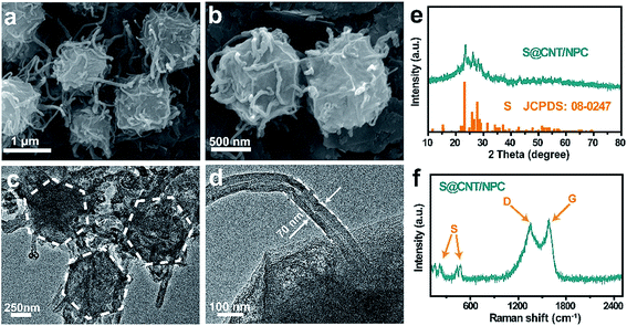 | ||
| Fig. 3 FESEM and TEM images (a–d) of S@CNT/NPC composite. XRD and Raman spectrum patterns (e and f) of S@CNT/NPC composite. | ||
The chemical valence and composition of the CNT/NPC composite were further studied by X-ray photoelectron spectroscopy (XPS). The sum XPS can be seen in Fig. S10.†Fig. 4a and b shows the detailed high resolution C 1s and N 1s XPS peaks after deconvolution. The peaks in C 1s spectrum at 284.6 eV, 285.8 eV, and 288.6 eV correspond to C–C, C![[double bond, length as m-dash]](https://www.rsc.org/images/entities/char_e001.gif) N, and C
N, and C![[double bond, length as m-dash]](https://www.rsc.org/images/entities/char_e001.gif) O (Fig. 4a).13 In addition, three peaks at 398.3 eV, 399.8 eV, and 401.1 eV in the N 1s spectrum can be ascribed to pyridinic-N, pyrrolic-N, and quaternary-N (Fig. 4b).33 The nitrogen content can be detected as 7.55 at% (Fig. S10†). Since the nitrogen-doped compounds can adsorb polysulfides in Li–S batteries,26 and it may play a similar role in room temperature Na–S batteries. The XPS test was performed on the S@CNT/NPC composite after battery cycle, and it was found that Na was present in the composite, and the position of the nitrogen element slightly shifted (Fig. S11†).
O (Fig. 4a).13 In addition, three peaks at 398.3 eV, 399.8 eV, and 401.1 eV in the N 1s spectrum can be ascribed to pyridinic-N, pyrrolic-N, and quaternary-N (Fig. 4b).33 The nitrogen content can be detected as 7.55 at% (Fig. S10†). Since the nitrogen-doped compounds can adsorb polysulfides in Li–S batteries,26 and it may play a similar role in room temperature Na–S batteries. The XPS test was performed on the S@CNT/NPC composite after battery cycle, and it was found that Na was present in the composite, and the position of the nitrogen element slightly shifted (Fig. S11†).
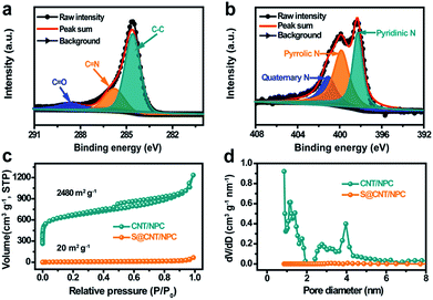 | ||
| Fig. 4 XPS spectrum of C 1s (a) and N 1s (b) of the CNT/NPC composite. Adsorption–desorption isotherms (c) and pore size distributions (d) of the CNT/NPC and S@CNT/NPC composite. | ||
In order to explore the pore size of the composite, the nitrogen adsorption/desorption isotherm was tested at 77 K. Relative BET date of CNT/ZIF-8 precursor can be seen in Fig. S12.† The CNT/NPC (Fig. 4c) exhibited high surface area of approximately 2480 m2 g−1 with a pore volume of 1.011 cm3 g−1. There was obvious adsorption in the low pressure region and a hysteresis curve in the medium pressure and high pressure regions, which indicates that the CNT/NPC composite had both micropores and mesopores.29 Similarly, we tested the specific surface area and pore volume of the NPC sample without CNTs as shown in Fig. S13.† After the infiltration of S, the BET surface area and pore volume of S@CNT/NPC were obviously reduced to 20 m2 g−1 and 0.101 cm3 g−1, respectively, which indicated that the pores within the CNT/NPC were filled with S (Fig. S14†). The uniform dispersion of S in porous carbon matrix was able to improve the charge transfer dynamics and ensured the high utilization of S. This railway-like design consisting of CNTs and tandem polyhedrons improves the electron transfer kinetics and the electrolyte infiltration.
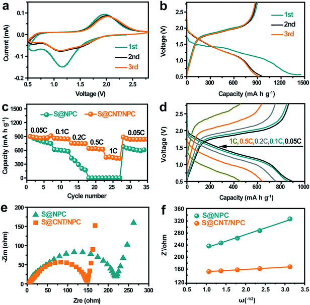
Next, we evaluated the electrochemical performance of the S@CNT/NPC composite as a cathode material for room temperature Na–S battery. Fig. 5a shows cyclic voltammograms of the cell using a scan rate of 0.1 mV s−1, one reduction peak (∼1.2 V) and one oxidation peak (∼1.8 V) are observed in the first cycle, which is in consistent with the discharge–charge curve in a constant current density of 0.05C in Fig. 5b. The initial capacity loss is attributed to the formation of solid electrolyte interphase (SEI) layer on the surface of S@CNT/NPC and the irreversible reaction between polysulfides and the carbonate solvent.14,16 After the second cycle, a stable SEI film was formed, thus the capacity tends to be stable, and the discharge curves and CV curves tend to coincide.
Fig. 5c is the rate performance of S@CNT/NPC and S@NPC composites at different current densities from 0.05C to 1C (1C = 1675 mA g−1). The S@CNT/NPC cathode delivered high capacities of 915 mA h g−1, 866 mA h g−1, 756 mA h g−1, 640 mA h g−1, and 454 mA h g−1 at 0.05C, 0.1C, 0.2C, 0.5C, and 1C, respectively. The excellent electrochemical properties originate from high conductivity of CNTs and fast reaction kinetics of the railway-like structure. After high-rate cycling, the reversible capacity could restore to 885 mA h g−1 when the current density was restored to 0.05C, indicating that the S@CNT/NPC composite had a good stability, which is much higher than that of the S@NPC composite (Fig. 5c). In addition, the capacity slightly decreased with the increase in S content in the S@CNT/NPC composite (Fig. S15†).
To further prove the conductivity of CNT, we performed impedance tests on the new static batteries of S@CNT/NPC and S@NPC, and the results are shown in Fig. 5e. The semicircle of the S@CNT/NPC electrode is smaller and the line is more inclined indicating that the S@CNT/NPC electrode had a lower charge transfer resistance and better Na+ diffusion efficiency.27 Besides, the diffusion coefficients of Na+ (DNa+) in the S@CNT/NPC and S@NPC can be calculated by the following equation:
 | (1) |
In this equation, R, T, n, F, A, and C correspond to gas constant, absolute temperature, the number of electrons transferred per mole during oxidation, Faraday constant, effective area of electrode, and Na+ concentration in cathode material, respectively. Besides, the relationship between the Warburg coefficient σw and Z′ is shown as follows:
| Z′ = R + σwω−1/2 | (2) |
R is a resistance parameter representing the combination of solution resistance and charge transfer resistance. From the slope values of Z′ and ω−1/2 (Fig. 5e) as well as eqn (1) and (2), it could be concluded that DNa+ of the S@CNT/NPC was significantly higher than that of the S@NPC. These findings indicate that CNTs have an imperative role on Na+ diffusion just like railways that is easy to transport and further attests the rational design of this S@CNT/NPC electrode structure. Besides, the S@CNT/NPC composite electrode Nyquist plots before and after cycling at 0.5C were tested and displayed in Fig. S16.† Our electrode only shows slight increase in Rct in the first few cycles.
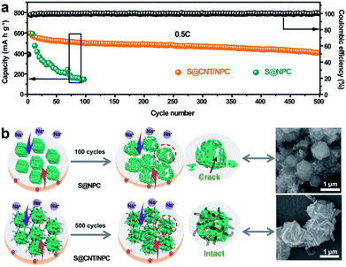
Fig. 6a shows the cycling capacity of the S@CNT/NPC composite electrode at 0.5C. The discharge capacity of 601 mA h g−1 was obtained in the third cycle. More importantly, a specific capacity of 410 mA h g−1 could be maintained after 500 cycles, with a low decline rate of 0.064% per cycle. Fig. S17† shows that the CNT/NPC network framework had no contribution to the capacity. The long cycle stability of the S@CNT/NPC cathode was due to CNTs that could connect broken parts of the polyhedrons to keep the electrode structure intact during cycles. Furthermore, the high coulombic efficiency was higher than 99% during the whole cycle, which further demonstrates that the railway-like carbon matrix host significantly increases the reaction kinetics.
In order to prove the superiority of the railway-like structure, we also conducted a comparative test. Electrochemical testing of nitrogen-doped porous carbon without CNTs in the same S content (Fig. S18†) was made. From Fig. 6a, it is clear that the capacity of S@NPC rapidly attenuated due to the unstable structure. In Fig. 6b, we can find that most S@NPC polyhedrons were broken after cycle. Conversely, the morphology and structure of the S@CNT/NPC composite could be well retained after 500 cycles (Fig. S19†). The outstanding rate capacity and stable cycle performance show that the railway-like network structure of S@CNT/NPC is suitable for room temperature Na–S battery. Moreover, we compared the performance of other electrodes in room temperature Na–S battery as in Fig. S20.† This railway-like electrode obtained a low capacity fading of 0.064% per cycle, which is superior to that of many other electrodes in references.
Experimental
Pretreatment of CNTs
0.5 g pristine multi-walled carbon nanotubes were dispersed in a mixed solution of 80 mL of concentrated sulfuric acid (H2SO4) and concentrated nitric acid (HNO3) in a volume ratio of 3![[thin space (1/6-em)]](https://www.rsc.org/images/entities/char_2009.gif) :
:![[thin space (1/6-em)]](https://www.rsc.org/images/entities/char_2009.gif) 1 in a beaker and were stirred at room temperature for 20 minutes. Next, 1.5 g of KMnO4 was slowly added to the beaker with slight stirring for 3 h at 35 °C. Finally, the mixed solution was diluted with deionized water, and then 10 mL 30% H2O2 was added dropwise. The obtained product was centrifuged, washed several times with deionized water, and dried to give the product.
1 in a beaker and were stirred at room temperature for 20 minutes. Next, 1.5 g of KMnO4 was slowly added to the beaker with slight stirring for 3 h at 35 °C. Finally, the mixed solution was diluted with deionized water, and then 10 mL 30% H2O2 was added dropwise. The obtained product was centrifuged, washed several times with deionized water, and dried to give the product.
Preparation of the CNT/ZIF-8, CNT/NPC, and S@CNT/NPC composite
![[thin space (1/6-em)]](https://www.rsc.org/images/entities/char_2009.gif) :
:![[thin space (1/6-em)]](https://www.rsc.org/images/entities/char_2009.gif) 3. The product mixture was then placed in a ceramic boat, and was annealed to 155 °C for 12 h to acquire the final S@CNT/NPC composite. The S@NPC could also be achieved by the same process.
3. The product mixture was then placed in a ceramic boat, and was annealed to 155 °C for 12 h to acquire the final S@CNT/NPC composite. The S@NPC could also be achieved by the same process.
Characterization of materials
The morphologies and structures were examined using field emission scanning electron microscope (FESEM, JSM-7800F, Japan) and transmission electrons microscopy (TEM, JEM-2100, Japan). The elemental composition and distribution of the product was investigated using energy dispersive spectroscopy (EDS, JEOL-6300F). The crystal structure and substance composition were investigated by X-ray Diffraction (XRD, MAXima-X XRD-7000). Raman spectra were measured by LabRAM HR Evolution (Horiba) Raman microscope, and the excitation laser was 532 nm. The S content in the composite was estimated using thermogravimetric analysis (TGA, Q50, USA) under nitrogen (N2) conditions. X-ray photoelectron spectroscopy (XPS) was used to measure the valence states of the elements. The measurements were performed using Thermo Scientific ESCALAB 250Xi electron spectrometer. The pore structure of the composite was characterized by Brunauer–Emmett–Teller method (BET, Quantachrome Instruments, USA).Electrochemical measurements
The active material (S@CNT/NPC), acetylene black (AB), and polyvinylidene fluoride (PVDF) binder were mixed in a ratio of 70![[thin space (1/6-em)]](https://www.rsc.org/images/entities/char_2009.gif) :
:![[thin space (1/6-em)]](https://www.rsc.org/images/entities/char_2009.gif) 20
20![[thin space (1/6-em)]](https://www.rsc.org/images/entities/char_2009.gif) :
:![[thin space (1/6-em)]](https://www.rsc.org/images/entities/char_2009.gif) 10 in N-methyl-2-pyrrolidone (NMP) and were uniformly ground and coated on smooth aluminum foils to produce working electrodes. The electrodes were then placed in an oven at 60 °C overnight for drying. In order to test the performance of room temperature Na–S batteries, we assembled the above electrodes into CR2032 batteries. The metal sodium block was pressed into sheets as counter electrodes, and the glass fibers were used as separators, and 1 M NaClO4 was dissolved in an EC
10 in N-methyl-2-pyrrolidone (NMP) and were uniformly ground and coated on smooth aluminum foils to produce working electrodes. The electrodes were then placed in an oven at 60 °C overnight for drying. In order to test the performance of room temperature Na–S batteries, we assembled the above electrodes into CR2032 batteries. The metal sodium block was pressed into sheets as counter electrodes, and the glass fibers were used as separators, and 1 M NaClO4 was dissolved in an EC![[thin space (1/6-em)]](https://www.rsc.org/images/entities/char_2009.gif) :
:![[thin space (1/6-em)]](https://www.rsc.org/images/entities/char_2009.gif) DEC in a volume ratio of 1
DEC in a volume ratio of 1![[thin space (1/6-em)]](https://www.rsc.org/images/entities/char_2009.gif) :
:![[thin space (1/6-em)]](https://www.rsc.org/images/entities/char_2009.gif) 1 as the electrolyte, and the batteries were assembled in a argon-filled glove box. The assembled batteries were allowed to stand for 8 hours to make sure the electrolyte completely wet the membrane. The battery was tested at a constant current charge and discharge of 0.5 to 2.8 V (vs. Na/Na+) at different current densities on a Land cycler (Wuhan Kingnuo Electronic Co., China). Cyclic voltammetry (CV) was performed at a scan rate of 0.1 mV s−1 using a CHI 660c electrochemical workstation (Shanghai Chenhua, China). The values of all specific capacities were calculated from the mass of active substance S. Electrochemical impedance spectroscopy (EIS) test was performed using a Zahner electrochemical workstation.
1 as the electrolyte, and the batteries were assembled in a argon-filled glove box. The assembled batteries were allowed to stand for 8 hours to make sure the electrolyte completely wet the membrane. The battery was tested at a constant current charge and discharge of 0.5 to 2.8 V (vs. Na/Na+) at different current densities on a Land cycler (Wuhan Kingnuo Electronic Co., China). Cyclic voltammetry (CV) was performed at a scan rate of 0.1 mV s−1 using a CHI 660c electrochemical workstation (Shanghai Chenhua, China). The values of all specific capacities were calculated from the mass of active substance S. Electrochemical impedance spectroscopy (EIS) test was performed using a Zahner electrochemical workstation.
Conclusions
In the study, we aimed at the problems of poor conductivity of S and volume expansion in room temperature Na–S batteries. We have designed and fabricated 3D railway-like electrodes for room temperature Na–S battery. The railway-like conductive network not only have electrons and smooth Na+ pathways to improve the redox kinetics but also have large free space for storing S species and stabilized the electrode structure by connecting polyhedrons tightly. Finally, the S@CNT/NPC composite cathode provided stable cycle life and high rate capacity due to its composition and structural advantages.Conflicts of interest
There are no conflicts to declare.Acknowledgements
This work is financially supported by grants from the National Natural Science Foundation of China (No. 21773188), Fundamental Research Funds for the Central Universities (XDJK2017A002, XDJK2017B048), Program for Innovation Team Building at Institutions of Higher Education in Chongqing (CXTDX201601011), and Graduate scientific research innovation project of Chongqing (CYB18092).References
- G. Huang, F. F. Zhang, X. C. Du, Y. L. Qin, D. M. Yin and L. M. Wang, ACS Nano, 2015, 9, 1592–1599 CrossRef CAS PubMed.
- J. T. Hu, W. Li, Y. D. Duan, S. H. Cui, X. H. Song, Y. D. Liu, J. X. Zheng, Y. Lin and F. Pan, Adv. Energy Mater., 2017, 7, 1601894 CrossRef.
- X. Q. Zhang, X. N. Li, J. W. Liang, Y. C. Zhu and Y. T. Qian, Small, 2016, 12, 2484–2491 CrossRef CAS PubMed.
- B. Chen, H. H. Lu, J. W. Zhou, C. Ye, C. S. Shi, N. Q. Zhao and S. Z. Qiao, Adv. Energy Mater., 2018, 8, 1702909 CrossRef.
- L. Wang, Z. X. Wei, M. L. Mao, H. X. Wang, Y. T. Li and J. M. Ma, Energy Storage Mater., 2019, 16, 434–454 CrossRef.
- X. L. Fan, J. Yue, F. D. Han, J. Chen, T. Deng, X. Q. Zhou, S. Y. Hou and C. S. Wang, ACS Nano, 2018, 12, 3360–3368 CrossRef CAS PubMed.
- T. Chen, Z. W. Zhang, B. R. Cheng, R. P. Chen, Y. Hu, L. B. Ma, G. Y. Zhu, J. Liu and Z. Jin, J. Am. Chem. Soc., 2017, 139, 12710–12715 CrossRef CAS PubMed.
- C. L. Dai, L. Y. Hu, M. Q. Wang, Y. M. Chen, J. Han, J. Jiang, Y. Zhang, B. L Shen, Y. B. Niu, S. J. Bao and M. W. Xu, Energy Storage Mater., 2017, 8, 202–208 CrossRef.
- S. Y. Wei, S. M. Xu, A. Agrawral, S. Choudhury, Y. Y. Lu, Z. Y. Tu, L. Ma and L. A. Archer, Nat. Commun., 2016, 6, 11722 CrossRef PubMed.
- X. C. Lu, B. W. Kirby, W. Xu, G. S. Li, J. Y. Kim, J. P. Lemmon, V. L. Sprenkle and Z. G. Yang, Energy Environ. Sci., 2013, 6, 299–306 RSC.
- A. Manthiram and X. W. Yu, Small, 2015, 11, 2108–2114 CrossRef CAS PubMed.
- Y. X. Wang, B. W. Zhang, W. H. Lai, Y. F. Xu, S. L. Chou, H. K. Liu and S. X. Dou, Adv. Energy Mater., 2017, 7, 1602829 CrossRef.
- Q. Q. Lu, X. Y. Wang, J. Cao, C. Chen, K. Chen, Z. F. Zhao, Z. Q. Niu and J. Chen, Energy Storage. Mater., 2017, 8, 77–84 CrossRef.
- L. C. Zeng, Y. Yao, J. A. Shi, Y. Jiang, W. H. Li, L. Gu and Y. Yu, Energy Storage Mater., 2016, 5, 50–57 CrossRef.
- D. T. Ma, Y. L. Li, J. B. Yang, H. W. Mi, S. Luo, L. B. Deng, C. Y. Yan, M. Rauf, P. X. Zhang, X. L. Sun, X. Z. Ren, J. Q. Li and H. Zhang, Adv. Funct. Mater., 2018, 28, 1705537 CrossRef.
- R. Carter, L. Oakes, A. Douglas, N. Muralidharan, A. P. Cohn and C. L. Pint, Nano Lett., 2017, 17, 1863–1869 CrossRef CAS PubMed.
- S. I. Kim, W. I. Park, K. Y. Jung and C. S. Kim, J. Power Sources, 2016, 320, 37–42 CrossRef CAS.
- S. Wenzel, H. Metelmann, C. Raiß, A. K. Dürr, J. Janek and P. Adelhelm, J. Power Sources, 2013, 243, 758–765 CrossRef CAS.
- I. Bauer, M. Kohl, H. Althues and S. Kaskel, Chem. Commun., 2014, 50, 3208–3210 RSC.
- Z. W. Seh, J. Sun, Y. M. Sun and Y. Cui, ACS Cent. Sci., 2015, 1, 449–455 CrossRef CAS PubMed.
- M. Kohl, F. Borrmann, H. Althues and S. Kaskel, Adv. Energy Mater., 2016, 6, 1502185 CrossRef.
- D. J. Lee, J. W. Park, I. Has, Y. K. Sun, B. Scrosatiab and J. Hassoun, J. Mater. Chem. A., 2013, 1, 5256–5261 RSC.
- W. Y. Du, Q. J. Xu, R. M. Zhan, Y. Q. Zhang, Y. S. Luo and M. W. Xu, Mater. Lett., 2018, 221, 66–69 CrossRef CAS.
- Y. Hao, X. F. Li, X. L. Sun and C. L. Wang, ChemistrySelect, 2017, 2, 9425–9432 CrossRef CAS.
- S. Xin, Y. X. Yin, Y. G. Guo and L. J. Wan, Adv. Mater., 2014, 26, 1261–1265 CrossRef CAS PubMed.
- K. Chen, Z. H. Sun, R. P. Fang, Y. Shi, H. M. Cheng and F. Li, Adv. Funct. Mater., 2018, 28, 1707592 CrossRef.
- Y. Li, M. Q. Wang, Y. M. Chen, L. Y. Hu, T. Liu, S. J. Bao and M. W. Xu, Energy Storage. Mater., 2018, 10, 10–15 CrossRef.
- G. M. Zhou, D. W. Wang, F. Li, P. X. Hou, L. C. Yin, C. Liu, G. Q. Lu, I. R. Gentlec and H. M. Cheng, Energy Environ. Sci., 2012, 5, 8901–8906 RSC.
- Y. M. Chen, W. F. Liang, S. Li, F. Zou, S. M. Bhaway, Z. Qiang, M. Gao, B. D. Vogt and Y. Zhu, J. Mater. Chem. A., 2016, 4, 12471–12478 RSC.
- Y. Z. Liu, G. R. Li, Z. W. Chen and X. S. Peng, J. Mater. Chem. A., 2017, 5, 9775–9784 RSC.
- L. Zhang, B. W. Zhang, Y. H. Dou, Y. X. Wang, M. Al-Mamun, X. L. Hu and H. K. Liu, ACS Appl. Mater. Interfaces, 2018, 10, 20422–20428 CrossRef CAS.
- B. W. Zhang, T. Sheng, Y. D. Liu, Y. X. Wang, L. Zhang, W. H Lai, L. Wang, J. P. Yang, Q. F. Gu, S. L. Chou, H. K. Liu and S. X. Dou, Nat. Commun., 2018, 9, 4082 CrossRef.
- Q. J. Xu, T. Liu, Y. Li, L. Y. Hu, C. L. Dai, Y. Q. Zhang, Y. Li, D. Y. Liu and M. W. Xu, ACS Appl. Mater. Interfaces, 2017, 9, 41339–41346 CrossRef CAS PubMed.
Footnote |
| † Electronic supplementary information (ESI) available. See DOI: 10.1039/c8ta09556f |
| This journal is © The Royal Society of Chemistry 2019 |

