 Open Access Article
Creative Commons Attribution 3.0 Unported Licence
Tetrathiafulvalene–oligofluorene star-shaped systems: new semiconductor materials for fluorescent moisture indicators†‡
Katrina
Scanlan
a,
Alexander L.
Kanibolotsky
bc,
Benjamin
Breig
a,
Gordon J.
Hedley
 b and
Peter J.
Skabara
 *b
*b
aWestCHEM, Department of Pure and Applied Chemistry, University of Strathclyde, Glasgow, G1 1XL, UK
bWestCHEM, School of Chemistry, University of Glasgow, Glasgow G12 8QQ, UK. E-mail: peter.skabara@glasgow.ac.uk
cInstitute of Physical-Organic Chemistry and Coal Chemistry, 02160 Kyiv, Ukraine
First published on 18th March 2019
Abstract
A series of novel star-shaped oligofluorene–thiophene–tetrathiafulvalene systems have been synthesised, following different synthetic routes. Each system incorporates a tetrathiafulvalene redox-active centre and four oligofluorene arms, providing a two-dimensional character to the conjugated backbone. The oligomers differ in the number of fluorene units present in the arms (1 to 4) and the terminal groups at the end of each arm (H or trimethylsilyl). Half-unit oligofluorene systems possessing a 1,3-dithiole-2-one core (a known precursor to the tetrathiafulvalene centre) have been synthesised in order to compare the thermal, optical and electrochemical properties. These half-unit systems consist of a 1,3-dithiole-2-one core fused to a thiophene unit at the 3- and 4-positions. Two oligofluorene arms consisting of 1 to 4 monomer units per arm are positioned at the 4- and 6-positions of the thiophene unit, affording extended conjugation through the thiophene centre. The half-unit systems are found to be moderate emitters in solution, however, the star-shaped systems bearing the tetrathiafulvalene core exhibit inhibited fluorescence in both solution and the solid state. We have demonstrated that the emission of the tetrathiafulvalene systems can be enhanced through the oxidation of the redox-centre followed by a consecutive reaction of the strongly electrophilic tetrathiafulvalene dication with such nucleophiles as water and hydrazine. The result of these reactions leads to an increase in the photoluminescence of these systems, affording the opportunity for the tetrathiafulvalene materials to be used as photonic materials in moisture indicators.
Introduction
Tetrathiafulvalene (TTF) has gained much attention in its role as a molecular building block for electroactive organic materials since the discovery of the electrically conductive bis-1,3-dithiolium salt.1 This observation led to developments in TTF chemistry including the discovery of charge transfer complexes, notably the donor–acceptor complex employing TTF and tetracyano-p-quinodimethane (TCNQ) which demonstrated metallic conductivity.2 Further interest in organic conductors and semiconductors was focused on mixed valence (MV) state materials.3 Bis(ethylenedithio)tetrathiafulvalene (BEDT-TTF)-based MV states demonstrated multi-dimensional stacking interactions as a consequence of S⋯S non-covalent bonding, affording a record transition temperature for ambient pressure TTF-based superconductors.4 Further work surrounded the development of multi-dimensional systems that exploited intermolecular interactions.5–8 The combination of hydrogen bonding and the propensity of TTF to form conductive aggregates was used in the design of conducting nanofibres and organogels.9,10TTF-based materials have been developed for potential use within various applications including organic photovoltaic cells,11,12 cation sensors13,14 and organic field effect transistors.15–17 Increasing the conjugation in TTF-based systems contributes to forming an increasingly polarisable species which is more likely to be involved in intermolecular interactions. Increasing the conjugation is also utilised in the stabilisation of the radical cation and dication which facilitates charge transport in the material. The extension of conjugation can be achieved through the incorporation of a conjugated spacer group between the 1,3-dithiole rings or by the fusion of conjugated polymer or oligomer chains to the peripherals of the TTF unit.18–21 The latter strategy led to development of donor systems that incorporated additional electroactive units into the system within close proximity to the TTF moiety, allowing for investigations into potential hybrid activity.22 In order to better understand the electronic properties of the doped species, conjugated oligomer arms have been employed rather than their polymer analogues.23 Conjugated oligomer chains increase the number of redox states available, produce well-defined redox signatures and allow any potential hybrid electroactivity to be observed.11,21,24,25
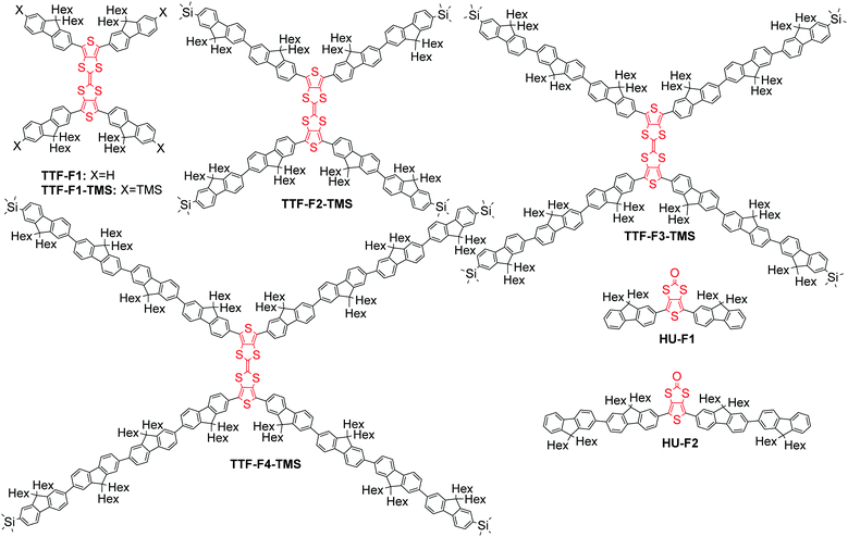
The monodisperse oligomer approach has been applied in the design of highly fluorescent star-shaped and dendritic systems.25 Star-shaped oligofluorenes demonstrated excellent film-forming properties and high photoluminescence quantum efficiencies close or better than those of linear polyfluorenes,26 which made them promising materials for applications in OLEDs,27 organic lasers28,29 and solid state down-converters.30,31 The multidimensional architecture of these macromolecular systems provides a unique stability of both p- and n-doped states with possible applications in electrogenerated chemiluminescence (ECL).32,33 Incorporating electroactive units within the arms of the star-shaped molecule34 creates the potential for multi-electron redox properties, with the radical-ion located on each branch of the doped conjugated system, which can be used for the design of efficient emitters for ECL.33 Herein, we highlight another strategy for the design of electroactive star-shaped oligofluorenes, where the TTF redox unit is positioned in the centre of the macromolecular conjugated system. The novel hybrid TTF–oligofluorene systems TTF-Fn-X (n = 1–4, X = H or trimethylsilyl) feature a 2,2′-bithieno[3,4-d][1,3]dithiolylidene core linked to four oligofluorene arms (Fig. 1). The structures differ by the length of the oligofluorene arms (mono-, bi-, ter- or quater-) or by the terminal group functionality (H or trimethylsilyl (TMS)). Oligofluorenes bearing a thieno[3,4-d][1,3]dithiol-2-one central unit HU-Fn (n = 1–2) have also been synthesised and characterised in order to compare the differences in thermal, optical and electrochemical properties. The synthetic routes to the new materials are detailed and their electronic, photophysical and thermal properties have been probed in order to determine their suitability as moisture sensors.
Results and discussion
Synthesis
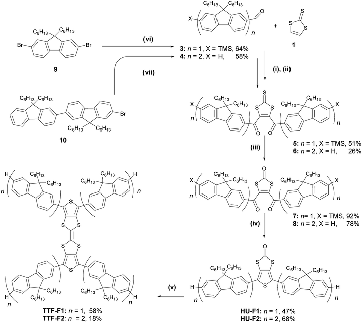
Two synthetic strategies were used in the synthesis of the TTF–oligofluorene systems, both employing a convergent approach. One strategy involves the synthesis of the TTF core using 1,3-dithiole-2-one 1 as a building block (Scheme 1), and in the other method perbromo-2,2′-bithieno[3,4-d][1,3]dithiolylidene 2 is used as a starting material (Scheme 2). The latter method was a more efficient strategy as it provided a faster route to target systems TTF-Fn-X with fewer synthetic steps and higher yields.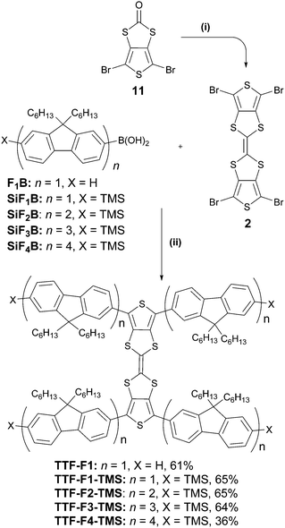 | ||
| Scheme 2 Formation of the TTF–oligofluorene systems TTF-Fn-X. Reagents and conditions: (i) P(OEt)3, 125 °C, 2 h; (ii) Pd(PPh3)4, Ba(OH)2·8H2O, H2O, THF, 140 °C, 2 h. | ||
The strategy that employed 1,3-dithiole-2-one 1 was based on a previously published procedure24,35 and employed a two-fold sequential lithiation of vinylene trithiocarbonate (VTC) 1 using LDA·THF, followed by the nucleophilic attack of lithium organic intermediates on mono- or bifluorene carbaldehydes 3–4. The intermediate unstable diols were immediately oxidised using MnO2, forming the 1,3-dithiole-2-thione diketo compounds 5–6. The oxo-derivatives of these compounds were obtained through a transchalcogenation reaction with Hg(OAc)2 conducted at room temperature, affording compounds 7–8. Compounds HU-Fn (n = 1–2) were prepared via reductive Paal–Knorr thiophene synthesis using P2S5 as the reagent. Even in the presence of NaHCO3, the reaction condition was too acidic for preserving the trimethylsilyl substituents in the case of the conversion of compound 7, and as a result the desilylated product HU-F1 was obtained. A homocoupling reaction using freshly distilled P(OEt)3 afforded TTF-F1 and TTF-F2 in yields of 58% and 18%, respectively.
Aldehyde 3 was prepared by a lithiation–trimethylsilylation–lithiation–formylation sequence using 2,7-dibromo-9,9-dihexyl-9H-fluorene 9 as a starting material (Scheme 1). Compound 4 was prepared through the lithium–halogen exchange reaction of bromobifluorene 1026 with n-BuLi followed by the addition of dimethylformamide (DMF) as an electrophile. The preparation of 3–4 afforded yields of 64% and 58%, respectively.
The convergent strategy for the synthesis of the TTF-Fn-X (n = 1–4) series employing the Suzuki coupling protocol is presented in Scheme 2. Perbromo-2,2′-bithieno[3,4-d][1,3]dithiolylidene 2 was used as a starting material and can be prepared in good yield through a homocoupling reaction of 11 with triethyl phosphite.19TTF-F1 was prepared through the Suzuki coupling of 2 to fluorenyl boronic acid F1B in a microwave-assisted reaction. Barium hydroxide was employed in excess as a strong base to encourage an efficient coupling. The temperature of the reaction was raised step-wise above the boiling point of THF to promote the four-fold coupling of the oligofluorenyl boronic acid. The same synthetic approach was used to obtain TTF-Fn-TMS (n = 1–4) employing the same reaction conditions and using the corresponding oligofluorenyl boronic acids SiF1B–SiF4B. The yields for the TTF-Fn-X series using this method are all within 64–65%, with the exception of TTF-F4-TMS (yield 36%).
The synthetic route to the fluorenyl boronic acid F1B and trimethylsilyl boronic acids SiF1B–SiF3B has previously been described in the literature.34
Physical characterisation
| Compound | M W (g mol−1) | T g (°C) | T d (5% mass loss) (°C) |
|---|---|---|---|
| HU-F1 | 839.31 | 25 | 374 |
| HU-F2 | 1504.37 | 61 | 410 |
| TTF-F1 | 1646.63 | 65 | 377 |
| TTF-F1-TMS | 1935.35 | — | 385 |
| TTF-F2-TMS | 3265.48 | 83 | 411 |
| TTF-F3-TMS | 4595.60 | 91 | 425 |
| TTF-F4-TMS | 5925.73 | 96 | 417 |
In differential scanning calorimetry (DSC) experiments (Fig. S2, ESI‡), a glass transition temperature is observed for all compounds apart from the trimethylsilyl substituted monofluorene–TTF system TTF-F1-TMS. All TTF-core star-shaped systems are amorphous materials with glass transition temperatures in the range of 25–96 °C. The bifluorene unit containing the 1,3-dithiole-2-one core HU-F2 and its TTF analogue TTF-F2-TMS also possess a crystallisation and melting point in addition to the observed glass transition temperature. Compound HU-F1 has the lowest glass transition temperature at 25 °C, while the largest system in the series TTF-F4-TMS has the highest glass transition at 96 °C. Similar trends have been observed in the T1–T4 truxene–oligofluorene systems,26,28 in which glass transition temperatures increase with higher molecular weight.
| Compound |
E
pox
![[thin space (1/6-em)]](https://www.rsc.org/images/entities/char_2009.gif) (V)
(V) |
HOMOb (eV) | E pred (V) | LUMOb (eV) |
E
ECg
![[thin space (1/6-em)]](https://www.rsc.org/images/entities/char_2009.gif) (eV)
(eV) |
E
optg
![[thin space (1/6-em)]](https://www.rsc.org/images/entities/char_2009.gif) (eV) [λonset (nm)]
(eV) [λonset (nm)] |
|---|---|---|---|---|---|---|
| a The positions of peaks on the forward/reverse scan vs. the Fc/Fc+ redox couple are given for reversible or quasi-reversible waves; for irreversible processes the peaks on a forward scan are presented. b The electrochemical HOMO (LUMO) level was calculated using the half-wave potential of the first oxidation wave or the onset of the first irreversible reduction wave, taking into account that the HOMO of Fc is 4.8 eV. c The optical HOMO–LUMO gap (Eg) has been estimated using the formula Eg = 1239.84/λonset from absorption onset (λonset) shown in brackets (in nm). d The electrochemical HOMO–LUMO gap is estimated from the energy difference between the LUMO and HOMO levels. | ||||||
| HU-F1 | +0.78/+0.52, +1.11, +1.89 | −5.45 | — | −2.48 | 2.97 | 2.88 (430) |
| HU-F2 | +0.77/+0.72, +0.93/+0.88, +1.19/+1.12, +1.48/1.34 | −5.55 | −2.35 | −2.58 | 2.97 | 2.66 (466) |
| −2.48 | ||||||
| TTF-F1 | +0.39/+0.21, +0.82/+0.69, +1.14/+1.04, +1.28 | −5.1 | — | −2.33 | 2.77 | 2.84 (436) |
| TTF-F1-TMS | +0.44/+0.24, +0.89/+0.74, +1.18/+1.08, +1.27, +1.36, +1.47 | −5.14 | — | −2.42 | 2.72 | 2.81 (442) |
| TTF-F2-TMS | +0.41/+0.23, +0.87/+0.80, +1.19/+1.02, +1.36/+1.21 | −5.12 | — | −2.53 | 2.59 | 2.72 (455) |
| TTF-F3-TMS | +0.57/+0.35, +0.93/+0.85, +1.17/+1.07, +1.54/+1.43, +1.64/1.55 | −5.26 | — | −2.57 | 2.69 | 2.72 (456) |
| TTF-F4-TMS | +0.61/+0.28, +0.84/+0.77, +0.99/+0.92, +1.31/+1.17, +1.49/+1.36, +1.59/+1.43 | −5.25 | — | −2.59 | 2.66 | 2.71 (457) |
In contrast, it was observed that in systems with more than one fluorene unit per oligomer arm (TTF-F2-TMS–TTF-F4-TMS) only the first wave related to the oxidation of the TTF core was resolved; the second oxidation overlapped with the reversible two-electron wave corresponding to the oxidation of 2,5-bis(oligofluorene)thiophene conjugated units. As the lengths of the arms increased, more reversible and quasi-reversible oxidation waves were observed, demonstrating an improved stability towards p-doping in the system with longer conjugation paths. The anodic/cathodic peaks of the oxidation waves are presented in Table 2, with the voltammograms shown in Fig. S3 (ESI‡).
The systems featuring the thieno[3,4-d][1,3]dithiol-2-one core flanked with mono- and bifluorene arms, HU-F1 and HU-F2, respectively, reveal a higher oxidation onset of around +0.7 V. The CV of HU-F1 shows one quasi-reversible wave at a half-wave potential of +0.65 V and two irreversible waves with peak potentials at +1.11 V and +1.89 V; HU-F2 exhibits three reversible oxidation waves at half-wave potentials of +0.74 V, +0.90 V and +1.15 V. The oxidation of compound HU-F2 is observed to be more reversible in comparison to HU-F1 as a consequence of its extended conjugation. The oligomer HU-F2 was the only oligofluorene to exhibit two irreversible waves at −2.35 V and −2.48 V. For all other compounds only the reduction onsets were observed.
The electrochemical HOMO–LUMO gap values for the systems containing the thieno[3,4-d][1,3]dithiol-2-one moiety HU-F1 and HU-F2 were estimated to both be 2.97 eV, ca. 0.09–0.31 eV higher than the corresponding optical HOMO–LUMO gap. In contrast, the TTF-cored star shaped systems were found to have HOMO–LUMO gap values within the range of 2.59–2.77 eV, which are lower than the corresponding optical HOMO–LUMO gap values by 0.03–0.13 eV due to the HOMO residing on the TTF central unit and not on the fluorene–thiophene conjugated segments.
Optical properties
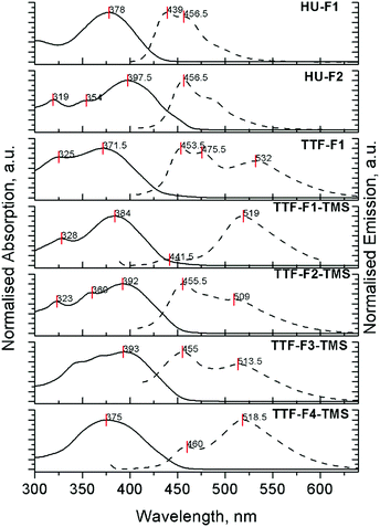
The absorption and emission properties of compounds HU-Fn and the TTF-Fn-X series in dichloromethane were investigated (Tables 3, 4 and Fig. S4, S5, ESI‡). Compounds TTF-F1 and TTF-F1-TMS reveal main absorption bands with peak maxima at 372 nm and 384 nm, respectively (Fig. 2). These intense absorption peaks are attributed to the π–π* transition occurring on the fluorene–thiophene–fluorene units, by analogy with the half-units HU-Fn. The main absorption peaks in the spectra of compounds TTF-F2-TMS and TTF-F3-TMS positioned at 392 nm and 396 nm, respectively, are attributed to the π–π* transition occurring on the bifluorene–thiophene–bifluorene units. It is suggested that the absorption of the 2,2′-bithieno[3,4-d][1,3]dithiolylidene (DT-TTF) core may contribute to the higher energy features around 320 nm in the absorption spectra of TTF-F1 and TTF-Fn-TMS (n = 1–2).40 Compound TTF-F2-TMS reveals an additional higher energy band at 360 nm. The extent of the conjugation which controls the main absorption band is limited to the bifluorene units on either side of the thiophene moiety; as the length of oligofluorene arms increases past this limit, the absorption of the oligofluorene arms contributes more to the spectra. This can be observed by the broadening of the absorption band and the overlapping of peaks in the spectrum of TTF-F3-TMS and, additionally, by a featureless absorption band at 375 nm in the spectrum of compound TTF-F4-TMS. The hypsochromic shift of the peak maximum shows that the oligofluorene units dominated absorption as the oligofluorene chain length increased. The position of the peak maximum is similar to that observed in the absorption spectrum of quaterfluorene molecules in dichloromethane.41,42 By comparison, the monofluorene system containing the 1,3-dithiol-2-one unit HU-F1 reveals a peak maximum at 378 nm, similar to its TTF-F1 analogue and consistent with absorption of the thieno[3,4-d][1,3]dithiol-2-one core extending over the fluorenyl arms. The bifluorene analogue HU-F2 reveals a peak maximum red-shifted by 21 nm (λmax = 399 nm), when compared to HU-F1 denoting the effects of extended conjugation. Compounds HU-F2 and TTF-F2-TMS have similar absorption profiles, with the positions of the bands not changing significantly.| Compound | Peak maximum (nm) [log![[thin space (1/6-em)]](https://www.rsc.org/images/entities/char_2009.gif) ε]/absorption onset (nm) ε]/absorption onset (nm) |
|---|---|
| CH2Cl2 | |
| HU-F1 | 378 (4.98)/430 |
| HU-F2 | 319 (4.99), 354 (4.98), 398 (5.21)/466 |
| TTF-F1 | 325 (5.19), 372 (5.27)/436 |
| TTF-F1-TMS | 328 (5.17), 384 (5.43)/442 |
| TTF-F2-TMS | 323 (5.54), 360 (5.65), 392 (5.73)/455 |
| TTF-F3-TMS | 394 (5.90)/456 |
| TTF-F4-TMS | 375 (5.79)/457 |
The UV-Vis absorption spectra of compounds HU-Fn and TTF-Fn-X were investigated in the concentrations range of 1 × 10⁻⁷–1 × 10⁻⁵ M and revealed no changes in the spectra.
The fluorescence spectra for compounds HU-Fn and TTF-Fn-X in dichloromethane are shown in Fig. 2, the peak maxima and photoluminescence quantum yield (PLQY) being collated in Table 4. All the TTF-core star shaped systems reveal two emission bands in the regions 440–480 nm and 500–550 nm. The relative intensity of these emission bands in all TTF-bearing compounds TTF-F1 and TTF-Fn-TMS (n = 1–4) was found to depend on the concentration of solutions (Fig. S5, ESI‡). In solutions of these compounds at a low concentration of 10−7 M, the shorter wavelength band is found to dominate the emission spectra. At higher concentrations (10−5 M) the longer wave band becomes dominant. This is a result of the aggregating ability of TTF43 which at high concentrations results in red-shifted emission. Although we did not observe any changes in the absorption spectra upon changing the concentration, vide supra, as we have seen with a star-shaped tetrakis(quaterfluorene)diketopyrrolopyrrole compound,44 the aggregation does reveal itself through changes in the photoluminescence (PL) spectra. The observation of aggregation by PL has also been reported for tetraphenylethene (TPE)–oligofluorene star-shaped systems.45 Self-absorption leads to a small bathochromic shift of a few nanometres for the higher energy band in more concentrated solutions for all compounds, HU-Fn and TTF-Fn-X. In contrast to the TTF-cored oligofluorenes, compounds HU-Fn did not reveal any change in the shape of the emission profile in the range of concentrations 10−7–10−5 M.
| Compound | Peak maxima (nm) [PLQY] | |
|---|---|---|
| CH2Cl2 | Film | |
| HU-F1 | 439, 457 (<2%) | 466 (<1%) |
| HU-F2 | 457 (25.9%) | 467 (<1%) |
| TTF-F1 | 454, 476, 532 (<1%) | 488 (<1%) |
| TTF-F1-TMS | 442, 519 (<1%) | 438 (<1%) |
| TTF-F2-TMS | 455, 509 (<1%) | 437, 487 (<1%) |
| TTF-F3-TMS | 455, 514 (∼1%) | 442, 493 (<1%) |
| TTF-F4-TMS | 460, 519 (1.2–1.4%) | 437, 467 (<1%) |
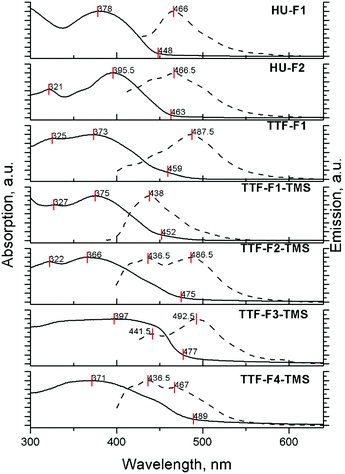
The absorption and emission properties of compounds HU-Fn and TTF-Fn-X in films drop-cast from 3 mg ml−1 solutions in toluene are shown in Fig. 3. The absorption spectra of the materials all reveal unresolved bands due to broadening which arise as a result of the higher degree of aggregation occurring in the solid state. The positions of the absorption peaks do not change significantly, however the absorption onset of these films reveals a bathochromic shift as a result of the more rigid molecular structure in the solid-state.
The emission spectra of TTF-cored star-shaped oligofluorenes TTF-Fn-X reveal band broadening and a hypsochromic shift of emission. In the solid-state, where there are extensive intermolecular interactions in the bulk, emission occurs from multiple overlapping excited states leading to a broader band being observed. The hypsochromic shift is attributed to the confinement of molecules in the solid state, leading to a hindered structural relaxation within the excited state. In contrast, the emission spectra of compounds HU-Fn in films reveal a featureless emission band with a bathochromic shift compared to the emission in solution.
The hypsochromic shift in the solid state and the dependence of the shape of the emission profile on the concentration have been observed earlier for star-shaped oligofluorenes with a tetraphenylethene (TPE) core.45
The electrochemical HOMO–LUMO gap values (Table 2) estimated for compounds bearing a TTF core TTF-F1 and TTF-Fn-TMS (n = 1–4) are in the range of 2.48–2.71 eV, showing that the gap is not significantly affected by extending the conjugation through additional fluorene units and that the TTF core is responsible for the initial oxidation of the materials. The oligofluorenes (HU-Fn), show an electrochemical HOMO–LUMO gap of 3.02 eV and 2.89 eV, respectively. These values are higher than those observed for TTF-F1-TMS and TTF-F2-TMS, showing the influence of TTF in decreasing the oxidation potential of these species. The optical HOMO–LUMO gaps for the TTF-bearing materials (TTF-F1 and TTF-Fn-TMS) are larger than the value calculated through the electrochemical method. In the determination of the HOMO–LUMO gap through electrochemical methods, the HOMO located on the TTF is not involved in the lowest π–π* transition. It has previously been suggested that as a consequence of low oscillator strength, the optical transition in the material could occur from the HOMO-1 orbital as opposed to the HOMO.11 This reasoning would account for the higher energy optical HOMO–LUMO gap observed in these materials. Compounds HU-Fn, in which the TTF core is absent have a lower optical HOMO–LUMO gap (2.88 eV and 2.66 eV, respectively), than the value obtained from electrochemical methods. This difference in value is attributed to the energy required to overcome the electron–hole pair binding energy.46
The photoluminescence quantum yields were determined from films of the materials HU-Fn and the TTF-Fn-X series and were found to be below 1% for all compounds. This quenching of emission is attributed either to the aggregation of molecules occurring within the solid state or the TTF core. The PLQY for compound HU-F2 (25.9%) in dichloromethane was significantly higher whilst TTF-bearing compounds in the solution-state exhibited PLQYs under 2%. Intramolecular photoinduced electron transfer47 might be responsible for the quenching of the oligofluorene fluorescence in these systems.
Using doped TTF core as a switch for PL emission
In order to investigate the possibility of tuning the emissive properties of the star-shaped oligofluorenes TTF-Fn-TMS in solution using the redox switchable TTF core unit, the PL spectrum of compound TTF-F3-TMS was compared before and after addition of the oxidising agent nitrosonium hexafluorophosphate. Nitrosonium hexafluorophosphate (2 equivalents) was added to compound TTF-F3-TMS in CH2Cl2 (1 × 10⁻⁶ M) and the PL spectra were measured at regular intervals. The emission spectrum of neutral compound TTF-F3-TMS revealed two bands, at 455 nm and 514 nm. On addition of the oxidant, the relative intensities of these two bands changed, with the shorter wavelength band beginning to dominate emission (Fig. 4). As time increased, the longer wavelength band disappeared, and at t = 30 min the appearance of a shoulder at ∼480 nm was observed. The intensity of the band at 455 nm continued to increase resulting in a time-dependent enhancement of emission. Hydrazine monohydrate was used as the reducing agent in an attempt to restore the neutral TTF unit. After the addition of hydrazine monohydrate, the PL intensity did not decrease but surprisingly was enhanced further, with the short wavelength emission increasing beyond the fluorimeter measurement range (Fig. S6, ESI‡). It is suggested that the irreversible increase in fluorescence of oxidised TTF-F3-TMS with time is a consequence of the strong electrophilic nature of the dication formed upon oxidation, which is susceptible to a reaction with traces of water or N2H4. In fact, the reaction involving the rearrangement of a TTF cation radical upon its reaction with water has previously been reported.48,49 In these reactions, the proposed mechanism describes a one-electron oxidation of the TTF centre affording an electrophilic cation radical which in the presence of water leads to the formation of a hydroxylic functionality on the TTF centre. An additional one-electron oxidation affords a pinacol-type rearrangement of the system by a 1,2-sulfenyl shift which leads to a ring expansion, formation of a spirocentre and, after the loss of a proton, a carbonyl unit (Fig. 5).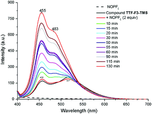 | ||
| Fig. 4 PL spectra showing the enhancement in emission of doped TTF-F3-TMS in CH2Cl2 (1.0 × 10⁻⁶ M) in the presence of water. Dopant used was NOPF6 in CH3CN (2 equiv.); λex = 396 nm. | ||
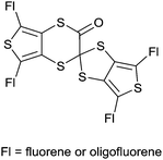 | ||
| Fig. 5 Proposed rearrangement product according to ref. 48 and 49. | ||
The reactivity of the doped TTF unit can be used to tune the emission of the star-shaped based materials using water as an external stimulus, in order to create a solution-processable fluorescent moisture indicator. As a proof of concept for the ability of the TTF–oligofluorene materials to act as fluorescent sensors to moisture, an experiment was designed in which the TTF-F3-TMS monodisperse system was incorporated into a photocurable matrix. This was achieved by encapsulating the TTF-F3-TMS compound within a photoresist in a nitrogen filled glovebox environment, thus ensuring that the system was exposed to minimal levels of moisture and oxygen and additionally ensuring that the enhancement of emission observed in prior experiments did not occur prematurely.
An ideal matrix should have minimal interference with the optical properties of the TTF-F3-TMS system for its application to be viable. As a result, the photocurable matrix was based on a previously developed negative photoresist which incorporated the cross-linking system 1,4-cyclohexyldimethanol divinyl ether (CHDV) in combination with the photoacid generator (PAG), 4-octyloxydiphenyliodonium hexafluoroantimonate.50 CHDV is devoid of aromatic groups which (i) increases the transparency of the system to UV radiation and (ii) decreases the potential of solvatochromic shifts. An increase in transparency of the photocurable system is beneficial in maximising the photoexcitation of the TTF–oligofluorene system. Additionally, reducing the chances of solvatochromic shifts ensures the spectral properties of TTF-F3-TMS are sustained. 4-Octyloxydiphenyliodonium hexafluoroantimonate is beneficial in solubilising the TTF–oligofluorene system due to the presence of its long alkyl chains. The combination of PAG and CHDV is known to require deep UV-radiation to induce photocuring (Fig. 6), affording a photoresist system which has over 90% transparency at 250 nm.50
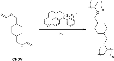 | ||
| Fig. 6 Cross-linking of the monomer CHDV by UV irradiation in the presence of a photoacid generator (PAG). | ||
The CHDV/TTF-F3-TMS photocurable matrix was achieved by using 0.1 wt% PAG and 0.1 wt% TTF-F3-TMS. Larger quantities of the PAG (>0.5 wt%) were found to cause uncontrollable polymerisation even without UV irradiation. 4-Octyloxydiphenyliodonium hexafluoroantimonate was initially dissolved in a mixture of dry solvent of dichloromethane![[thin space (1/6-em)]](https://www.rsc.org/images/entities/char_2009.gif) :
:![[thin space (1/6-em)]](https://www.rsc.org/images/entities/char_2009.gif) toluene in a 1
toluene in a 1![[thin space (1/6-em)]](https://www.rsc.org/images/entities/char_2009.gif) :
:![[thin space (1/6-em)]](https://www.rsc.org/images/entities/char_2009.gif) 1 ratio, affording better solubility of the photoinitiator in TTF-F3-TMS/CHDV solution. Due to the low viscosity of CHDV (4 cP), the method of drop-casting was used to prepare films onto a fused silica substrate.51 The matrix was cured using short wavelength UV irradiation at 254 nm.
1 ratio, affording better solubility of the photoinitiator in TTF-F3-TMS/CHDV solution. Due to the low viscosity of CHDV (4 cP), the method of drop-casting was used to prepare films onto a fused silica substrate.51 The matrix was cured using short wavelength UV irradiation at 254 nm.
The photocured CHDV/TTF-F3-TMS matrix fabricated within a glovebox environment was later exposed to water as an external stimulus, gauging the probability of the system as a fluorescent moisture indicator. Fig. 7 presents a photograph of the film before (middle) and after (right) exposing to water, along with the blank CHDV film without TTF-F3-TMS (left). The appearance of the film before and after exposure to water, the corresponding PL spectra (Fig. S7, ESI‡), as well as PLQY measurements (Table 5), prove an enhancement in fluorescence due to the presence and subsequent reaction with water and that the materials designed in this paper can be used for fluorescent moisture indicators. Since water clearly interacts with the TTF-F3-TMS in the matrix, our belief is that the PAG molecule is responsible for protonation or oxidation of the TTF core to create an electrophilic intermediate that reacts with water. Further work will be carried out to isolate the product of the rearrangement and to improve the response of the sensor towards the presence of water. The latter will include: (a) better control of the TTF–oligofluorene doping within the matrix; (b) design of a matrix that will provide better permeability for water molecules and a greater degree of freedom for TTF-F3-TMS in order to achieve a faster transformation of the TTF-core.
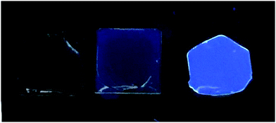 | ||
| Fig. 7 Photographs of the cured films prepared from blends: CHDV with 0.1% of PAG (left); CHDV with 0.1% of TTF-F3-TMS and 0.1% of PAG before (middle) and after exposure to water (right). | ||
| Blend composition | PLQY, % | |
|---|---|---|
| a | CHDV with 0.1% of PAG | <1% |
| b | CHDV with 0.1% of PAG and 0.1% of TTF-F3-TMS before exposure to water | 0.8–1.2 |
| c | CHDV with 0.1% of PAG and 0.1% of TTF-F3-TMS after exposure to water | 2.6–2.9 |
Summary
In conclusion, a novel series of TTF–fluorene star-shaped conjugated systems TTF-Fn-X was designed and synthesised. In contrast to other star-shaped oligofluorene systems, where we used the core unit for tuning the emission of the materials, the star-shaped oligomers described in this paper contain a TTF unit as the core structure. As expected, the fluorescent properties of the novel materials are poor both in solution and film. The TTF-cored star-shaped oligofluorenes were found to strongly aggregate in solution. While oxidised, the TTF core becomes extremely electrophilic and can react irreversibly with water to increase the PL emission of the oligofluorene arms, allowing for the newly designed star-shaped materials to be considered attractive for applications in fluorescent moisture indicators.Conflicts of interest
There are no conflicts to declare.Acknowledgements
We thank the EPSRC for funding under grants EP/P02744X/2 and EP/R03480X/1.References
- F. Wudl, D. Wobschall and E. J. Hufnagel, J. Am. Chem. Soc., 1972, 94, 670–672 CrossRef CAS.
- J. Ferraris, D. O. Cowan, V. Walatka and J. H. Perlstein, J. Am. Chem. Soc., 1973, 95, 948–949 CrossRef CAS.
- D. Jérome, Chem. Rev., 2004, 104, 5565–5592 CrossRef PubMed.
- A. M. Kini, U. Geiser, H. H. Wang, K. D. Carlson, J. M. Williams, W. K. Kwok, K. G. Vandervoort, J. E. Thompson and D. L. Stupka, Inorg. Chem., 1990, 29, 2555–2557 CrossRef CAS.
- M. R. Bryce, W. Devonport, L. M. Goldenberg and C. Wang, Chem. Commun., 1998, 945–952 RSC.
- A. Kanibolotsky, S. Roquet, M. Cariou, P. Leriche, C.-O. Turrin, R. de Bettignies, A.-M. Caminade, J.-P. Majoral, V. Khodorkovsky and A. Gorgues, Org. Lett., 2004, 6, 2109–2112 CrossRef CAS PubMed.
- Y. Morita, S. Maki, M. Ohmoto, H. Kitagawa, T. Okubo, T. Mitani and K. Nakasuji, Org. Lett., 2002, 4, 2185–2188 CrossRef CAS PubMed.
- T. Murata, Y. Morita, K. Fukui, K. Sato, D. Shiomi, T. Takui, M. Maesato, H. Yamochi, G. Saito and K. Nakasuji, Angew. Chem., Int. Ed., 2004, 43, 6343–6346 CrossRef CAS PubMed.
- X. Yang, D. Zhang, G. Zhang and D. Zhu, Sci. China: Chem., 2011, 54, 596–602 CrossRef CAS.
- S. K. M. Nalluri, N. Shivarova, A. L. Kanibolotsky, M. Zelzer, S. Gupta, P. W. J. M. Frederix, P. J. Skabara, H. Gleskova and R. V. Ulijn, Langmuir, 2014, 30, 12429–12437 CrossRef CAS PubMed.
- I. A. Wright, N. J. Findlay, S. Arumugam, A. R. Inigo, A. L. Kanibolotsky, P. Zassowski, W. Domagala and P. J. Skabara, J. Mater. Chem. C, 2014, 2, 2674–2683 RSC.
- S. Arumugam, D. Cortizo-Lacalle, S. Rossbauer, S. Hunter, A. L. Kanibolotsky, A. R. Inigo, P. A. Lane, T. D. Anthopoulos and P. J. Skabara, ACS Appl. Mater. Interfaces, 2015, 7, 27999–28005 CrossRef CAS PubMed.
- T. Jorgensen, T. K. Hansen and J. Becher, Chem. Soc. Rev., 1994, 23, 41–51 RSC.
- D. Canevet, M. Salle, G. Zhang, D. Zhang and D. Zhu, Chem. Commun., 2009, 2245–2269 RSC.
- M. Mas-Torrent, M. Durkut, P. Hadley, X. Ribas and C. Rovira, J. Am. Chem. Soc., 2004, 126, 984–985 CrossRef CAS PubMed.
- M. Mas-Torrent, P. Hadley, S. T. Bromley, N. Crivillers, J. Veciana and C. Rovira, Appl. Phys. Lett., 2005, 86, 012110 CrossRef.
- R. G. D. Taylor, J. Cameron, I. A. Wright, N. Thomson, O. Avramchenko, A. L. Kanibolotsky, A. R. Inigo, T. Tuttle and P. J. Skabara, Beilstein J. Org. Chem., 2015, 11, 1148–1154 CrossRef CAS PubMed.
- T. Sugimoto, H. Awaji, I. Sugimoto, Y. Misaki, T. Kawase, S. Yoneda, Z. Yoshida, T. Kobayashi and H. Anzai, Chem. Mater., 1989, 1, 535–547 CrossRef CAS.
- P. J. Skabara, R. Berridge, E. J. L. McInnes, D. P. West, S. J. Coles, M. B. Hursthouse and K. Mullen, J. Mater. Chem., 2004, 14, 1964–1969 RSC.
- P. Frere and P. J. Skabara, Chem. Soc. Rev., 2005, 34, 69–98 RSC.
- R. Berridge, I. M. Serebryakov, P. J. Skabara, E. Orti, R. Viruela, R. Pou-Amerigo, S. J. Coles and M. B. Hursthouse, J. Mater. Chem., 2004, 14, 2822–2830 RSC.
- R. Berridge, P. J. Skabara, C. Pozo-Gonzalo, A. Kanibolotsky, J. Lohr, J. J. W. McDouall, E. J. L. McInnes, J. Wolowska, C. Winder, N. S. Sariciftci, R. W. Harrington and W. Clegg, J. Phys. Chem. B, 2006, 110, 3140–3152 CrossRef CAS PubMed.
- A. L. Kanibolotsky, L. Kanibolotskaya, S. Gordeyev, P. J. Skabara, I. McCulloch, R. Berridge, J. E. Lohr, F. Marchioni and F. Wudl, Org. Lett., 2007, 9, 1601–1604 CrossRef CAS PubMed.
- I. A. Wright, P. J. Skabara, J. C. Forgie, A. L. Kanibolotsky, B. Gonzalez, S. J. Coles, S. Gambino and I. D. W. Samuel, J. Mater. Chem., 2011, 21, 1462–1469 RSC.
- A. L. Kanibolotsky, I. F. Perepichka and P. J. Skabara, Chem. Soc. Rev., 2010, 39, 2695–2728 RSC.
- A. L. Kanibolotsky, R. Berridge, P. J. Skabara, I. F. Perepichka, D. D. C. Bradley and M. Koeberg, J. Am. Chem. Soc., 2004, 126, 13695–13702 CrossRef CAS PubMed.
- Y. Zou, J. Zou, T. Ye, H. Li, C. Yang, H. Wu, D. Ma, J. Qin and Y. Cao, Adv. Funct. Mater., 2013, 23, 1781–1788 CrossRef CAS.
- G. Tsiminis, Y. Wang, P. E. Shaw, A. L. Kanibolotsky, I. F. Perepichka, M. D. Dawson, P. J. Skabara, G. A. Turnbull and I. D. W. Samuel, Appl. Phys. Lett., 2009, 94, 243304 CrossRef.
- Y. Wang, G. Tsiminis, Y. Yang, A. Ruseckas, A. L. Kanibolotsky, I. F. Perepichka, P. J. Skabara, G. A. Turnbull and I. D. W. Samuel, Synth. Met., 2010, 160, 1397–1400 CrossRef CAS.
- D. A. Vithanage, P. P. Manousiadis, M. T. Sajjad, S. Rajbhandari, H. Chun, C. Orofino, D. Cortizo-Lacalle, A. L. Kanibolotsky, G. Faulkner, N. J. Findlay, D. C. O'Brien, P. J. Skabara, I. D. W. Samuel and G. A. Turnbull, Appl. Phys. Lett., 2016, 109, 013302 CrossRef.
- M. T. Sajjad, P. P. Manousiadis, C. Orofino, A. L. Kanibolotsky, N. J. Findlay, S. Rajbhandari, D. A. Vithanage, H. Chun, G. E. Faulkner, D. C. O'Brien, P. J. Skabara, G. A. Turnbull and I. D. W. Samuel, Appl. Phys. Lett., 2017, 110, 013302 CrossRef.
- K. M. Omer, A. L. Kanibolotsky, P. J. Skabara, I. F. Perepichka and A. J. Bard, J. Phys. Chem. B, 2007, 111, 6612–6619 CrossRef CAS PubMed.
- Z. Mohsan, A. L. Kanibolotsky, A. J. Stewart, A. R. Inigo, L. Dennany and P. J. Skabara, J. Mater. Chem. C, 2015, 3, 1166–1171 RSC.
- C. R. Belton, A. L. Kanibolotsky, J. Kirkpatrick, C. Orofino, S. E. T. Elmasly, P. N. Stavrinou, P. J. Skabara and D. D. C. Bradley, Adv. Funct. Mater., 2013, 23, 2792–2804 CrossRef CAS.
- P. J. Skabara, I. M. Serebryakov, D. M. Roberts, I. F. Perepichka, S. J. Coles and M. B. Hursthouse, J. Org. Chem., 1999, 64, 6418–6424 CrossRef CAS.
- M. R. Bryce, J. Mater. Chem., 2000, 10, 589–598 RSC.
- E. Ertas, İ. Demirtas and T. Ozturk, Beilstein J. Org. Chem., 2015, 11, 403–415 CrossRef CAS PubMed.
- Y. Sun, Z. Cui, L. Chen, X. Lu, Y. Wu, H.-L. Zhang and X. Shao, RSC Adv., 2016, 6, 79978–79986 RSC.
- N. G. Connelly and W. E. Geiger, Chem. Rev., 1996, 96, 877–910 CrossRef CAS PubMed.
- C. Rovira, J. Veciana, N. Santalo, J. Tarres, J. Cirujeda, E. Molins, J. Llorca and E. Espinosa, J. Org. Chem., 1994, 59, 3307–3313 CrossRef CAS.
- R. Anemian, J.-C. Mulatier, C. Andraud, O. Stephan and J.-C. Vial, Chem. Commun., 2002, 1608–1609, 10.1039/B201414A.
- P. Robert, A. Bolduc and W. G. Skene, J. Phys. Chem. A, 2012, 116, 9305–9314 CrossRef CAS PubMed.
- M. Iyoda and M. Hasegawa, Beilstein J. Org. Chem., 2015, 11, 1596–1613 CrossRef CAS PubMed.
- A. L. Kanibolotsky, F. Vilela, J. C. Forgie, S. E. T. Elmasly, P. J. Skabara, K. Zhang, B. Tieke, J. McGurk, C. R. Belton, P. N. Stavrinou and D. D. C. Bradley, Adv. Mater., 2011, 23, 2093–2097 CrossRef CAS PubMed.
- C. Orofino, C. Foucher, F. Farrell, N. J. Findlay, B. Breig, A. L. Kanibolotsky, B. Guilhabert, F. Vilela, N. Laurand, M. D. Dawson and P. J. Skabara, J. Polym. Sci., Part A: Polym. Chem., 2017, 55, 734–746 CrossRef CAS PubMed.
- J.-L. Bredas, Mater. Horiz., 2014, 1, 17–19 RSC.
- F. Pop and N. Avarvari, Chem. Commun., 2016, 52, 7906–7927 RSC.
- W. R. H. Hurtley and S. Smiles, J. Chem. Soc., 1926, 129, 2263–2270 RSC.
- L. Boudiba, L. Ouahab and A. Gouasmia, Tetrahedron Lett., 2006, 47, 3123–3125 CrossRef CAS.
- A. J. C. Kuehne, D. Elfstrom, A. R. Mackintosh, A. L. Kanibolotsky, B. Guilhabert, E. Gu, I. F. Perepichka, P. J. Skabara, M. D. Dawson and R. A. Pethrick, Adv. Mater., 2009, 21, 781–785 CrossRef CAS.
- A. Hernandez-Santana, A. R. Mackintosh, B. Guilhabert, A. L. Kanibolotsky, M. D. Dawson, P. J. Skabara and D. Graham, J. Mater. Chem., 2011, 21, 14209–14212 RSC.
Footnotes |
| † Data related to this research are available from http://dx.doi.org/10.5525/gla.researchdata.746. |
| ‡ Electronic supplementary information (ESI) available. See DOI: 10.1039/c9tc00845d |
| This journal is © The Royal Society of Chemistry 2019 |

