Polyoxometalates as promising materials for electrochromic devices
Shi-Ming
Wang
 ab,
Jongun
Hwang
a and
Eunkyoung
Kim
 *ac
*ac
aDepartment of Chemical and Biomolecular Engineering, Yonsei University, 50 Yonsei-ro, Seodaemun-gu, Seoul 03722, Korea. E-mail: eunkim@yonsei.ac.kr
bLight Industry College, Liaoning University, Shenyang 110036, China
cUMI Building Blocks for Future Electronics, CNRS – Sorbonne Université, Yonsei University, 50 Yonsei-ro, Seodaemun-gu, Seoul, Korea
First published on 31st May 2019
Abstract
Polyoxometalates (POMs) can act as an electron reservoir, giving rise to mixed-valence colored state species without their structural changes. This unique feature of POMs has led to the development of POM-based electrochromic devices (ECDs), which show several advantages over organic and inorganic material-based ECDs. For example, the EC properties of POMs can be tuned through molecular design. Furthermore, POMs show high chemical and UV stabilities. In this review, POM structures and the preparation methods for the EC films of POMs were comprehensively introduced. To avoid the dissolution of POM films in electrolyte media or to prepare a homogeneous transparent POM film, a stabilizer was introduced. Several types of stabilizers, including ionic types and carbon materials, were also reviewed for POM films. The EC properties of POMs depend primarily on their structural diversity. Thus, we reviewed the EC properties of different POM films prepared from diverse structures. In addition, we described the EC properties of the POM films that were obtained via different preparation methods and exhibited different morphologies. Furthermore, several types of POM-based ECDs were introduced so that not only electrochromic functions but also capacitive functions could be integrated in the ECD. This review may be of interest to researchers in the ECD field devoted to improving the material stability, optical contrast, and design of new POM structures as well as those engaged in the extension of POMs to functional materials.
1. Introduction
The electrochromic (EC) response is an interesting property of redox-active materials that show a visual color change upon electrochemical reduction or oxidation.1–10 In particular, EC materials can contribute to the development of low-voltage working sensors, displays, and energy-saving smart windows.5,11–17 The EC response is widely observed from transition metal oxides,18–24 polyoxometalates (POMs),25 molecular level EC materials,26,27 and π-conjugated polymers (CPs).28 In terms of the color formation at different redox states, they can be categorized as cathodically and anodically coloring EC materials. Due to their unique electro-optical properties and energy-saving potential, EC materials and devices based on transition metal oxides and π-CPs have been reviewed and updated in several studies.16,29–37 However, reviews on polyoxometalates for EC devices are rare and need to be updated.25,38POMs have attracted considerable attention due to their easy synthesis and facile applicability in various fields such as in biomedicine, catalysis, and solar cells.39–48 Among their unique properties, one of the most important properties of POMs, which gives rise to their main application, is their ability to accept electrons, yielding mixed-valence species reversibly. The POM films for EC devices are processed through low-cost electrodeposition unlike metal oxides, which require a high-vacuum process in general. Meanwhile, POMs exhibit high stability towards UV light and some of the POMs show high thermal stability over 300 °C, thus providing long-term durability for ECDs.49 Based on these properties, POMs have been used as EC materials.25
POMs consist of 3-dimensional close-packed metal oxide frameworks with a general formula of [XxMmOy]n−(XxMm), where M is typically a group 6 or rarely a group 5 metal (such as Mo or W), and X is a central heteroatom from group 4 or group 5 such as P, Si, Ge, or As.25,38 Usually, transition metals are in their high oxidation states. POMs have six basic structures: Keggin, Dawson, Anderson, Waugh, Silverton, and Lindqvist types. Among them, Keggin (x/m = 1/12) and Dawson (x/m = 2/18)-type structures are the most widely used and studied extensively.
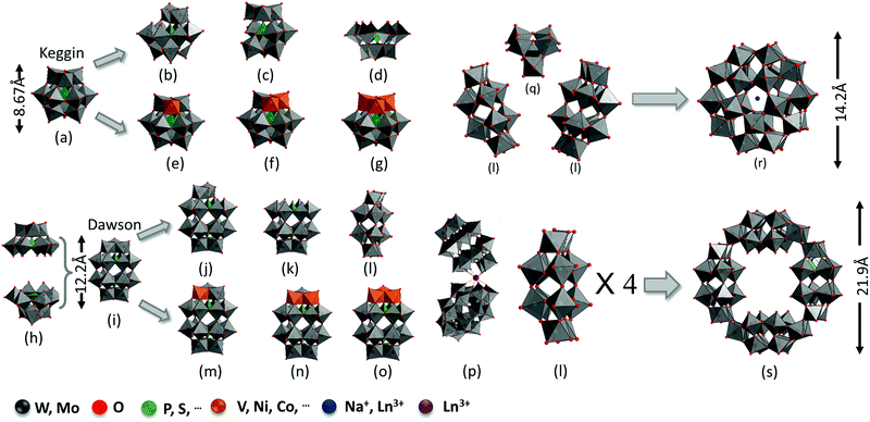
For the Keggin structure, the size of the polyanion is around 1 nm and its lacunary derivatives (XM11, XM10, and XM9) can be obtained by removing one to three {MO6} octahedrons.50–54 The lacunary sites can be filled with transition metals (such as V, Ni, Cu, and Co) to generate substituted Keggin structures (XM12−nYn, Y = V, Ni,…, n = 1–3) (Fig. 1a–g).55,56
In general, the molecular size for a Dawson (∼1.5 nm)-type structure is larger than that for a Keggin-type structure. The α-Dawson-type structure X2M18O64 can be regarded as the dimer of XM9. Moreover, rotating by 60° around the axis through both heteroatoms X would afford the β-isomer.57 The addenda atoms are partially removed or substituted by other elements to generate lacunary (P2W17, P2W15, and P2W12) or substituted Dawson structures. The general molecular formula of the substituted Dawson structures can be presented as X2M18−nYnO62n− (X2M18−nYn, X = P, Si,…; M = Mo, W; Y = V, Cr, Co,…; n = 1–3) (Fig. 1h–o).58–60 When a rare earth metal is introduced, two mono lacunary Dawson structures become connected to one rare earth metal to form another series of substituted Dawson structures (Fig. 1p). The assembly of two or several Keggin or Dawson fragments can form other types of complex structures such as X5M30O110n− (X5M30, Preyssler-type) and P8W48O184 (P8W48, crown-type). The X5M30O110n− structures can be regarded as the assembly of one XM6 and two X2M12 with Na+ or Ln3+ in the center of the cage (Fig. 1l, q and r).61 The P8W48O184 structure can be viewed as a regrouped structure of four P2W12 species (Fig. 1l and s).58,62 There are still more diverse POMs based on Dawson-type structures, which are available in previous review papers.63
POMs are a kind of inorganic EC materials; however, their preparation methods and properties are quite different from those of metal oxides. In general, POMs feature high solubility in water and in many organic solvents. Thus, POMs can be processed as a film through the solution process; however, after solvent evaporation, they form inhomogeneous films with aggregated particles. This results in very poor transparency in an ECD. Therefore, POM films for ECD are prepared simply via the electrodeposition method.
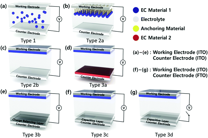
EC devices generally consist of a working electrode (WE), a counter electrode (CE), and an electrolyte layer. For a transparent electrochromic device, such as a smart window, WE and CE are transparent conductive electrodes (TCEs) such as indium tin oxide (ITO), fluorine-doped tin oxide (FTO), aluminium-doped ZnO (AZO), and a metal nanowire or mesh. The EC materials are introduced in the electrolytes as a solution mixture (Type 1) or coated on WE (Type 2, 3), as shown in Fig. 2. Typically, the soluble molecular-level organic EC materials are used as a mixture of an electrolyte (Type 1)64 or anchored on an electrode surface (Type 2a).65 Similarly, soluble EC polymers are used as a mixture of an electrolyte (Type 1)64 or coated on an electrode surface (Type 2b)66via solution casting, layer-by-layer (LBL) deposition,67 or the spray coating method. Most CPs are introduced as thin films on WE via various deposition processes such as electrochemical polymerization and solution casting, followed by chemical polymerization.68,69
The EC materials of transition metal oxides and POMs are introduced as a thin film on an electrode via several deposition methods such as thermal, electrochemical, solution casting, and LBL.70–72 These EC materials can be coated on WE (Type 2b). In addition, they can be coated on CE along with the other types (cathodic or anodic) of EC materials on WE to enhance the EC properties (a complementary ECD, Type 3a).73 The ECDs of Type 2 have a half-cell structure, while those of Type 3 exhibit a full-cell structure. Thus, Type 3 ECD can involve a charge balancing layer or a capacitive layer or both at CE (Type 3b–d). Among the ECD structures, Type 3b and 3c have recently emerged. Type 3b ECD contains a charge balancing layer (CBL) at CE,74 so that the color contrast becomes large, while the working voltage is reduced as the charge balancing condition is reached. In Type 3c ECD, WE is coated with an EC layer, while CE is coated with a transparent and capacitive layer. Type 3c ECD combines electrochromism with electrochemical capacitors in a single ECD to afford an EC capacitive window (ECCW) or EC energy storage (EES).
Since energy loss through windows can reach to about 50% of the total energy consumption in buildings, EC materials have been developed to maintain optical memory (OM) at both colored and bleached states under the voltage-off state (VOFF) (Type 3d).5 These bi-stable EC states are achieved when ECDs are under minimized interfacial electron transfer (IET) and interfacial dopant ion transfer (IDT) conditions. Bi-stable ECDs are developed by adjusting the highest occupied molecular orbital (HOMO) level of CPs; these are further used as the EC materials and an ionic liquid is used as the electrolyte of an ECD.5 POMs can be a good charge balancing redox shuttle to promote both bi-stability (Type 3d) as well as energy storage capacity (Type 3c). While the energy consumption to maintain their optical states is small in small-sized electronics within short-time use, it becomes significant for the operation of large-area smart windows. Thus, the combined properties of charge balancing and capacitive properties of POMs can provide new functions, such as bi-stability and energy storage capacity, for ECDs.
In this review, we provide a comprehensive introduction on the electrochromism of POMs, including the preparation method for EC films and the effect of structure and atomic composition of POMs on the EC performance. A perspective on possible research directions is also given.
2. Electrochromism in POMs
POMs can act as an electron reservoir, giving rise to mixed-valence colored state species without their structural changes.39 The EC properties of POMs were first reported in 1979.75 As EC materials, POMs have several unique advantages over other materials. From the point of view of the molecular structure, every structure has a precise content of atoms and a definitive connection mode to each atom. Although POMs are large molecules, similar to that observed for a polymer, their atomic composition and size are precisely controlled through a simple chemical synthetic process. Unlike electrochromic metal oxide materials, which may have less precisely controlled doping levels, the functional group of POMs can be stoichiometrically implemented to every unit, similar to the chemical modification of monomers for EC polymers, for high EC functions. POMs are types of inorganic EC materials, which show good UV stability similar to metal-oxide EC materials. In general, as EC materials, POMs combine the advantages of both polymer and inorganic EC materials.The EC phenomenon in POMs occurs through the following process. The electrons at the HOMO levels are injected into the vacant orbitals involved in the oxygen-to-metal (O → M) ligand-to-metal charge transfer (LMCT) transitions after applying a more negative potential than the energy levels of the vacant orbitals. The electrons injected into the high-energy levels may also be trapped by electron traps. When the applied potential (Vap) is more positive than the energy levels for the d1 electron states, these electrons are returned to the electrode, yielding electrochemical oxidation of POMs. The d1 electrons in the O → M LMCT states facilitate the absorption of visible light via intervalence charge transfer among metal centers and d–d transitions.25 For example, color changes by the reduction of P2W18O626− in an acidic electrolyte can be described by eqn (1)–(3):76
| P2W18O626− + e− = P2W18O627− | (1) |
| P2W18O627− + e− = P2W18O628− | (2) |
| P2W18O628− + 4e− + 4H+ = H4P2W18O628− | (3) |
Such electrochromism of POMs can be evaluated according to the properties listed below:
(1) Color contrast (ΔT, ΔA, ΔOD): the maximum transmittance, absorbance, and optical density difference between the bleached and colored states.77
(2) Response time (tc/tb): the time for coloration and bleaching. It can be determined from the time for a 90% transmittance or absorbance change under an applied voltage (Vap).
(3) Coloration efficiency (ηce): the optical density change (ΔOD) for the charge consumed per unit of electrode area. It can be calculated from the following eqn (4):
 | (4) |
(4) Cyclic stability: the ability to retain the initial EC properties, especially the contrast and response time, when an ECD is repetitively cycled between its colored and bleached states.78 In this review, if there is no special indication, the EC performance is reported for a three-electrode system, in which the EC film is coated on WE (ITO); also, a Pt wire is used as CE, and Ag/AgCl or a saturated calomel electrode (SCE) is used as the reference electrode in an aqueous electrolyte.
3. General methods for EC films and preparation methods for POM EC films
In general, EC films are prepared by several methods including the electrochemical method, dip-coating, spin-coating, spray coating, spray pyrolysis, chemical vapor deposition (CVD), thermal evaporation, and sputtering deposition. The electrochemical process can be classified into two categories such as electrodeposition and electropolymerization. Electrodeposition is a fast and economical method to prepare metal oxide EC films (like NiO, WO3, and V2O3) on TCE and it is also suitable for large-scale manufacturing.79–83 The electropolymerization method is usually applied for the preparation of polymer EC films.84–86 Dip-coating, spin-coating, and spray coating methods are applied for the preparation of EC films using soluble EC polymers and metal oxides.87 Spray pyrolysis is based on the thermal decomposition of salts, while a film is formed during the sintering process. This is a simple and relatively cost-effective method without vacuum for preparing V2O5-, WO3-, and NiO-based EC films.88–91 This method is adaptable for any shape of the substrate and is suitable for large-scale manufacturing.92The chemical vapor deposition (CVD) method is based on the chemical reaction of gaseous reactants at a heated substrate surface. PEDOT-, WO3-, MoO3-, and NiO-based EC films were prepared through CVD.93–101 Thermal evaporation involves heating a solid material inside a high-vacuum chamber until it produces vapor stream that traverses the chamber and sticks to the substrate as a film. It is commonly used to produce thin WO3, MoO3, and NiO EC films.102 Sputtering is a physical vapor deposition method, which requires a higher vacuum condition compared with the aforementioned methods. This method has been applied to prepare metal oxide (such as WO3, NiO, MoO3, and V2O5) films.103–106
For the preparation of POM-based EC films, a high temperature and vacuum are not used to avoid decomposition of the POM structure. Four different methods have been reported for preparing POM films, and these are tableting,75 spin-coating, layer-by-layer (LBL),107 and electrodeposition methods (Fig. 3).108
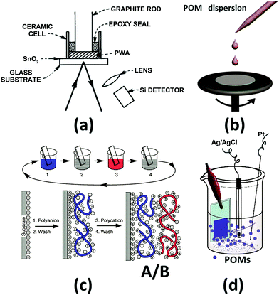 | ||
| Fig. 3 The illustration of the preparation methods for POM EC films. (a) Tableting method;75 Reproduced from ref. 75, Copyright 1979, with permission from AIP Publishing. (b) Spin-coating; (c) layer-by-layer (LBL) method;107 (c) Reproduced from ref. 107, Copyright 1997, with permission from AAAS. (d) Electrodeposition method.108 Reproduced from ref. 108, Copyright 2013, with permission from the Royal Society of Chemistry. | ||
In 1979, B. Tell and F. Wudl prepared a solid EC cell with H3PW12O40 (PW12) as an EC material. The powder-type PW12 was compressed (100 kg cm−2) to ∼1 mm thick and ∼3 mm diameter ceramic tube on an SnO2-coated glass (FTO). The contact of PW12 and the substrate was not good, which greatly limited the performance of the EC cell (Fig. 3a). Subsequently, this method is not used to prepare a POM-based EC film anymore;75 thus, the details of this method will not be included in this review.
POMs are quite soluble in various solvents, especially in water with water solubility up to 19 g/100 mL.109 However, almost all the EC experiments are carried out in an aqueous electrolyte, which can dissolve POM films. To avoid such dissolution of the POM films in water, a stabilizer is introduced to maintain the POMs in the film state without dissolution into the electrolyte. Furthermore, POMs easily crystallize and aggregate in a film state to result in a hazy film. Thus, a stabilizer is added to form a transparent film without haziness. These stabilizations and good dispersion of POMs in solid-state films are crucial for high EC performances. Therefore, ionic and polar stabilizers including large organic or polymeric cations, which induce cation–anion interaction, chemical bonding, or hydrogen bond interactions with POMs, are introduced in the POM solution. Conjugated polymers, carbon materials, and metal oxide-based semiconductors have been used as stabilizers to make a POM film through a solution and wet chemistry process for an ECD.
3.1 Spin-coating method
Spin-coating is an effective and low-cost method to prepare a homogeneous thin film and it has been used for POM-based EC films (Fig. 3b). Generally, if the EC films are examined in an aqueous electrolyte, the stabilizer and POMs should be mixed first and then, the mixture is spin-coated. If there is no stabilizer for POMs, the electrolyte should be in the solid state to avoid the dissolution of POMs.In 1994, Sanae et al. reported a POM-based EC film prepared by spin-coating.110 In 1997, a solution of [(CH3)2NC6H4NH(CH3)2]4[(C4H9)4N]SiMo12O40 in DMF was spin-coated to prepare an EC film, which showed color change from yellow to green and violet under the potential change from 1.0 V to 0 V and −1.0 V, respectively, (Fig. 4) in a 3-electrode cell.111 In the same year, an H5PMo10V2O40 film was prepared without any stabilizer and was applied to a solid-state EC window; it consisted of Li+-doped oxymethylene polyoxyethylene (OMPE) as the solid polymer electrolyte and Prussian blue-coated ITO as CE. A change in absorbance from 0.73 (−1.5 V) to 0.48 (1.0 V) was detected at 700 nm.112
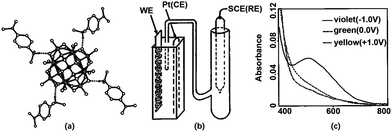 | ||
| Fig. 4 (a) Molecular structure of the complex; (b) the illustration of the configuration for cuvette cell; (c) absorption spectra of complex-based EC film at ① 1.0, ② 0, and ③ −1.0 V.112 Reproduced from ref. 112, Copyright 1997, with permission from American Chemical Society. | ||
In 2003, alkylammonium was used as a stabilizer to prepare alkylammonium molybdates (AAMs) (C18H37NH3)5HMo7O24 by spin-coating. AAMs showed a laminated super-lattice structure with a d-spacing of 3.45 nm and exhibited color changes under a negative potential.113
Although the spin-coating method for the preparation of POM films was considered until 2003, the EC response time, ΔT, and ηce of POM EC films prepared by the spin-coating method have not been reported. Since then, no reports have been found on the POM films for ECD prepared by the spin-coating method. This can be because the POM films obtained from solution-coating methods afford rather low ΔA (Fig. 4c) and POMs are easily aggregated after the removal of solvents, resulting in a hazy film.
3.2 Layer-by-layer method
In 1997, Gero Decher developed the LBL method, which can be easily carried out by the consecutive adsorption of polyanions and polycations.107,114 As shown in Fig. 3c, steps 1 and 3 represent the adsorptions of a polyanion and polycation, respectively; steps 2 and 4 are washing steps. The four steps form the basic building sequence for the simplest film architecture (A/B)n.107The LBL method began to spread rapidly and nearly all of the POM-based films were fabricated by using this method.115–119 An EC film prepared by LBL shows high transparency at the bleaching state and cyclic stability. In the LBL method, to prepare the POM EC film, commonly used polycations are PAH: poly(allylamine hydrochloride), PSS: poly(styrene sulfonate), PDDA: poly(diallyl dimethyl ammonium chloride), and PEI: poly(ethylenimine).
3.3 Electrodeposition method
The preparation of POM EC thin films by electrodeposition also needs a stabilizer or a substrate to load the POMs; however, it is a relatively new method. This method was reported in 2013 and has obvious advantages over the LBL method.108 The electrodeposition of POM films can be applied to Type 2–3 ECDs using different counter electrode materials on TCE. To meet the requirement of high transmittance at the bleached state, transparent porous TiO2 layers have often been employed as a substrate to host POMs. In order to establish stable interactions between TiO2 and POMs, TiO2 should be functionalized with –OH or –COOH groups, which form chemical interactions with the terminal oxygen of POMs. Ti–OH groups can form hydrogen bonding with the terminal oxygen of POMs. Meanwhile, in the acidic condition, the Ti–OH groups are converted to a protonated form (Ti–OH2+), yielding acid–base interactions with POM anions. Importantly, POMs show good chemical stability under acidic conditions except Nb- or Ta-based POMs.120–122 Through the electrochemical technique, POMs can be deposited easily on the TiO2 layer in acidic conditions.123,124The large surface area of TiO2 is beneficial for loading large amounts of POMs as compared to that for the LBL method, reducing the deposition time. Furthermore, the porous structure is advantageous for ion diffusion, which can result in small tc and tb values for the EC reaction. The high transparency of TiO2 is helpful for obtaining high ΔT, which makes the POM–TiO2 film an ideal candidate for a POM-based EC device. A duration of less than 15 minutes was required to make a film with high performance by using the electrodeposition method.108 For these reasons, POM-based EC films having various structures were prepared using this method.
4. Effect of the atomic composition and structure of POM on EC properties
Several basic structures of POMs are shown in Fig. 1. And they can be chemically manipulated to generate lacunary units by removing {MO6} octahedra. For the same molecular structure, POM derivatives with different atomic compositions can be generated by substituting {MO6} by other metal–oxygen octahedra. In the following section, the effect of the structure and atomic composition of POMs on the EC performance will be reviewed.4.1 The EC properties of Dawson and lacunary Dawson-type POMs
The lacunary Dawson structures are illustrated in Fig. 1j–l. The EC properties of POM films are affected by the number of the substituted metals or the degree of lacunary structures. Under the same Vap, the more the lacunary structures of the POM, the larger the optical contrast. Furthermore, λmax blue-shifted with an increased degree of lacunary structures. For example, λmax for PSS/PAH/(P2W18/PAH)20 at 650 nm blue-shifted to 630 nm for PSS/PAH/(P2W17/PAH)20 and to 585 nm for PSS/PAH/(P2W15/PAH)20.125 The ΔOD values of the EC films increased in the order PSS/PAH/(P2W18/PAH)20 < PSS/PAH/(P2W17/PAH)20 < PSS/PAH/(P2W15/PAH)20 under the same applied voltage range from 0 V to −0.8 V. The ECD with PSS/PAH/(P2W15/PAH)20 showed ΔA of 0.25 (Fig. 5a). | ||
| Fig. 5 (a) Solid lines: from top to bottom indicate the absorbance of ① PSS/PAH/(P2W18/PAH)20 at λmax = 650 nm, ② PSS/PAH/(P2W17/PAH)20 at λmax = 630 nm, ③ PSS/PAH/(P2W15/PAH)20 at λmax = 585 nm during double-potential steps (0 V to −0.8 V). Dotted line: the absorbance of PSS/PAH/(P2W15/PAH)20 during double-potential steps from 296 to 300 cycles;125 Reproduced from ref. 125, Copyright 2005, with permission from Elsevier. (b) P2W17/[CuII(phen)2]30 modified ITO during subsequent double-potential steps (−0.9V to 0.5V) at 650 nm;128 Reproduced from ref. 128, Copyright 2005, with permission from American Chemical Society. (c) UV-vis spectra of the [P2W17/PAH/P2W17/NR]35 film in the fully oxidized state (deep pink) and the fully reduced state at −0.9 V (dark purple-blue).129 Reproduced from ref. 129, Copyright 2009, with permission from Elsevier. | ||
According to DFT calculations,126 all six isomeric P2W18 species have the same electronic structure constituted in the fully oxidized state, showing two well-separated sets of energy levels with a distinct energy gap (2.22–2.48 eV) between the highest occupied molecular orbital (HOMO) and the lowest unoccupied molecular orbital (LUMO). The low-lying orbitals delocalize over the bridging O atoms, while the high-lying orbitals feature weak π-antibonding interactions between the metal dxy and bridging p orbitals of O atoms.
Interestingly, the calculation for the Dawson-type POMs indicated that the polar site {WO6} and equatorial site {WO6} do not contribute equally to the LUMO and LUMO+1 of POMs.126 The LUMO of these POMs is mainly centered on the equatorial site {WO6} rather than the polar site {WO6}. As a result, reduction occurs on the equatorial site {WO6}, which has been confirmed experimentally.127 This means that the reduction of POMs can be easier and better EC performances can be obtained if the equatorial site {WO6} is more exposed. According to this principle, P2W12 can feature a high EC performance. Nonetheless, P2W12 is not stable in aqueous solutions and tends to change into P2W17.58 P5W30 and P8W48, which are derived from P2W12, exhibit good EC properties, as will be reviewed in the following section. Since the equatorial sites {WO6} of the Dawson-type structures and their derivatives can be exposed more, generally speaking, the lacunary and substituted Dawson structures show enhanced EC performances.58
Several large cations, such as PSS and PAH, were employed to prepare a Dawson-type-based EC film using the LBL method. Wang et al. prepared PSS/Cu(phen)2/[P2W17/Cu(phen)2]30 and PSS/Fe(phen)3/[P2W17/Fe(phen)3]30 to show multicolor EC performances from light green, yellow, green to green blue (Fig. 5). PSS/Fe(phen)3/[P2W17/Fe(phen)3]30 displayed a color change from orange red to dark violet.128
Similarly, [P2W17/PAH/P2W17/NR]35 was prepared with the help of neutral red (NR). The multilayered film showed a multicolor change from deep pink to dark bluish-purple under the potential range from 0.2 V to −1.0 V (Fig. 5c ΔA). The coloring and bleaching times were 9.3 s and 9.6 s, respectively. It showed ΔA of 0.31 unit at 650 nm under the potential steps from 0.5 V to −0.9 V.129 In the presence of poly(vinyl alcohol) (PVA), the [PVA–P2W18/PAH]50 film showed both photochromic and EC properties.130
The P8W48 structure is a complicated lacunary Dawson-type structure. The P8W48 structure can be considered as a polymer of four P2W12 hex-vacant Dawson structures (Fig. 1l and s). Crown-type POMs (K28Li5H7P8W48O184·92H2O, P8W48) and ultrathin W18O49 nanowires (NWs) are prepared on ITO substrates by the LBL method (Fig. 6). The prepared [PSS(PEI/PSS)3(PEI/W18O49)30/(PEI/P8W48)20] film switched progressively between three optical states by applying different voltages. Under a positive bias, it showed transparent state (1.0 V to 0 V versus Ag/AgCl), while under a negative electrochemical bias, W18O49 NWs could selectively block NIR light through a plasmonic EC effect (−0.2 V to −0.6 V) (Fig. 6a, e and g). From −0.6 V to −1.0 V, the film of P8W48 absorbed a broad band of visible light (Fig. 6b, f and g).131 A smart window was fabricated using this composite film (Fig. 6d); however, an aqueous electrolyte was employed, which would be a disadvantage for long-term use. The EC properties for some examples of Dawson and lacunary Dawson-type POMs are summarized in Table 1.
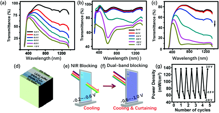 | ||
| Fig. 6 Transmission spectra of (a) [PSS(PEI/PSS)3(PEI/W18O49)30], (b) [PSS(PEI/PSS)3(PEI/P8W48)20], and (c) [PSS(PEI/PSS)3(PEI/W18O49)30/(PEI/P8W48)20] films at different potentials. The Vap values are 0.4 V, 0 V, −0.2 V, −0.6 V, −0.8 V and −1.0 V (from up to down) (d) schematic of an ECD; (e) the illustration of how the device realizes NIR blocking, (f) the illustration of how the device realizes dual-band blocking. (g) Power density change of the transmitted light through [PSS(PEI/PSS)3(PEI/W18O49)30/(PEI/P8W48)20] smart window by varying Vap. The device is at open circuit, −2.5 V for NIR-blocking state, −2.8 V for broadband-blocking state, and 2.0 V for transparent state.131 Reproduced from ref. 131, Copyright 2018, with permission from American Chemical Society. | ||
| No. | EC film | Fabrication method | Electrolyte | λ max, nm | V ap,b V | ΔT,c % (ΔAd) | t b/tce, s | Cycle stability | Ref. |
|---|---|---|---|---|---|---|---|---|---|
| a Using Pt and Ag/AgCl as the counter and reference electrodes, respectively. b Applied voltage. c Transmittance (%). d Absorbance change. e Response time. f Sodium acetate. | |||||||||
| 1a | PSS/PAH/(P2W15/PAH)20 | LBL | HOAc–NaOAcf buffer solution (pH 4.0) | 585 | −0.8/0 | (0.25) | 5.5/6.0 | 300 | 125 |
| 2a | PSS/Cu(phen)2/[(P2W17/Cu(phen)2)]30 | LBL | 0.2 M HOAc–NaOAcf buffer at pH = 3.5 | 650 | −0.9/0.5 | (0.24) | 6.6/6.5 | 200 | 128 |
| 3a | PSS/Fe(phen)3/[(P2W17/Fe(phen)3)]30 | LBL | 0.2 M HOAc–NaOAcf buffer at pH = 3.5 | 650 | −0.9/0.5 | (0.22) | 7.4/7.0 | 200 | |
| 4a | PSS(PEI/PSS)3(PEI/W18O49)30/(PEI/P8W48)20 | LBL | 0.10 M LiClO4 aqueous solution (pH = 5.0) | 500 | −1.0/0.4 | 35 | 26/86 | 131 | |
| 1060 | 52/86 | ||||||||
4.2. Transition- and lanthanide-metal–substituted Dawson-type POMs
For the TiO2(NP)–P2W15V3 EC film, ΔT at 555 nm under the Vap step from −1.8 V to 1.3 V was 91.8% and ηce was 176.8 cm2 C−1, indicating the best EC properties among those of these derivatives.132 The TiO2(NP)–P2W15V3 EC film showed color changes from transparent to blue and bluish-purple with the increase in negative potentials. However, for TiO2(NP)–P2W17V and TiO2(NP)–P2W16V2, no multi-color change was detected; they only showed color changes from transparent to blue with the increase in negative potentials. This multi-color EC switching (Fig. 7) can be attributed to the electron transfer from the polar site to the equatorial site. Thus, the electrons can be first attracted by the more electronegative V5+ on the polar site of the Dawson anion and then can be transferred to the W6+ anions on the equatorial site, which are easier to be reduced.
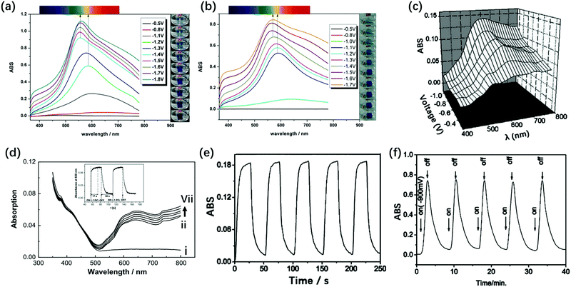 | ||
| Fig. 7 (a) Visible spectra of the α-P2W15V3-based EC film recorded under different potentials ranging from −0.5 V to −1.8 V. (b) Visible spectra of the α-P2W17V-based EC film under different potentials ranging from −0.5 V to −1.7 V;132 (a and b) Reproduced from ref. 132, Copyright 2015, with permission from the Royal Society of Chemistry. (c) In situ ΔA of [P2W17Ni/PAH]20 during different potentials from −0.4 V to −0.9 V.133 Reproduced from ref. 133, Copyright 2005, with permission from The Electrochemical Society. (d) Absorption spectra of self-assembled ITO/(PDDA/As2W15Mg3)4 films at open circuit (i), −0.5 (ii), −0.6 (iii), −0.7 (iv), −0.8 (v), −0.9 (vi) and −1.0 V (vii) Vap, inset: the response time test under open circuit to −1.0 V at 650 nm.134 Reproduced from ref. 134, Copyright 2008, with permission from Elsevier; (e) absorbance at 585 nm of the {[Ce(P2W17)2]/PAH}20 film-modified ITO during subsequent double-potential steps (−0.9 V to 0 V)135 (f) {[Ce(P2W17)2]/PAH}100 by potential turning on at −0.9 V and turning off.135 (e and f) Reproduced from ref. 135, Copyright 2004, with permission from the Royal Society of Chemistry. | ||
In 2004, Xu et al. prepared {[Ce(P2W17)2]}/PAH20 by the LBL self-assembly method. The response times of this material were tc = 4.0 s and tb = 5.5 s, respectively, and ΔA at 585 nm was 0.18 under Vap from −0.9 V to 0 V (Fig. 7e).135 The basic structures of Ce(P2W17)2 and P2W17Ni all consist of P2W17 blocks, while the substituted metal and substituted mode are different from each other. Compared with the result for the mono Ni-substituted Dawson (P2W17Ni) film, they show enhanced ΔA by 0.05 unit and a faster response time.
The Ln-substituted Dawson structure (Fig. 1p) also showed EC properties. In particular, the Ln-substituted series showed superior EC properties to the mono-transition metal–substituted Dawson structures. This can be observed because the Ln-substituted structures have 24 equatorial {WO6} units, while mono-transition metal-substituted ones have 12 equatorial {WO6} units. As described above, the more the equatorial {WO6} units, the higher the EC activities. Therefore, {[Ce(P2W17)2]/PAH}20 showed enhanced EC performances with ΔA of 0.75 at 585 nm under the potential steps from −0.9 V to 0 V. However, the response time became very long (tc = 108 s and tb = 350 s, respectively) (Fig. 7f).135
Due to their diversity in structure and atomic composition, the Dawson group of POMs can be a good EC model for understanding the structure–property relationship and for high-performance ECDs in the future. Some of the substituted POMs exhibit their intrinsic colors due to the presence of substituted metal ions. For example, the V-substituted and the Ni-substituted Dawson-type structures present orange and light green colors, respectively. Furthermore, the Ln-substituted Dawson-type structures show photoluminescence,136,137 which can be interesting for multi-functional ECDs. The EC properties of the transition and lanthanide metal–substituted Dawson-type POMs are summarized in Table 2.
| No. | EC film | Fabrication method (thickness) | Electrolyte | λ max, nm (at Vapb) | V ap,b V | ΔT,c % (ΔAd) | t b/tc,e s (ηce,f cm2 C−1) | Cycle stability | Ref. |
|---|---|---|---|---|---|---|---|---|---|
| a Using Pt and SCE as the counter and reference electrodes, respectively. b Applied voltage. c Transmittance (%). d Absorbance change. e Response time. f Coloration efficiency. g Using Pt and Ag/AgCl as the counter and reference electrodes, respectively. h Sodium acetate. | |||||||||
| 5a | TiO2(NP)–P2W15V3 | Electrodeposition (6 μm) | 0.1 M HCl aqueous solution | 555 (−1.4 to −1.8) | −1.8/1.3 | 91.8 | 3.5/3.9 (177) | 1000 | 132 |
| 577 (−1.3) | |||||||||
| 586 (−0.8 to −1.2) | |||||||||
| 6a | TiO2(NP)–P2W16V2 | Electrodeposition (6 μm) | 0.1 M HCl aqueous solution | 590 | −1.6/1.3 | 48.3 | 11.1/4.5 (47.8) | 1000 | |
| 7a | TiO2(NP)–P2W17V | Electrodeposition (6 μm) | 0.1 M HCl aqueous solution | 565 | −1.7/1.5 | 85.1 | 5.6/4.1 (67.7) | 1000 | |
| 8g | {[Ce(P2W17)2]/PAH}20 | LBL | 0.1 M HOAc–NaOAch buffer solution (pH ∼ 4.0) | 585 | −0.9/0 | (0.18) | 4.0/5.5 | 200 | 135 |
| 9g | {[Ce(P2W17)2]/PAH}100 | LBL | (0.75) | 108/350 | — | ||||
4.3. Preyssler-type POMs
Preyssler-type POMs showed a high EC performance, which could be attributed to the high ratio of equatorial {WO6} units in the structure (Fig. 1r). These Preyssler-type structures have more negative charges, which result in the enhancement of the POM coverage. Preyssler-type POMs have more negative charges than the Keggin- and Dawson-type POMs. Thus, Preyssler-type POMs are more effective species to make LBL films.In 2002, Liu et al. first identified the EC behavior of the Preyssler structure (Eu-P5W30:EuP5W30O11012−). The film of (PSS/PAH/Eu-P5W30/PAH)20 showed ΔA of 0.12 at 700 nm under the potential step from −0.4 V to −1.8 V. When the number of double layers reached 100, ΔA was enhanced to 0.7; however, the response time became very long up to 7 min (Fig. 8a).138 In 2006, ΔA of the film of PSS(P4VP/Na-P5W30)40 (Na-P5W30:NaP5W30O11014−) with poly(4-vinylpyridine) (P4VP) was reported as 0.28 under Vap of −2.1 V/0 V.139
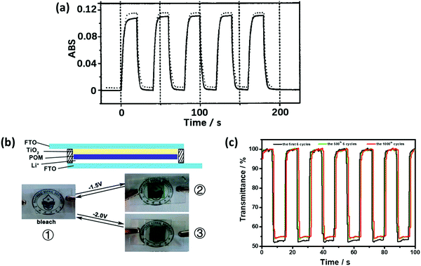 | ||
| Fig. 8 (a) ΔA at 700 nm of the (PSS/PAH/Eu-POM/PAH)20-coated ITO electrode during subsequent double-potential steps between −0.4 V and −1.8 V, showing the ΔA switching at the 1st (solid line) and 500th (dashed line) cycle; traces are offset for clarity. The response times of tc and tb were 4.2 and 4.4 s, respectively.138 Reproduced from ref. 138, Copyright 2002, with permission from John Wiley & Sons, Inc. (b) Illustration of the ECD structure of the X5W30 (X = P, S)-based smart windows. ① Photographic images of the bleached ECD, ② the P5W30-based ECD under −1.5 V, and ③ the S5W30-based ECD under −2.0 V. (c) At 650 nm, ΔT for the P5W30-based ECD during the subsequent double-potential steps between 0.5 V and −1.5 V.108 (b and c) Reproduced from ref. 108, Copyright 2013, with permission from the Royal Society of Chemistry. | ||
The films of TiO2(NP)–Na-P5W30 and TiO2(NP)–Na-S5W30 (Na-S5W30:NaS5W30O1109−) prepared by electrodeposition showed good EC performances in a Type 2a structure (Fig. 8). The response time of the TiO2(NP)–Na-P5W30 film was less than 2 s for both tc and tb values along with ΔT of 50% under the Vap step from −1.5 to 0.5 V at 650 nm (Fig. 8c). The TiO2(NP)–Na-S5W30 film showed small ΔT of 20% under Vap from −2.0 to 0.5 V at 550 nm. Obviously, the S5W30 derivative showed worse EC properties than the P5W30 derivative. This could be attributed to the S atom having higher electronegativity than the W atom, which makes {WO6} harder to be reduced in the S5W30 derivative.108 This suggests that the heteroatoms also have a great influence on the EC properties. Moreover, the porous morphology of WE contributed significantly to the enhancement in the performance. The EC properties of the Preyssler-type and isopolyoxometalates are compared in Table 3.
| No. | EC film | Fabrication method (thickness) | Electrolyte | λ max, nm | V ap,b V | ΔT,c % (ΔAd) | t b/tc,e s (ηce,f cm2 C−1) | Cycle stability | Ref. |
|---|---|---|---|---|---|---|---|---|---|
| a Using Pt and SCE as the counter and reference electrodes, respectively. b Applied voltage. c Transmittance (%). d Absorbance change. e Response time. f Coloration efficiency. g Using Pt and Ag/AgCl as the counter and reference electrodes, respectively. h Using FTO as the CE in 2-electrode device. i Lithium iodide. j Propylene carbonate. | |||||||||
| 10a | (PSS/PAH/Eu-P5W30/PAH)20 | LBL | pH 3.0 buffer solutions | 700 | −0.4/−1.8 | (0.09) | ≤420 | 500 | 138 |
| 11a | (PSS/PAH/Eu-P5W30/PAH)100 | LBL | (0.7) | 1800 | |||||
| 12g | (PDDA/W10)n (n = 3, 6, 10) | LBL | 0.1 M aqueous NaCl at pH = 2.5 | 650 | −0.8/0.4 | (0.025) | 5/65(3) | 60 | 140 |
| 15/70(6) | |||||||||
| 20/80(10) | |||||||||
| 13a | TiO2(NP)–W10 | Electrodeposition (4 μm) | 0.1 M H2SO4 aqueous solution | 550 | −0.8/0.5 | 49.5 | 7.2/4.9 | 100 | 141 |
| 14h | TiO2(NP)–Na-P5W30 | Electrodeposition (4 μm) | 0.1 M LiIi/PCj | 650 | −1.5/0.5 | 50 | 1/1 (711) | 1000 | 108 |
| 15h | TiO2(NP)–Na-S5W30 | Electrodeposition (4 μm) | 0.1 M LiIi/PCj | 550 | −2/1 | 23 | 1000 | ||
4.4. Isopolyoxometalate
The isopolyoxometalate (iso-POM) species is also a class of POMs, and it shows good EC properties. The most representative and simplest iso-POM is the W10 (W10O324−) structure (Fig. 9a). (PDDA/W10)6 was prepared in 1998. Under Vap from −0.8 V to open circuit, it shows small ΔA of 0.02 at 650 nm.140 The W10-based EC film was also prepared through electrodeposition on a porous TiO2 substrate, and it showed enhanced performance compared to the film prepared by the LBL method. The response times tc and tb were 7.2 s and 4.9 s, respectively, with ΔT of 47.1% at 550 nm under Vap from 0.5 V to −0.8 V (Fig. 9b).141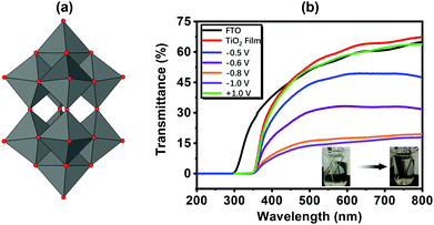 | ||
| Fig. 9 (a) The structure of W10; (b) the transmittance spectra of the FTO, TiO2 substrate and the EC film under different Vap.141 Reproduced from ref. 141, Copyright 2017, with permission from Elsevier. | ||
5. High-performance EC film based on TiO2 nanoparticle-POMs
TiO2 nanoparticles (NP) are widely used semiconductors in various areas and they have been demonstrated to be good stabilizers for POMs. The TiO2(NP)–POM composite film has been prepared through various processes such as sol–gel and impregnation methods.142–149 To prepare a transparent composite film for an EC application, a two-step process is often employed: (1) preparation of the TiO2 nanostructure dispersion or film and (2) the combination of POMs with TiO2. The hydrogen bond between the terminal oxygen of POMs and the surface hydroxyl groups (Ti–OH) of TiO2 is one reason for the combination of POMs and TiO2. Another reason is that under acidic conditions, the protonated TiO2 (Ti–OH2+) easily combines with POMs through an acid–base reaction, which can be realized by LBL and electrodeposition methods.150Based on the morphology of TiO2 and the film preparation process, TiO2(NP)–POM composite films with different morphologies were prepared (Fig. 10). First, TiO2(NP) with a diameter of 17.3 nm was used to prepare multilayer POM, yielding a flat condensed film (Fig. 10a). The [P2W18/PAH/P2W18/TiO2]10 multilayer film showed coloring and bleaching times of 15.4 s and 13.4 s, respectively, and ΔA at 650 nm was 0.12 units under Vap from 0.5 V to −0.9 V (Fig. 10b). The [P2W18/PAH/P2W18/TiO2]10 multilayer film achieved longer stability than the [P2W18/PAH]20 film after 1000 cycles of double potential steps (Fig. 10c). However, TiO2 did not significantly affect other properties such as response time and ΔT.76
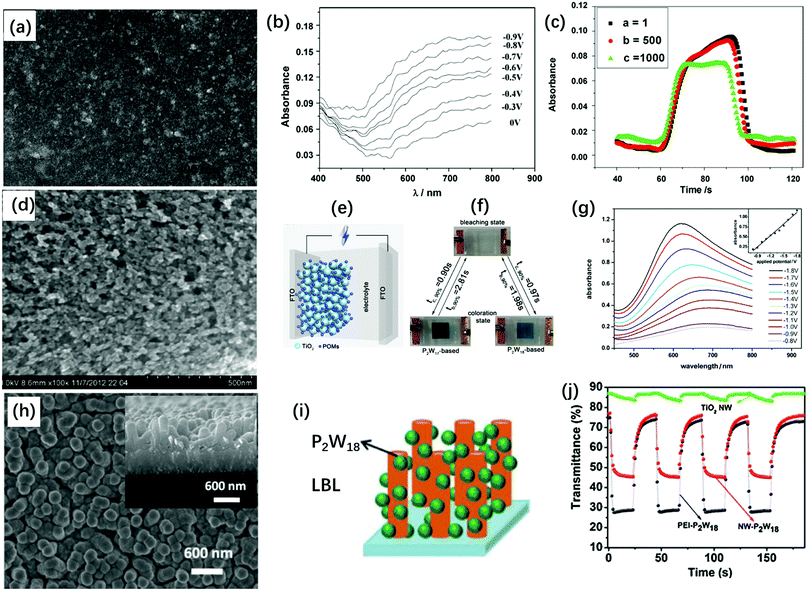 | ||
| Fig. 10 (a) SEM image of a [P2W18/PAH/P2W18/TiO2]10 multilayer film on a silicon wafer; (b) visible spectra of [P2W18/PAH/P2W18/TiO2]10-modified ITO glass electrode at different potentials. (c) The absorption changes for the double-potential step at a = 1, b = 500 and c = 1000 double-potential steps;76 (a–c) Reproduced from ref. 76, Copyright 2009, with permission from Elsevier. (d) The SEM images of the TiO2(NP)–P2W17 film on FTO; (e) the illustration of the structure of the POM-based smart windows; (f) the photos of the POM-based smart windows at bleaching and coloration states. (g) Visible spectra of the P2W17-based EC smart window under different potentials ranging from −0.8 V to −1.8 V. Inset: Plots of absorbance (at 620 nm) versus the Vap;49 (d–g) Reproduced from ref. 49, Copyright 2013, with permission from Elsevier. (h) SEM images of TiO2–[P2W18/PEI]40 films, inset: cross-sectional SEM image of TiO2-[P2W18/PEI]40 film; (i) schematic of formation of a TiO2(NW)–P2W18 film; (j) in situ transmittance curves for TiO2(NW)–[P2W18/PEI]40, [P2W18/PEI]40 and TiO2(NW) films at 650 nm under the potential step from 1.5 V to −1.5 V.151 (h–j) Reproduced from ref. 151, Copyright 2017, with permission from Elsevier. | ||
Second, Dawson-type POM films (TiO2(NP)–P2W18, TiO2(NP)–P2W17) were prepared through electrodeposition on a porous TiO2 substrate with 25 nm particle diameter. The film featured porous morphology, which would be beneficial for the fast diffusion of Li+. The composite films were assembled as Type 2b ECD using 0.1 M LiI propylene carbonate as the electrolyte and FTO as CE; the configuration is shown in Fig. 10e. For the P2W18–TiO2 film, ΔT was 48.7% under Vap of −1.9 V at 646 nm; the tc and tb values were 0.97 s and 1.98 s, respectively, and ηce was 176.8 cm2 C−1. This was nearly 10 times faster than the response time reported for [P2W18/PAH/P2W18/TiO2]10, which was possibly due to the optimized morphology of the TiO2(NP)–P2W18 film.49
Interestingly, the TiO2(NP)–P2W17 film showed high ΔT of 85.1% at the Vap step from −1.7 V to 1.0 V at 620 nm (Fig. 10g). The response times tc and tb of the TiO2(NP)–P2W17 film were 0.90 s and 2.81 s, respectively, along with high ηce of 205.3 cm2 C−1. Furthermore, the TiO2(NP)–P2W17 film showed a fast response time and high EC properties at near IR region (λmax = 1050 nm) under the Vap steps from −1.7 to 1.0 V with a contrast of 62.3%. These results also confirmed the principle discussed on the lacunary Dawson structures, which exhibit better EC performances than the saturated Dawson structures.
Third, in 2017, Liu et al. modified the LBL process for preparing the POM film, which was carried out on the surface of the TiO2 nanowire (NW) with the length of ∼600 nm and the diameter of ∼50 nm. TiO2(NWs) were covered by POMs via the LBL process; however, the pores between TiO2(NWs) were maintained to provide high surface areas and porosity. Under the Vap step from 1.5 V to −1.5 V, TiO2(NW)–[P2W18/PEI]40 showed ΔT of 45.1% at 650 nm with the response times of tc = 1.9 s and tb = 6.7 s (Fig. 10j).151
The P2W18 films with different morphologies were examined to reveal their morphology-dependent EC performance. The EC films having nanoparticle and nanowire structures exhibited nearly the same optical density around 50%, which was higher than that of the LBL film; this was mainly due to the higher content of P2W18 in NP and NW films than that in LBL films. The response time for the NP and NW films was significantly faster than that for the LBL film. The NP particle films featured larger pore sizes than the NW film, which would be beneficial for fast Li+ intercalation/deintercalation, resulting in a fast response time. The effects of the morphology on the EC response time were more obviously correlated between the porous films and the dense LBL film. Table 4 summarizes the EC properties of the TiO2–POM composite film.
| No. | EC film | Fabrication method (thickness) | Electrolyte | λ max, nm | V ap,b V | ΔT,c % (ΔAd) | t b/tc,e s (ηce,f cm2 C−1) | Cycle stability | Ref. |
|---|---|---|---|---|---|---|---|---|---|
| a Using Pt and SCE as the counter and reference electrodes, respectively. b Applied voltage. c Transmittance (%). d Absorbance change. e Response time. f Coloration efficiency. g Using Pt and Ag/AgCl as the counter and reference electrodes, respectively. h Using FTO as the CE in 2-electrode device. i Lithium iodide. j Propylene carbonate. k Sodium acetate. | |||||||||
| 5a | TiO2(NP)–P2W15V3 | Electrodeposition (6 μm) | 0.1 M HCl aqueous solution | 555 (−1.4 to −1.8) | −1.8/1.3 | 91.8 | 3.5/3.9 (176.8) | 1000 | 132 |
| 577 (−1.3) | |||||||||
| 586 (−0.8 to −1.2) | |||||||||
| 6a | TiO2(NP)–P2W16V2 | Electrodeposition (6 μm) | 0.1 M HCl aqueous solution | 590 | −1.6/1.3 | 48.3 | 11.1/4.5 (47.8) | 1000 | |
| 7a | TiO2(NP)–P2W17V | Electrodeposition (6 μm) | 0.1 M HCl aqueous solution | 565 | −1.7/1.5 | 85.1 | 5.6/4.1 (67.7) | 1000 | |
| 13g | TiO2(NP)–W10 | Electrodeposition (4 μm) | 0.1 M H2SO4 aqueous solution | 550 | −0.8/0.5 | 49.5 | 7.2/4.9 | 100 | |
| 14h | TiO2(NP)–Na-P5W30 | Electrodeposition (4 μm) | 0.1 M LiIi/PCj | 650 | −1.5/0.5 | 50 | 1/1 (71.1) | 1000 | 108 |
| 15h | TiO2(NP)–Na-S5W30 | Electrodeposition (4 μm) | 0.1 M LiIi/PCj | 550 | −2/1 | 23 | 1000 | ||
| 16a | [P2W18/PAH/P2W18/TiO2]10 | LBL (5 μm) | pH 2.0 HCl solution | 650 | −0.9/0.5 | (0.12) | 15.4/13.4 | 1000 | 76 |
| 17g | TiO2-(NW)–[P2W18/PEI]40 | LBL (600 nm) | 0.2 M, HOAc–NaAck pH = 3.4 | 600 | −1.5/1.5 | 45.1 | 1.9/6.7 (69) | 151 | |
| 18a | TiO2(NP)–PW11V | Electrodeposition (∼4 μm) | 0.1 M HCl aqueous solution | 650 | −1.5/1.5 | 75.8 | 15.6/8.7 | 1000 | 152 |
| TiO2(NP)–PW10V2 | 74.5 | 17.2/6.4 | |||||||
| TiO2(NP)–PW9V3 | 79.7 | 7.1/2.4 | |||||||
| 19a | TiO2(NP)–PW11V | Electrodeposition (∼4 μm) | 0.1 M LiClO4 PCj solution | 660 | −2.0/1.8 | 44.7 | 19.5/4.3 | 1000 | |
| TiO2(NP)–PW10V2 | 66.3 | 6.7/5.2 | |||||||
| TiO2(NP)–PW9V3 | 77.6 | 13.6/6.2 | |||||||
6. POM composite films with other metal oxides and carbon materials
6.1 POM composite films with other metal oxides
Besides TiO2, other metal oxides or semiconductors can also be used as stabilizers or linkers with POMs to prepare EC films. CdS nanoparticles (size: 11.6 nm) are employed to enhance the performance of the P2W17V-based EC films. Ma et al. prepared the {PEI/[P2W17V/PEI–CdS]30/P2W17V} film to show ΔT of 59.8% optical contrast at 573 nm along with tc/tb as 5.6/2.4 s under the Vap step from −1.1 V to 0 V. The CdS nanoparticles contributed to a large surface area, good conductivity, fast IETs with P2W17V and fast charge compensation by ions in the contacting liquid, which remarkably enhanced the EC performance of the composite film in comparison to that of the CdS-free film.153 In 2016, the composite film of WO3 sol (negatively charged) with P2W18 and PEI was prepared by the LBL method. WO3 and P2W18 synchronously contributed to the improvement in the EC properties. The optical contrast of the [PEI/P2W18/PEI/WO3]20 film at 650 nm under the polarization of −1.5 V/1.5 V was 48.4%, which was higher than those of [PEI/P2W18]40 (23.5%) and [PEI/WO3]40 (14.0%) films. The synergetic effect was attributed to the large surface area, which facilitated ion intercalation and de-intercalation.154Among the studies on POMs, the studies on Keggin-type POMs are far lesser than those on Dawson-type POMs. In contrast to the LUMO of the Dawson structures, the LUMO of Keggin-type structures is located on the polar sites according to DFT calculations.155 Therefore, a lacunary Keggin structure would have less EC-active units, which will not be beneficial for EC performance. However, in the saturated and substituted Keggin structures, the substituted atoms significantly affect the LUMO and lead to an enhanced EC performance.156,157 Therefore, the saturated and substituted Keggin structures are the best choices for EC materials among the Keggin structures.
Recently, SnO2 nanoparticles were used as the substrate to absorb PMo12 through the LBL process. Due to the large surface area, nano-SnO2/PDDA/PMo12 film was only deposited once. The conductivity of the film became higher with the help of SnO2. The response time was enhanced considerably; however, the optical contrast was still low (ΔT = 11%).158
The substituted Keggin-type structures are shown in Fig. 1e–g. In 2009, the SiW9V3 and Bi2O3 composite film was prepared using the LBL method. PEI-coated Bi2O3 nanoparticles were used as the polycations. The EC response times of the PEI/[SiW9V3/PEI-Bi2O3]15/SiW9V3 film were reported to be relatively fast: 7.0 s and 6.3 s for tc and tb, respectively. However, ΔA was low (0.03) under the potential steps from −1.0 V to 0 V at 678 nm (Fig. 11a). Nonetheless, the Bi2O3 nanoparticles incorporated in the films have the ability to shorten the response time and enhance the efficiency of photochromism.159
 | ||
| Fig. 11 (a) Absorbance at 678 nm of the {PEI/[SiW9V3/PEI-Bi2O3]15/SiW9V3} film-modified ITO during subsequent double-potential steps (−1.0 V to 0 V);159 Reproduced from ref. 159, Copyright 2009, with permission from American Chemical Society. (b) Visible spectra of the α-PW11V-based film in H+-based aqueous electrolyte under different Vap and (c) Li+-based non-aqueous electrolyte under different Vap.152 (b and c) Reproduced from ref. 152, Copyright 2016, with permission from the Royal Society of Chemistry. | ||
V-Substituted Keggin-type POMs PW12−nVn (n = 1, 2, 3) were prepared using the electrodeposition method. These films exhibited a good EC performance in both acid-aqueous and non-aqueous Li+/PC electrolytes (Fig. 11b and c).152 Most of the research on POM EC films has been carried out in acidic aqueous electrolytes. However, non-aqueous electrolytes would be beneficial for the stabilization of EC materials and devices.
6.2. POMs with carbon material and polymers
The combination of POMs with carbon materials and polymers is another attractive way to make POM-based EC films. There are several ways to realize non-covalent combination between carbon materials and POMs. First, using electrostatic interactions, many POM–carbon nanotubes (CNTs) and POM–graphene hybrids have been prepared (Fig. 12a).160–165 Thin films are prepared using the LBL method, which is also based on the electrostatic interactions (Fig. 12b).166–168 Second, π–π interaction with carbon materials affords a POM hybrid composite. This requires POMs functionalized with aromatic groups, which generates π–π interaction of POMs with the surface of CNTs or graphene (Fig. 12c).169,170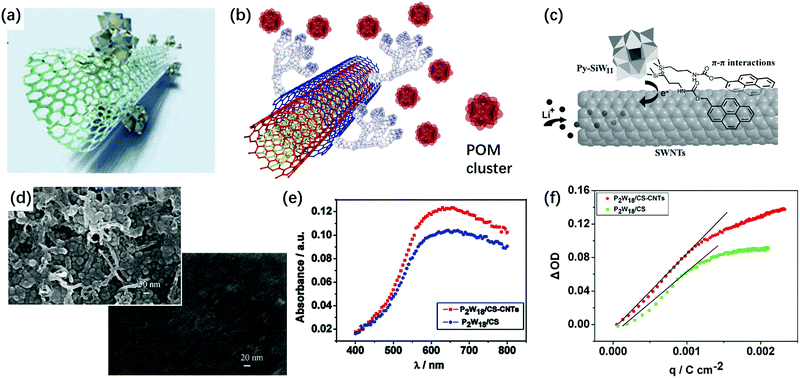 | ||
| Fig. 12 (a) The illustration of the POM cluster SWCNT composite.165 Reproduced from ref. 165, Copyright 2016, with permission from the Royal Society of Chemistry. (b) The illustration of POM cluster combined with polycation-decorated MWCNT.164 Reproduced from ref. 164, Copyright 2010, with permission from Springer Nature. (c) Schematic of POM-based hybrids to form the π–π interaction with the surface of the CNT or graphene.170 Reproduced from ref. 170, Copyright 2013, with permission from John Wiley & Sons, Inc. (d) The SEM images of [P2W18/CS-CNTs]30 film (up) and [P2W18/CS]30 film (down) on ITO-coated glass; (e) UV-vis spectra of [P2W18/CS-CNTs]30 and [P2W18/CS]30 films under a constant potential of −0.9 V; (f) ΔOD versus the extracted charge density of [P2W18/CS-CNTs]30 and [P2W18/CS]30 films.171 (d–f) Reproduced from ref. 171, Copyright 2011, with permission from Elsevier. | ||
The pyrene-based compound is a good linker between POM and CNTs. There are two ways to use a pyrene-based compound as a linker. The lacunary POM site can be covalently functionalized with a pyrene compound and then, pyrene-modified POM hybrids can be used for the non-covalent sidewall functionalization of single-walled CNTs (SWCNTs). For example, 1-pyrenemethylamine hydrochloride (PMA) was reported as a linker between CNTs and P2W18. In this sample, P2W18 structures were well-dispersed on the CNT surface to provide effective interfacial electron transfer (IET) between CNT and P2W18.114
Surfactants are also used as linkers between POMs and CNTs. Hong's group used cellulose sodium salt and Triton X-100 as the linkers to adsorb PMo12 on SWNTs. Efficient IET occurs from nonionic Triton X-100/CNT to PMo12. However, with the anionic surfactant (cellulose sodium), there is no IET between them.18 In 2011, as an alternative stabilizer for POMs, Xu's group used chitosan (CS) as a linker to form a stable P2W18/CS-CNTs composite film by the LBL method. The film with CNTs showed porous morphology and the film without CNT showed a flat dense surface. Under the potential step from −0.9 V to 0.5 V, ηce of the [P2W18/CS-CNTs]30 film at 620 nm was 91.5 cm2 C−1, while ηce for [P2W18/CS]30 was 74.7 cm2 C−1, indicating that CNTs can assist in enhancing the performance of the EC film. Nonetheless, the optical contrast was still low (20.3%) (Fig. 12d–f).171
The [P2W18/PAH/P2W18/PEDOT]20 composite film was prepared by the combination of LBL and electropolymerization. Here, PEDOT could be regarded as a linker for P2W18. The optical contrast of the [P2W18/PAH/P2W18/PEDOT]20 film was 54.7% under a potential step from −1.5 V to 1.0 V, which was higher than those of the [P2W18/PAH]40 (42.3%) and electropolymerized PEDOT (20.3%) films. Both P2W18 and PEDOT synchronously contributed to the enhancement in the EC properties.172 The EC properties of the POM composite films with other metal oxides and carbon materials are summarized in Table 5.
| No. | EC film | Fabrication method (thickness) | Electrolyte | λ max, nm | V ap,b V | ΔT,c % (ΔAd) | t b/tc,e s (ηce,f cm2 C−1) | Cycle stability | Ref. |
|---|---|---|---|---|---|---|---|---|---|
| a Using Pt and SCE as the counter and reference electrodes, respectively. b Applied voltage. c Transmittance (%). d Absorbance change. e Response time. f Coloration efficiency. g Using Pt and Ag/AgCl as the counter and reference electrodes, respectively. h Phosphate buffered saline. i Propylene carbonate. j Sodium acetate. | |||||||||
| 20g | {PEI/[P2W17V/PEI–CdS]n}/P2W17V | LBL (411 nm for 20 layers) | 0.05 M NaH2PO4–Na2HPO4 buffer solutions (PBS,h pH = 7.0) | 573 | −1.1/0 | 22.7, 45.3, 59.8 (0.11, 0.26, 0.39) | 3.2/1.9 (24.33) | 153 | |
| 5.6/2.1 (29.77) | |||||||||
| 5.6/2.4 (38.29) | |||||||||
| 21g | [PEI/P2W18/PEI/WO3]20 | LBL (20 layers, ∼1 μm) | 1 mol L−1 LiClO4 in PCi | 650 | −1.5/1.5 | 48.4 | 24.9/2.4 (46.1) | 154 | |
| 22g | Nano-SnO2/PDDA/[PMo12O40] | LBL (2.1 μm) | 0.1 M Na2SO4 (pH = 5.5) | 700 | −0.7/0.2 | 11 (0.045) | 1/1 (3.5) | 158 | |
| 23a | PEI/[SiW9V3/PEI–Bi2O3]15/SiW9V3 | LBL (15 layers) | 0.2 M HOAc–NaOAcj (pH = 3.82) buffer solutions. | 678 | −1.0/0 | (0.03) | 7.0/6.3 (7.8) | 200 | 159 |
| 24g | [P2W18/PAH/P2W18/PEDOT]20 | LBL, with PEDOT (6 μm) | 0.1 M LiClO4 in Na2SO4–H2SO4 buffer solution (pH = 3) | 600 | −1.5/1.0 | 54.7 | 2.45/1.41 | 20 (1.0/−1.5 V); 1500 (1/−1 V) | 172 |
| 25g | [P2W18/CS-CNTs]30 | LBL | HOAc–NaOAcj buffer solution (pH = 4) | 620 | −0.9/0.5 | 20.3 | 4.3/3.7 (91.5) | 1000 | 171 |
7. POM composite films for bistable and capacitive EC windows
EC devices with POMs generally consist of a POM-coated WE, an electrolyte layer, and a CE (like Type 2b), as described above. In order to improve the EC properties and add additional functionalities, CE can be coated with other EC materials (Type 3a) or with charge balancing materials (Type 3b). Furthermore, for a complete EC reaction, a full-cell structure is necessary to reach charge balancing between WE and CE. Thus, the performance of ECDs with CBL on CE would be better than that of ECDs without CBL. In Type 3a, EC reactions can be charge balanced with counter EC materials; however, the optical contrast would be worse than that in Type 3b because of the intrinsic color of the EC materials of CE in Type 3a.A recent study has revealed that transparent TiO2 thin films can provide charge balancing property for the EC reaction of a CP.6 In this study, the CP underwent cathodically coloring EC switching according to the following reactions:
| (Pol*) + n(A−C+)s ⇄ (Pol+nAn−) + ne− + nC+ | (5) |
| (CE*) + ne− + nC+ ⇄ (CE−nCn+) | (6) |
 | (7) |
 is the formal potential of TiO2; n is the number of electrons transferred from the EC film to the external circuit; f and t are the fractions of the reduced TiO2 and the thickness of the TiO2 film, respectively; F, R, and T are the Faraday constant, universal gas constant and absolute temperature, respectively; and ηCE and iRce are the potential drop caused by the ohmic resistance at CE and the overvoltage on CE, respectively. As a result, Ewe was enhanced by increasing the thickness of the TiO2 layer, which functioned as CBL. In this manner, the working voltage of ECD could be reduced and overvoltage could be determined via a dual potential measurement system. Although this system requires a thick TiO2 layer, TiO2 nanoparticle layers cannot be made as a thick film due to their poor electrical conductivity. Instead, it can be coated with redox-active species such as POMs.
Since POMs can reversibly accept and donate electrons without structural changes, they can act as CBL or CBL assistant. In particular, with TiO2 as the stabilizer, it can shuttle the redox reaction for EC switching and improve the EC properties of a conjugated polymer-based ECD, thus achieving bistable ECD and ECCW, as described below.173
The LUMO level of PW12 is slightly lower than the conduction band of TiO2.174 Thus, when combined with TiO2, the reduced TiO2 can transfer electrons to PW12, which functions as a redox shuttle. To explore the charge balancing effect, a TiO2(NP)–PW12 composite for the EC polymer devices, PW12, was electrodeposited on a TiO2-coated electrode using the reduction of W(VI) (eqn (8)) through the cyclic voltammetry (CV) method.173 SEM and energy-dispersive spectroscopy (EDS) mapping of the cross-section of the TiO2(NP)–PW12 samples with different TiO2 thicknesses showed that PW12 was uniformly coated not only on the surface but also in the pores between the TiO2 nanoparticles as an ultrathin film over the entire TiO2 layer (Fig. 13).
| n[PWVI12O403−] + nTiO2(e−) + nH+ → n[HPWV12O403−–TiO2] | (8) |
| PW12O403− + e− → PW12O404− | (9) |
| PW12O404− + e− → PW12O405− | (10) |
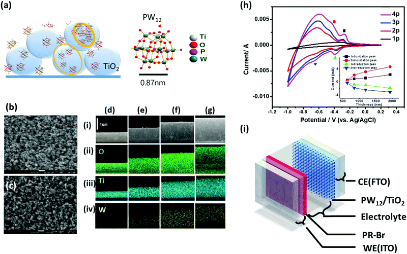 | ||
| Fig. 13 (a) Illustration of PW12 coating on TiO2. (b and c) Top-view SEM images of (b) 1930 nm thick TiO2 layer (4) and (c) PW12 composite (4p). (d–g) Cross-section SEM images of TiO2(NP)–PW12 layer with the TiO2 thicknesses (t) of 633 nm (1p), 845 nm (2p), 1190 nm (3p), and 1930 nm (4p) (row i, respectively; rows ii–iv): EDS mapping of (ii) O, (iii) Ti, and (iv) W elements on the cross-section of 1p–4p. (h) CV curves of 1p–4p on FTO in an aqueous solution of LiClO4 (0.1 M) (V versus Ag/AgCl) with a scan rate of 100 mV s−1 using Pt sheet as a CE. The inset shows the correlation of the peak current density against the PWTNF thickness. (i) Scheme of ECCW with PR-Br (180 nm)-coated ITO electrode (WE); PW12-coated TNF on FTO (CE) with different thicknesses, BMIM-TFSI (electrolyte) layer with a 100 μm-thick spacer.173 Reproduced from ref. 173, Copyright 2019, with permission from John Wiley & Sons, Inc. | ||
The redox peaks for TiO2 appeared in a more negative range. The redox reaction for the TiO2(NP)–PW12 film-coated electrode can be described below (eqn (11)):
| TiO2 + e− ⇄ TiO2(e−) | (11) |
It is well-known that the POMs exhibit cathodically coloring electrochromism in H+- and Li+-based electrolytes via the insertion of these small ions into reduced POMs.108,132 However, POMs did not show any color or transmittance changes when subjected to potential cycles from −1.0 V to 2.0 V (versus Ag/AgCl) in 1-butyl-3-methylimidazolium bis(trifluoromethylsulfonyl)imide (BMIM-TFSI) (Fig. 13b(ii) and (iv)) possibly due to the large BMIM cations (6.5 Å),176 which cannot intercalate with POMs. It has been reported75,108,132,177–179 that POMs cannot show obvious color change if there is no small cation (such as H+ and Li+) intercalation. Thus, the above TiO2(NP)–PW12-coated electrode can be safely used as a non-EC charge balancing electrode without causing unwanted loss of the color contrast for CP-based ECD.
A type 3b EC window was prepared with five layers (Fig. 13i): the EC polymer poly(3,3-bis(bromomethyl)-3,4-dihydro-2H-thieno[3,4-b][1,4]dioxepine)s (PR-Br)-coated electrode (working electrode, WE); the TiO2(NP)–PW12 film-coated electrode (CE); and the electrolyte layer sandwiched between WE and CE. The 180 nm-thick PR-Br layer was used as the EC layer (eqn (5)) and BMIM-TFSI was used as the electrolyte layer.
ECD shows a large transmittance change between −0.2 V and 1.2 V (versus Ag/AgCl) (Figure 14b(iii)). Interestingly, Tb was highly dependent on the TiO2(NP)–PW12 film composition, which affected the switching voltage and the optical contrast of the ECD. Therefore, even in the low switching voltage condition, ECD with optimized TiO2(NP)–PW12 film composition showed maximum Tb of 70% or higher. Moreover, in the presence of PW12, it was possible to reduce the thickness of the TiO2 film at CE by ≈2.3 times, which could eventually decrease the thickness of ECD.
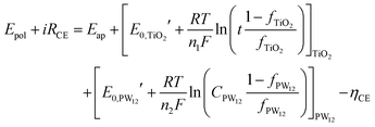
In a two-electrode EC system, Vap is distributed between WE and CE. It is important to obtain the highest potential at WE (Epol) with the lowest Vap value to maximize the optical contrast with long-term stability. Epol depends on Vap and Ece, which must be originating from the charge-balancing capacity of TiO2 and PW12, as presented in eqn (12) and (13).
| TiO2*film + ne− ⇄ TiO2*(e−)film | (12) |
| [PWVI12O403−]n + TiO2(e−)film ⇄ [PWVI12O403−–TiO2(e−)]film | (13) |
The fraction of charge balancing species at CE can be represented for the two species PW12 and TiO2 by the thickness of the TiO2 layer (t) and the content of PW12(CPW12) in the TiO2 layer, respectively. Then, the Nernst equation can be modified as eqn (14) and (15):
 | (14) |
 | (15) |
 and
and  are the formal potentials of TiO2 and PW12, respectively; n1 and n2 are the electrons accepted by TiO2 and PW12, respectively; n1 + n2 is equal to the number of electrons (n) transferred from PR-Br to ITO; and fTiO2 and fPW12 are the fractions of TiO2 and PW12 in CE.
The energy levels of PW12 are compared with those of PR-Br and TiO2 in Fig. 14.173 The LUMO values of TiO2 and PW12 are −4.0 and −4.73 eV, respectively. Thus, electrons from TiO2 can be transferred efficiently to PW12 and TiO2 during the charge-balancing reaction between WE and CE. Although only a small amount of PW12 (4.8–14.9 μg) is present in TiO2, the PW12 effect in ECD is significantly enhanced (Fig. 15a). Only 1.2 μm thickness of TiO2(NP)–PW12 is needed for the best performance of ECD; however, without PW12, for the best performance of the ECD, a 3.4 μm TiO2 film should be used as CBL. In other words, a small amount of PW12 in TiO2 results in the increase in the thickness and weight of TiO2 for the charge-balancing electron transport. This indicates that the ultrathin PW12 coatings function as a redox shuttle for deriving high-color-contrast ECDs.173 Due to the optimized charge-balancing, the cyclic stability of the PW12-containing ECDs notably increased (Fig. 15d).
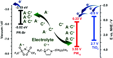 | ||
| Fig. 14 A mechanism of the charge-balancing effect by PW12.173 Reproduced from ref. 173, Copyright 2019, with permission from John Wiley & Sons, Inc. | ||
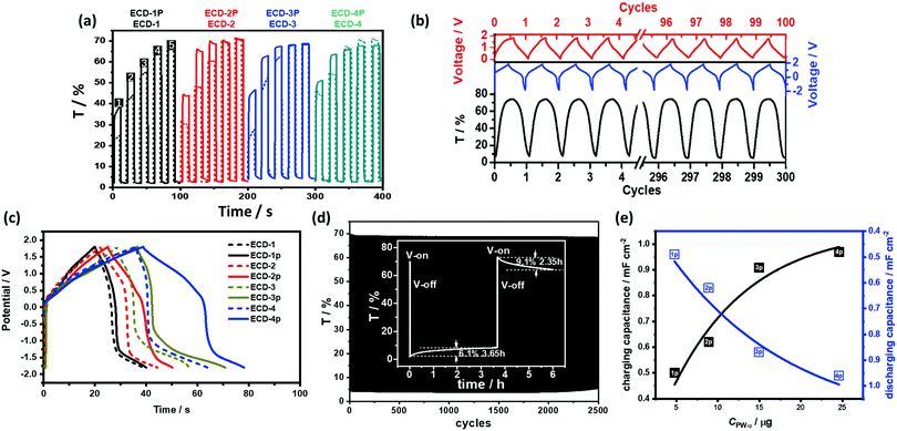 | ||
Fig. 15 (a) Transmittance change of the ECD-1–4 and ECD-1p–4p under different Vap at 580 nm under a different Vap condition (1![[thin space (1/6-em)]](https://www.rsc.org/images/entities/char_2009.gif) : :![[thin space (1/6-em)]](https://www.rsc.org/images/entities/char_2009.gif) 1.0/−2.0 V, 2 1.0/−2.0 V, 2![[thin space (1/6-em)]](https://www.rsc.org/images/entities/char_2009.gif) : :![[thin space (1/6-em)]](https://www.rsc.org/images/entities/char_2009.gif) 1.3/−2.0 V, 3 1.3/−2.0 V, 3![[thin space (1/6-em)]](https://www.rsc.org/images/entities/char_2009.gif) : :![[thin space (1/6-em)]](https://www.rsc.org/images/entities/char_2009.gif) 1.5/−2.0 V, 4 1.5/−2.0 V, 4![[thin space (1/6-em)]](https://www.rsc.org/images/entities/char_2009.gif) : :![[thin space (1/6-em)]](https://www.rsc.org/images/entities/char_2009.gif) 1.8/−2.0 V, and 5 1.8/−2.0 V, and 5![[thin space (1/6-em)]](https://www.rsc.org/images/entities/char_2009.gif) : :![[thin space (1/6-em)]](https://www.rsc.org/images/entities/char_2009.gif) 2.0/−2.0 V) (b) charging and discharging cycles for ECD-3p (blue, solid line) and the simultaneous transmittance change (black) up to 300 cycles under 1.5/−2.0 V, and charging/discharging cycles for ECD-3p under 0/1.8 V (red); (c) charging and discharging test of the ECCWs at the current of 0.2 mA (voltage scale from −1.8 V to 1.8 V) for ECDs having different TiO2(NP)–PW12 thicknesses: 1P = 633 nm, 2P = 845 nm, 3P = 1190 nm, 4P = 1930 nm. (d) Cyclic stability of ECD-3p for Vs of 1.8/−1.8 V; inset: the bistability of ECCW-3p for 3.5 and for 2.35 h after voltage-off from −2.0 and 1.5 V, respectively. (e) Correlation between the PW12 content and the charging/discharging capacitance for ECD-1p–4p.173 Reproduced from ref. 173, Copyright 2019, with permission from John Wiley & Sons, Inc. 2.0/−2.0 V) (b) charging and discharging cycles for ECD-3p (blue, solid line) and the simultaneous transmittance change (black) up to 300 cycles under 1.5/−2.0 V, and charging/discharging cycles for ECD-3p under 0/1.8 V (red); (c) charging and discharging test of the ECCWs at the current of 0.2 mA (voltage scale from −1.8 V to 1.8 V) for ECDs having different TiO2(NP)–PW12 thicknesses: 1P = 633 nm, 2P = 845 nm, 3P = 1190 nm, 4P = 1930 nm. (d) Cyclic stability of ECD-3p for Vs of 1.8/−1.8 V; inset: the bistability of ECCW-3p for 3.5 and for 2.35 h after voltage-off from −2.0 and 1.5 V, respectively. (e) Correlation between the PW12 content and the charging/discharging capacitance for ECD-1p–4p.173 Reproduced from ref. 173, Copyright 2019, with permission from John Wiley & Sons, Inc. | ||
As described before, an ECD with low-HOMO-level EC polymers and ionic liquid electrolytes can block IET and IDT to provide a bistable ECD. In the presence of PW12, the optical contrast loss was determined as 6% for 3.5 h and 9% for 2.35 h after voltage-off from −2.0 and 1.5 V, respectively, showing improved bistability of the ECD (Fig. 15d, inset).
Concurrently, POMs are good candidates for a pseudocapacitor180,181 because they function as an electron reservoir. Although the EC polymer in the above-mentioned ECD is not a good capacitor and the electrolyte is an acid-free ionic electrolyte, the capacitance from the above PR-Br/BMIL-TFSI/TiO2(NP)–PW12 system is notable when subjected to a constant current charge and discharge condition (Fig. 15c, solid line). This can provide ECCW that combines electrochromism and an energy storage system. The capacitance of the ECCW based on PR-Br/BMIL-TFSI/TiO2(NP)–PW12 increased with the thickness of TiO2(NP)–PW12 or the content of PW12 (Fig. 15e) until it reached the resistance limit. In addition, the Coulombic efficiency for each complete cycle for these ECCWs was >98%, which was higher than that of the corresponding ECCW without PW12. The charging process was simultaneously accompanied by the color change of ECCW and even after the extended galvanostatic charging–discharging cycles, no optical loss was found (Fig. 16b).
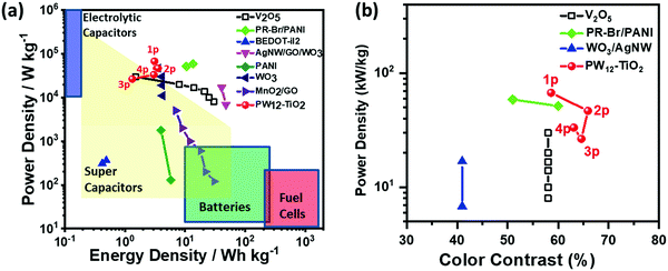 | ||
| Fig. 16 (a) Ragone plot of various electrochemical capacitors. (b) Figure of merit for color contrast against power density for various EC capacitors.173 Reproduced from ref. 173, Copyright 2019, with permission from John Wiley & Sons, Inc. | ||
Because all the materials in this ECCW are not traditional supercapacitor materials, the capacitive performances were lower compared to that of the traditional supercapacitors. However, the thicknesses of the EC materials and redox shuttle (POM) are quite low; thus, the power density of this ECCW was higher than that of various oxides and conjugated polymer systems,182–189 which often use acidic electrolytes (Fig. 16a). Since the ECCWs with TiO2(NP)–PW12 use acid-free ionic electrolytes, it can provide a way to develop a non-aqueous EC capacitor with high color contrast and long cyclic stability (Fig. 15b). Fig. 16b shows a high figure-of-merit for color contrast against power density (fPDT) for several ECCWs. The TiO2(NP)–PW12 system showed the highest figure of merit for the color contrast among the ECCWs in Fig. 16b. Taking advantage of the high color contrast and power density, it was possible to use the TiO2(NP)–PW12 system for lightening an LED (Fig. 17) via energy transfer from the charged ECCW to the LED.
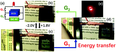 | ||
| Fig. 17 (a) The equivalent circuit used in lighting an LED. (b and c) Photographic images on the color switching of ECCW (ECD-3p) at (b) −2.0 V and (c) 1.8 V; and (d) under bias free condition, at which ECCW transferred energy (discharge) to the LED for lighting upon G1 connection. The photographic image of the LED lit under a dark environment is shown in (e).173 Reproduced from ref. 173, Copyright 2019, with permission from John Wiley & Sons, Inc. | ||
8. Conclusion and perspective
POMs consist of a 3-dimensional close-packed metal oxide framework and act as an electron reservoir, giving rise to mixed-valence colored state species without their structural changes. As a unique feature, POMs can be designed at the molecular level. The two basic structures of Keggin and Dawson type POMs can generate several derivatives such as lacunary, complex and substituted structures. Among the huge family of Dawson-type POMs, only α-Dawson and its derivatives are the most widely used structures in the POM EC films. While the color of the POM molecules is affected by the number of the substituted metal, M, or the degree of lacunary structures, the more the lacunary structures of POM, the larger the EC optical contrast. Furthermore, λmax blue-shifted with the increase in the degree of lacunary structures. Generally, the EC properties of the Dawson structures are better than those of the Keggin structures and the EC properties of the lacunary structures are better than those of the saturated structures. Stabilizers are introduced for the preparation of a stable and transparent POM film. Large organic cations, polycations, carbon materials, and metal oxide semiconductors have been researched as stabilizers and linkers. Therefore, the EC properties of POMs can be improved not only by the structural and atomic variation of POMs but also by the selection of stabilizers and linkers. Among the stabilizers, TiO2(NPs) have been examined widely and show very high EC optical contrast and long cyclic stability. Other metal oxides and carbon materials have emerged as stabilizers and contribute to finding new functionalities. Over the years, it has been demonstrated that POMs are promising candidates for EC applications. Until now, the TiO2(NP)–P2W15V3-based EC film showed the highest optical contrast of 91.8% in an aqueous electrolyte. The TiO2(NP)-P5W30 composite film showed the shortest response time of less than 1 s in a non-aqueous electrolyte with cyclic stability of over 1000 cycles. However, most of the studies on EC performance for POMs have been carried out in a half cell using a three-electrode system. Since the practical application requires a full cell (Type 3), there are still many factors to be understood to develop a highly efficient POM-based ECD. For example, the electrolyte, CE, and device structure should cooperate to afford an ECD with high optical contrast, fast response time, and high coloration efficiency. Furthermore, POMs find new functions in EC devices as a (1) redox shuttle in the charge balancing reaction and (2) capacitive materials. Even with an ultra-thin coating of POM, one can find a drastic change in driving voltage and large enhancement in the energy storage effect. A perspective on possible research directions is also given along with POM materials for new emerging integrative devices.Abbreviations
| P2W18 | [P2W18O62]6− |
| P2W17 | [P2W17O61]10− |
| P2W15 | [P2W15O56]12− |
| P2W12 | [H2P2W12O48]12− |
| P2W17V | [P2W17VO62]7− |
| P2W16V2 | [P2W16V2O62]8− |
| P2W15V3 | [P2W15V3O62]9− |
| P2W17Ni | [P2W17O61Ni(H2O)]8− |
| As2W15Mg3 | [As2W15Mg3O62]18− |
| Ce(P2W17)2 | [Ce(P2W17O61)2]17− |
| Na-P5W30 | [NaP5W30O110]14− |
| Eu–P5W30 | [Eu(OH2)P5W30O110]12− |
| S5W30 | [NaS5W30O110]9− |
| P8W48 | [P8W48O184]40− |
| PW12 | [PW12O40]3− |
| PW11V | [PW11VO40]4− |
| PW10V2 | [PW10V2O40]5− |
| PW9V3 | [PW9V3O40]6− |
| SiW9V3 | [SiW9V3O40]7− |
| PMo12 | [PMo12O40]3− |
| ECDs | Electrochromic devices |
| EC | Electrochromic |
| POMs | Polyoxometalates |
| CPs | Conjugated polymers |
| CE | Counter electrode |
| LBL | Layer-by-layer |
| ECCW | EC capacitive Window |
| EES | EC energy storage |
| OM | Optical memory |
| V OFF | Voltage-off state |
| V ap | applied potential |
| IET | Interfacial electron transfer |
| IDT | Interfacial dopant ion transfer |
| O → M | Oxygen-to-metal |
| LMCT | Ligand-to-metal charge transfer |
| η ce | Coloration efficiency |
| WE | Working electrode |
| SCE | Saturated calomel electrode |
| CVD | Chemical vapor deposition |
| OMPE | Oxymethylene polyoxyethylene |
| PAH | Poly(allylamine hydrochloride) |
| PSS | Poly(stryenesulfonate) |
| PDDA | Poly(diallyl dimethyl ammonium chloride) |
| PEI | Poly(ethylenimine) |
| LUMO | Lowest unoccupied molecular orbital |
| PVA | Poly(vinyl alcohol) |
| NW | Nanowire |
| P4VP | Poly(4-vinylpyridine) |
| Iso-POM | Isopolyoxometalate |
| NP | Nanoparticles |
| CNT | Carbon nanotube |
| SWCNTs | Single-walled CNTs |
| CS | Chitosan |
| CBL | Charge balancing layer |
| CV | Cyclic voltammetry |
| EDS | Energy-dispersive spectroscopy |
| BMIM-TFSI | 1-Butyl-3-methylimidazolium bis(trifluoromethylsulfonyl)imide |
| PR-Br | Poly(3,3-bis(bromomethyl)-3,4-dihydro-2H-thieno[3,4-b][1,4]dioxepine)s |
| WE | Working electrode |
| PANI | Polyaniline |
Conflicts of interest
All authors declare no conflict of interest.Acknowledgements
This research was supported by the Global Research Laboratory (GRL) through the National Research Foundation of Korea (NRF) (no. 2016K1A1A2912753), National Natural Science Foundation of China (no. 21501084) and the Korea Foundation for Advanced Studies’ International Scholar Exchange Fellowship for the academic year of 2017–2018.References
- B. Kim, H. Shin, T. Park, H. Lim and E. Kim, Adv. Mater., 2013, 25, 5483–5489 CrossRef CAS PubMed.
- A. A. Argun, P.-H. Aubert, B. C. Thompson, I. Schwendeman, C. L. Gaupp, J. Hwang, N. J. Pinto, D. B. Tanner, A. G. MacDiarmid and J. R. Reynolds, Chem. Mater., 2004, 16, 4401–4412 CrossRef CAS.
- P. M. Beaujuge and J. R. Reynolds, Chem. Rev., 2010, 110, 268–320 CrossRef CAS PubMed.
- M. Sassi, M. M. Salamone, R. Ruffo, G. E. Patriarca, C. M. Mari, G. A. Pagani, U. Posset and L. Beverina, Adv. Funct. Mater., 2016, 26, 5240–5246 CrossRef CAS.
- H. Shin, S. Seo, C. Park, J. Na, M. Han and E. Kim, Energy Environ. Sci., 2016, 9, 117–122 RSC.
- S. Heo, J. Kim, G. K. Ong and D. J. Milliron, Nano Lett., 2017, 17, 5756–5761 CrossRef CAS PubMed.
- J. Kim, J. You, B. Kim, T. Park and E. Kim, Adv. Mater., 2011, 23, 4168–4173 CrossRef CAS PubMed.
- H. Shin, Y. Kim, T. Bhuvana, J. Lee, X. Yang, C. Park and E. Kim, ACS Appl. Mater. Interfaces, 2012, 4, 185–191 CrossRef CAS PubMed.
- T. Bhuvana, B. Kim, X. Yang, H. Shin and E. Kim, Angew. Chem., Int. Ed., 2013, 52, 1180–1184 CrossRef CAS PubMed.
- M. Han, M. K. Poduval, H. Shin, N. Tamaoki, T. Park, Y. Kim and E. Kim, Opt. Mater. Express, 2017, 7, 2117–2125 CrossRef CAS.
- E. Kim and Y. Kim, Mol. Cryst. Liq. Cryst., 2006, 447, 173/[491]–179/[497] Search PubMed.
- E. Kim and S. Jung, Chem. Mater., 2005, 17, 6381–6387 CrossRef CAS.
- Y. Kim and E. Kim, Curr. Appl. Phys., 2006, 6, e202–e205 CrossRef.
- J. Baek, Y. Kim and E. Kim, J. Nanosci. Nanotechnol., 2008, 8, 4851–4855 CrossRef CAS PubMed.
- W. Xu, K. Fu and P. W. Bohn, ACS Sens., 2017, 2, 1020–1026 CrossRef CAS PubMed.
- X. Lv, W. Li, M. Ouyang, Y. Zhang, D. S. Wright and C. Zhang, J. Mater. Chem. C, 2017, 5, 12–28 RSC.
- S. I. Cho, W. J. Kwon, S. J. Choi, P. Kim, S. A. Park, J. Kim, S. J. Son, R. Xiao, S. H. Kim and S. B. Lee, Adv. Mater., 2005, 17, 171–175 CrossRef CAS.
- L. Hong, N. Nakashima, Y. Li, H. Jia and C. Yang, Chem. – Asian J., 2017, 13, 210–216 CrossRef PubMed.
- G. Cai, P. Darmawan, X. Cheng and P. S. Lee, Adv. Energy Mater., 2017, 7, 1602598 CrossRef.
- H. Li, L. McRae, C. J. Firby, M. Al-Hussein and A. Y. Elezzabi, Nano Energy, 2018, 47, 130–139 CrossRef CAS.
- Y. Zhong, Z. Chai, Z. Liang, P. Sun, W. Xie, C. Zhao and W. Mai, ACS Appl. Mater. Interfaces, 2017, 9, 34085–34092 CrossRef CAS PubMed.
- X. Xia, Z. Ku, D. Zhou, Y. Zhong, Y. Zhang, Y. Wang, M. J. Huang, J. Tu and H. J. Fan, Mater. Horiz., 2016, 3, 588–595 RSC.
- H. Li, L. McRae, C. J. Firby and A. Y. Elezzabi, Adv. Mater., 2019, 1807065 CrossRef PubMed.
- S. Cong, Y. Tian, Q. Li, Z. Zhao and F. Geng, Adv. Mater., 2014, 26, 4260–4267 CrossRef CAS PubMed.
- T. Yamase, Chem. Rev., 1998, 98, 307–326 CrossRef CAS PubMed.
- S. H. Kawai, S. L. Gilat, R. Ponsinet and J.-M. Lehn, Chem. – Eur. J., 1995, 1, 285–293 CrossRef CAS.
- D. W. Steuerman, H.-R. Tseng, A. J. Peters, A. H. Flood, J. O. Jeppesen, K. A. Nielsen, J. F. Stoddart and J. R. Heath, Angew. Chem., Int. Ed., 2004, 43, 6486–6491 CrossRef CAS PubMed.
- P. Tehrani, L.-O. Hennerdal, A. L. Dyer, J. R. Reynolds and M. Berggren, J. Mater. Chem., 2009, 19, 1799–1802 RSC.
- Z. Q. Tong, S. K. Liu, X. G. Li, J. P. Zhao and Y. Li, Nanoscale Horiz., 2018, 3, 261–292 RSC.
- Z. B. Li, J. H. Kong, F. K. Wang and C. B. He, J. Mater. Chem. C, 2017, 5, 5283–5298 RSC.
- P. H. Yang, P. Sun and W. J. Mai, Mater. Today, 2016, 19, 394–402 CrossRef CAS.
- C. X. Zhan, G. Q. Yu, Y. Lu, L. Y. Wang, E. Wujcik and S. Y. Wei, J. Mater. Chem. C, 2017, 5, 1569–1585 RSC.
- A. L. S. Eh, A. W. M. Tan, X. Cheng, S. Magdassi and P. S. Lee, Energy Technol., 2018, 6, 33–45 CrossRef.
- M. Lahav and M. E. van der Boom, Adv. Mater., 2018, 30, e1706641 CrossRef PubMed.
- H. F. Wang, M. Barrett, B. Duane, J. Gu and F. Zenhausern, Mater. Sci. Eng., B, 2018, 228, 167–174 CrossRef CAS.
- W. Wu, M. Wang, J. M. Ma, Y. L. Cao and Y. H. Deng, Adv. Electron. Mater., 2018, 4, 1800185 CrossRef.
- H. J. Yen and G. S. Liou, Polym. Chem., 2018, 9, 3001–3018 RSC.
- M. Ammam, J. Mater. Chem. A, 2013, 1, 6291–6312 RSC.
- T. Pope Michael and A. Müller, Angew. Chem., Int. Ed. Engl., 1991, 30, 34–48 CrossRef.
- D. E. Katsoulis, Chem. Rev., 1998, 98, 359–388 CrossRef CAS PubMed.
- N. Mizuno and M. Misono, Chem. Rev., 1998, 98, 199–218 CrossRef CAS PubMed.
- R. Neumann, in Polyoxometalate Molecular Science, ed. J. J. Borrás-Almenar, E. Coronado, A. Müller and M. Pope, Springer Netherlands, Dordrecht, 2003, pp. 327–349 DOI:10.1007/978-94-010-0091-8_11.
- E. Coronado, C. Giménez-Saiz and C. J. Gómez-García, Coord. Chem. Rev., 2005, 249, 1776–1796 CrossRef CAS.
- B. Hasenknopf, Front. Biosci., 2005, 10, 275–287 CrossRef CAS.
- M. Vazylyev, D. Sloboda-Rozner, A. Haimov, G. Maayan and R. Neumann, Top. Catal., 2005, 34, 93–99 CrossRef CAS.
- J. M. Clemente-Juan, E. Coronado and A. Gaita-Ariño, Chem. Soc. Rev., 2012, 41, 7464–7478 RSC.
- T. Yamase, in Biomedical Inorganic Polymers: Bioactivity and Applications of Natural and Synthetic Polymeric Inorganic Molecules, ed. W. E. G. Müller, X. Wang and H. C. Schröder, Springer Berlin Heidelberg, Berlin, Heidelberg, 2013, pp. 65–116 DOI:10.1007/978-3-642-41004-8_4.
- S. Omwoma, W. Chen, R. Tsunashima and Y.-F. Song, Coord. Chem. Rev., 2014, 258–259, 58–71 CrossRef CAS.
- S.-M. Wang, L. Liu, W.-L. Chen and E.-B. Wang, Electrochim. Acta, 2013, 113, 240–247 CrossRef CAS.
- C. Brevard, R. Schimpf, G. Tourne and C. M. Tourne, J. Am. Chem. Soc., 1983, 105, 7059–7063 CrossRef CAS.
- G. M. Brown, M.-R. Noe-Spirlet, W. R. Busing and H. A. Levy, Acta Crystallogr., Sect. B: Struct. Crystallogr. Cryst. Chem., 1977, 33, 1038–1046 CrossRef.
- N. Haraguchi, Y. Okaue, T. Isobe and Y. Matsuda, Inorg. Chem., 1994, 33, 1015–1020 CrossRef CAS.
- R. Massart, R. Contant, J. M. Fruchart, J. P. Ciabrini and M. Fournier, Inorg. Chem., 1977, 16, 2916–2921 CrossRef CAS.
- N. H. Nsouli, B. S. Bassil, M. H. Dickman, U. Kortz, B. Keita and L. Nadjo, Inorg. Chem., 2006, 45, 3858–3860 CrossRef CAS PubMed.
- P. J. Domaille, J. Am. Chem. Soc., 1984, 106, 7677–7687 CrossRef CAS.
- G. A. Tsigdinos and C. J. Hallada, Inorg. Chem., 1968, 7, 437–441 CrossRef CAS.
- B. Dawson, Acta Crystallogr., 1953, 6, 113–126 CrossRef CAS.
- R. Contant, W. G. Klemperer and O. Yaghi, Inorg. Synth., 2007, 104–111, DOI:10.1002/9780470132586.ch18.
- R. G. Finke, M. W. Droege and P. J. Domaille, Inorg. Chem., 1987, 26, 3886–3896 CrossRef CAS.
- R. G. Finke, B. Rapko, R. J. Saxton and P. J. Domaille, J. Am. Chem. Soc., 1986, 108, 2947–2960 CrossRef CAS.
- Z.-M. Zhang, S. Yao, Y.-G. Li, X.-B. Han, Z.-M. Su, Z.-S. Wang and E.-B. Wang, Chem. – Eur. J., 2012, 18, 9184–9188 CrossRef CAS PubMed.
- Y. Jeannin, J. Martin-Frere, D. J. Choi and M. T. Pope, Inorg. Synth., 2007, 115–118, DOI:10.1002/9780470132586.ch20.
- N. I. Gumerova and A. Rompel, Nat. Rev. Chem., 2018, 2, 0112 CrossRef CAS.
- R. J. Mortimer, Electrochim. Acta, 1999, 44, 2971–2981 CrossRef CAS.
- S.-Y. Kao, C.-W. Kung, H.-W. Chen, C.-W. Hu and K.-C. Ho, Sol. Energy Mater. Sol. Cells, 2016, 145, 61–68 CrossRef CAS.
- G. W. Jang, C. Chen, R. W. Gumbs, Y. Wei and J. M. Yeh, J. Electrochem. Soc., 1996, 143, 2591–2596 CrossRef CAS.
- D. M. DeLongchamp, M. Kastantin and P. T. Hammond, Chem. Mater., 2003, 15, 1575–1586 CrossRef CAS.
- G. A. Sotzing, J. R. Reynolds and P. J. Steel, Chem. Mater., 1996, 8, 882–889 CrossRef CAS.
- C. M. Amb, A. L. Dyer and J. R. Reynolds, Chem. Mater., 2011, 23, 397–415 CrossRef CAS.
- S. R. Bathe and P. S. Patil, Sol. Energy Mater. Sol. Cells, 2007, 91, 1097–1101 CrossRef CAS.
- L. D. Kadam and P. S. Patil, Sol. Energy Mater. Sol. Cells, 2001, 69, 361–369 CrossRef CAS.
- Z. Yu, X. Jia, J. Du and J. Zhang, Sol. Energy Mater. Sol. Cells, 2000, 64, 55–63 CrossRef CAS.
- H. Huang, J. Tian, W. K. Zhang, Y. P. Gan, X. Y. Tao, X. H. Xia and J. P. Tu, Electrochim. Acta, 2011, 56, 4281–4286 CrossRef CAS.
- Y. Kim, H. Shin, M. Han, S. Seo, W. Lee, J. Na, C. Park and E. Kim, Adv. Funct. Mater., 2017, 27, 1701192 CrossRef.
- B. Tell and F. Wudl, J. Appl. Phys., 1979, 50, 5944–5946 CrossRef CAS.
- S. Liu, L. Xu, G. Gao, B. Xu and W. Guo, Mater. Chem. Phys., 2009, 116, 88–93 CrossRef CAS.
- J. Padilla, V. Seshadri, G. A. Sotzing and T. F. Otero, Electrochem. Commun., 2007, 9, 1931–1935 CrossRef CAS.
- P. M. S. Monk, R. J. Mortimer and D. R. Rosseinsky, Electrochromism: Terminology, Scope, Colouration, 2007, pp. 2–21 DOI:10.1002/9783527615377.ch1.
- J. Deng, M. Gu and J. Di, Appl. Surf. Sci., 2011, 257, 5903–5907 CrossRef CAS.
- Y. F. Yuan, X. H. Xia, J. B. Wu, Y. B. Chen, J. L. Yang and S. Y. Guo, Electrochim. Acta, 2011, 56, 1208–1212 CrossRef CAS.
- C.-C. Liao, Sol. Energy Mater. Sol. Cells, 2012, 99, 26–30 CrossRef CAS.
- A. J. More, R. S. Patil, D. S. Dalavi, S. S. Mali, C. K. Hong, M. G. Gang, J. H. Kim and P. S. Patil, Mater. Lett., 2014, 134, 298–301 CrossRef CAS.
- P. Yang, P. Sun, Z. Chai, L. Huang, X. Cai, S. Tan, J. Song and W. Mai, Angew. Chem., Int. Ed., 2014, 53, 11935–11939 CrossRef CAS PubMed.
- L. Ma, Y. Li, X. Yu, Q. Yang and C.-H. Noh, Sol. Energy Mater. Sol. Cells, 2009, 93, 564–570 CrossRef CAS.
- H. Ling, J. Lu, S. Phua, H. Liu, L. Liu, Y. Huang, D. Mandler, P. S. Lee and X. Lu, J. Mater. Chem. A, 2014, 2, 2708–2717 RSC.
- C. Dulgerbaki, N. Nohut Maslakci, A. I. Komur and A. Uygun Oksuz, Electroanalysis, 2016, 28, 1873–1879 CrossRef CAS.
- L.-P. Gao, G.-J. Ding, Y.-C. Wang and Y.-L. Yang, Appl. Surf. Sci., 2011, 258, 1184–1191 CrossRef CAS.
- C. E. Patil, N. L. Tarwal, P. S. Shinde, H. P. Deshmukh and P. S. Patil, J. Phys. D: Appl. Phys., 2008, 42, 025404 CrossRef.
- L. M. Bertus, A. Enesca and A. Duta, Thin Solid Films, 2012, 520, 4282–4290 CrossRef CAS.
- C. E. Patil, N. L. Tarwal, P. R. Jadhav, P. S. Shinde, H. P. Deshmukh, M. M. Karanjkar, A. V. Moholkar, M. G. Gang, J. H. Kim and P. S. Patil, Curr. Appl. Phys., 2014, 14, 389–395 CrossRef.
- H. Kamal, E. K. Elmaghraby, S. A. Ali and K. Abdel-Hady, Thin Solid Films, 2005, 483, 330–339 CrossRef CAS.
- J. D. Desai, S.-K. Min, K.-D. Jung and O.-S. Joo, Appl. Surf. Sci., 2006, 253, 1781–1786 CrossRef CAS.
- D. Davazoglou, G. Leveque and A. Donnadieu, Sol. Energy Mater., 1988, 17, 379–390 CrossRef CAS.
- K. A. Gesheva and T. Ivanova, Chem. Vap. Deposition, 2006, 12, 231–238 CrossRef CAS.
- K. A. Gesheva, T. M. Ivanova and G. Bodurov, Prog. Org. Coat., 2012, 74, 635–639 CrossRef CAS.
- D. Gogova, A. Iossifova, T. Ivanova, Z. Dimitrova and K. Gesheva, J. Cryst. Growth, 1999, 198199, 1230–1234 CrossRef.
- T. Ivanova, K. Gesheva, F. Hamelmann, G. Popkirov, M. Abrashev, M. Ganchev and E. Tzvetkova, Vacuum, 2004, 76, 195–198 CrossRef CAS.
- T. Ivanova, K. A. Gesheva, G. Popkirov, M. Ganchev and E. Tzvetkova, Mater. Sci. Eng., B, 2005, 119, 232–239 CrossRef.
- J. P. Lock, J. L. Lutkenhaus, N. S. Zacharia, S. G. Im, P. T. Hammond and K. K. Gleason, Synth. Met., 2007, 157, 894–898 CrossRef CAS.
- T. Maruyama and S. Arai, Sol. Energy Mater. Sol. Cells, 1993, 30, 257–262 CrossRef CAS.
- T. Ivanova, K. Gesheva and A. Szekeres, J. Solid State Electrochem., 2002, 7, 21–24 CrossRef CAS.
- S. Papaefthimiou, G. Leftheriotis and P. Yianoulis, Electrochim. Acta, 2001, 46, 2145–2150 CrossRef CAS.
- N. Miyata and S. Akiyoshi, J. Appl. Phys., 1985, 58, 1651–1655 CrossRef CAS.
- L. Ottaviano, A. Pennisi, F. Simone and A. M. Salvi, Opt. Mater., 2004, 27, 307–313 CrossRef CAS.
- A. Subrahmanyam and A. Karuppasamy, Sol. Energy Mater. Sol. Cells, 2007, 91, 266–274 CrossRef CAS.
- C. M. Wang, C. Y. Wen, Y. C. Chen, K. S. Kao, D. L. Cheng and C. H. Peng, Integr. Ferroelectr., 2014, 158, 62–68 CrossRef CAS.
- G. Decher, Science, 1997, 277, 1232–1237 CrossRef CAS.
- S.-M. Wang, L. Liu, W.-L. Chen, Z.-M. Zhang, Z.-M. Su and E.-B. Wang, J. Mater. Chem. A, 2013, 1, 216–220 RSC.
- A. G. Boulay, G. J. T. Cooper and L. Cronin, Chem. Commun., 2012, 48, 5088–5090 RSC.
- S. Takano, A. Kishimoto, K. Hinokuma and T. Kudo, Solid State Ionics, 1994, 70-71, 636–641 CrossRef CAS.
- X.-M. Zhang, B.-Z. Shan, Z.-P. Bai, X.-Z. You and C.-Y. Duan, Chem. Mater., 1997, 9, 2687–2689 CrossRef CAS.
- X. Z. You, B. Z. Shan, X. M. Zhang, S. J. Zheng, Z. P. Bai and J. X. Yang, J. Appl. Electrochem., 1997, 27, 1297–1299 CrossRef CAS.
- T. He, Y. Ma, Y. Cao, W. Yang and J. Yao, J. Non-Cryst. Solids, 2003, 315, 7–12 CrossRef CAS.
- F. Boussema, A. J. Gross, F. Hmida, B. Ayed, H. Majdoub, S. Cosnier, A. Maaref and M. Holzinger, Biosens. Bioelectron., 2018, 109, 20–26 CrossRef CAS PubMed.
- D. Jeon, H. Kim, C. Lee, Y. Han, M. Gu, B. S. Kim and J. Ryu, ACS Appl. Mater. Interfaces, 2017, 9, 40151–40161 CrossRef CAS PubMed.
- M. Genovese and K. Lian, ACS Appl. Mater. Interfaces, 2016, 8, 19100–19109 CrossRef CAS PubMed.
- M. Yaqub, S. Imar, F. Laffir, G. Armstrong and T. McCormac, ACS Appl. Mater. Interfaces, 2015, 7, 1046–1056 CrossRef CAS PubMed.
- S. Imar, M. Yaqub, C. Maccato, C. Dickinson, F. Laffir, M. Vagin and T. McCormac, Electrochim. Acta, 2015, 184, 323–330 CrossRef CAS.
- H. Gu, L. Bi, Y. Fu, N. Wang, S. Liu and Z. Tang, Chem. Sci., 2013, 4, 4371–4377 RSC.
- T. M. Anderson, M. A. Rodriguez, F. Bonhomme, J. N. Bixler, T. M. Alam and M. Nyman, Dalton Trans., 2007, 4517–4522 RSC.
- P. Huang, C. Qin, Z.-M. Su, Y. Xing, X.-L. Wang, K.-Z. Shao, Y.-Q. Lan and E.-B. Wang, J. Am. Chem. Soc., 2012, 134, 14004–14010 CrossRef CAS PubMed.
- M. Nyman, T. M. Alam, F. Bonhomme, M. A. Rodriguez, C. S. Frazer and M. E. Welk, J. Cluster Sci., 2006, 17, 197–219 CrossRef CAS.
- Z. Sun, L. Xu, W. Guo, B. Xu, S. Liu and F. Li, J. Phys. Chem. C, 2010, 114, 5211–5216 CrossRef CAS.
- S.-M. Wang, L. Liu, W.-L. Chen, Z.-M. Su, E.-B. Wang and C. Li, Ind. Eng. Chem. Res., 2013, 53, 150–156 CrossRef.
- G. Gao, L. Xu, W. Wang, Z. Wang, Y. Qiu and E. Wang, Electrochim. Acta, 2005, 50, 1101–1106 CrossRef CAS.
- F.-Q. Zhang, W. Guan, L.-K. Yan, Y.-T. Zhang, M.-T. Xu, E. Hayfron-Benjamin and Z.-M. Su, Inorg. Chem., 2011, 50, 4967–4977 CrossRef CAS PubMed.
- L. E. Briand, G. T. Baronetti and H. J. Thomas, Appl. Catal., A, 2003, 256, 37–50 CrossRef CAS.
- G. Gao, L. Xu, W. Wang, W. An, Y. Qiu, Z. Wang and E. Wang, J. Phys. Chem. B, 2005, 109, 8948–8953 CrossRef CAS PubMed.
- S. Liu, L. Xu, G. Gao and B. Xu, Thin Solid Films, 2009, 517, 4668–4672 CrossRef CAS.
- B. Xu, L. Xu, G. Gao and Y. Jin, Appl. Surf. Sci., 2007, 253, 3190–3195 CrossRef CAS.
- H. Gu, C. Guo, S. Zhang, L. Bi, T. Li, T. Sun and S. Liu, ACS Nano, 2018, 12, 559–567 CrossRef CAS PubMed.
- L. Liu, S.-M. Wang, C. Li, C.-G. Liu, C.-L. Ma and Z.-B. Han, J. Mater. Chem. C, 2015, 3, 5175–5182 RSC.
- G. Gao, L. Xu, W. Wang, Z. Wang, Y. Qiu and E. Wang, J. Electrochem. Soc., 2005, 152, H102 CrossRef CAS.
- L.-H. Bi, W.-H. Zhou, J.-G. Jiang and S.-J. Dong, J. Electroanal. Chem., 2008, 624, 269–274 CrossRef CAS.
- G. Gao, L. Xu, W. Wang, W. An and Y. Qiu, J. Mater. Chem., 2004, 14, 2024–2029 RSC.
- J. Luo, G. F. Jin, F. Zhang, Y. Liu, L. J. Chen, S. Q. Xie and J. W. Zhao, Eur. J. Inorg. Chem., 2018, 143–152 CrossRef CAS.
- P. Gong, J. Pang, C. Zhai and J. Zhao, Solid State Sci., 2018, 78, 7–15 CrossRef CAS.
- S. Liu, D. G. Kurth, H. Möhwald and D. Volkmer, Adv. Mater., 2002, 14, 225–228 CrossRef CAS.
- S. Liu, H. Möhwald, D. Volkmer and D. G. Kurth, Langmuir, 2006, 22, 1949–1951 CrossRef CAS PubMed.
- I. Moriguchi and J. H. Fendler, Chem. Mater., 1998, 10, 2205–2211 CrossRef CAS.
- Z. Kim, Q.-C. Guo, S.-M. Wang, Q. Wu and Z.-B. Han, Thin Solid Films, 2017, 639, 1–6 CrossRef CAS.
- B. Chakraborty and I. A. Weinstock, Coord. Chem. Rev., 2019, 382, 85–102 CrossRef CAS.
- X. An, Q. Tang, H. Lan, H. Liu and J. Qu, Appl. Catal., B, 2019, 244, 407–413 CrossRef CAS.
- G. R. Bertolini, L. R. Pizzio, A. Kubacka, M. J. Muñoz-Batista and M. Fernández-García, Appl. Catal., B, 2018, 225, 100–109 CrossRef CAS.
- G. Dong, T. Ye, Y. Yang, L. Sheng, D. Xia, J. Wang, X. Fan and R. Fan, ChemSusChem, 2017, 10, 2218–2225 CrossRef CAS PubMed.
- L. Chen, W. Chen, J. Li, J. Wang and E. Wang, ChemSusChem, 2017, 10, 2945–2954 CrossRef CAS PubMed.
- J. S. Li, X. J. Sang, W. L. Chen, L. C. Zhang, Z. M. Zhu, T. Y. Ma, Z. M. Su and E. B. Wang, ACS Appl. Mater. Interfaces, 2015, 7, 13714–13721 CrossRef CAS PubMed.
- S. M. Lauinger, J. M. Sumliner, Q. Yin, Z. Xu, G. Liang, E. N. Glass, T. Lian and C. L. Hill, Chem. Mater., 2015, 27, 5886–5891 CrossRef CAS.
- J. M. Sumliner, H. Lv, J. Fielden, Y. V. Geletii and C. L. Hill, Eur. J. Inorg. Chem., 2014, 635–644 CrossRef CAS.
- L. Li, Q.-y. Wu, Y.-h. Guo and C.-w. Hu, Microporous Mesoporous Mater., 2005, 87, 1–9 CrossRef CAS.
- S. Liu and X. Qu, Appl. Surf. Sci., 2017, 412, 189–195 CrossRef CAS.
- S.-M. Wang, L. Liu, Z.-Y. Huang and Z.-B. Han, RSC Adv., 2016, 6, 38782–38789 RSC.
- D. Zhang, Y. Chen, H. Pang, Y. Yu and H. Ma, Electrochim. Acta, 2013, 105, 560–568 CrossRef CAS.
- S. Liu, J. Mater. Sci.: Mater. Electron., 2016, 27, 11118–11125 CrossRef CAS.
- X. López and J. M. Poblet, Inorg. Chem., 2004, 43, 6863–6865 CrossRef PubMed.
- W. Guan, L. Yan, Z. Su, S. Liu, M. Zhang and X. Wang, Inorg. Chem., 2005, 44, 100–107 CrossRef CAS PubMed.
- J. M. Maestre, X. Lopez, C. Bo, J.-M. Poblet and N. Casañ-Pastor, J. Am. Chem. Soc., 2001, 123, 3749–3758 CrossRef CAS PubMed.
- S. Usai and J. J. Walsh, J. Electroanal. Chem., 2018, 815, 86–89 CrossRef CAS.
- C. Li, K. P. O’Halloran, H. Ma and S. Shi, J. Phys. Chem. B, 2009, 113, 8043–8048 CrossRef CAS PubMed.
- H. Tanaka, M. Akai-Kasaya, A. TermehYousefi, L. Hong, L. Fu, H. Tamukoh, D. Tanaka, T. Asai and T. Ogawa, Nat. Commun., 2018, 9, 2693 CrossRef PubMed.
- V. Y. Evtushok, A. N. Suboch, O. Y. Podyacheva, O. A. Stonkus, V. I. Zaikovskii, Y. A. Chesalov, L. S. Kibis and O. A. Kholdeeva, ACS Catal., 2018, 8, 1297–1307 CrossRef CAS.
- R. Liu, G. Zhang, H. Cao, S. Zhang, Y. Xie, A. Haider, U. Kortz, B. Chen, N. S. Dalal, Y. Zhao, L. Zhi, C.-X. Wu, L.-K. Yan, Z. Su and B. Keita, Energy Environ. Sci., 2016, 9, 1012–1023 RSC.
- N. Kawasaki, H. Wang, R. Nakanishi, S. Hamanaka, R. Kitaura, H. Shinohara, T. Yokoyama, H. Yoshikawa and K. Awaga, Angew. Chem., Int. Ed., 2011, 50, 3471–3474 CrossRef CAS PubMed.
- F. M. Toma, A. Sartorel, M. Iurlo, M. Carraro, P. Parisse, C. Maccato, S. Rapino, B. R. Gonzalez, H. Amenitsch, T. Da Ros, L. Casalis, A. Goldoni, M. Marcaccio, G. Scorrano, G. Scoles, F. Paolucci, M. Prato and M. Bonchio, Nat. Chem., 2010, 2, 826–831 CrossRef CAS PubMed.
- J. Hu, Y. Ji, W. Chen, C. Streb and Y.-F. Song, Energy Environ. Sci., 2016, 9, 1095–1101 RSC.
- A. Ma, X. Zhang, Z. Li, X. Wang, L. Ye and S. Lin, J. Electrochem. Soc., 2014, 161, F1224–F1230 CrossRef.
- H. Zhang, A. Xie, Y. Shen, L. Qiu and X. Tian, Phys. Chem. Chem. Phys., 2012, 14, 12757–12763 RSC.
- H. Li, S. Pang, S. Wu, X. Feng, K. Mullen and C. Bubeck, J. Am. Chem. Soc., 2011, 133, 9423–9429 CrossRef CAS PubMed.
- L. Huang, J. Hu, Y. Ji, C. Streb and Y.-F. Song, Chem. – Eur. J., 2015, 21, 18799–18804 CrossRef CAS PubMed.
- D. Ma, L. Liang, W. Chen, H. Liu and Y.-F. Song, Adv. Funct. Mater., 2013, 23, 6100–6105 CrossRef CAS.
- S. Liu, L. Xu, F. Li, W. Guo, Y. Xing and Z. Sun, Electrochim. Acta, 2011, 56, 8156–8162 CrossRef CAS.
- S. Liu, L. Xu, F. Li, B. Xu and Z. Sun, J. Mater. Chem., 2011, 21, 1946–1952 RSC.
- S. M. Wang, Y. Kim, B. Kim, M. Han and E. Kim, Adv. Funct. Mater., 2019, 29, 1806590 CrossRef.
- H. Li, J. Gupta, S. Wang, N. Zhang and C. Bubeck, J. Colloid Interface Sci., 2014, 427, 25–28 CrossRef CAS PubMed.
- M. Sadakane and E. Steckhan, Chem. Rev., 1998, 98, 219–238 CrossRef CAS PubMed.
- J. F. Jover, R. Lugo, H. Toulhoat, P. Simon and T. de Bruin, J. Phys. Chem. C, 2014, 118, 864–872 CrossRef CAS.
- A. Hiskia, A. Mylonas and E. Papaconstantinou, Chem. Soc. Rev., 2001, 30, 62–69 RSC.
- S. Yanagida, A. Nakajima, T. Sasaki, Y. Kameshima and K. Okada, Chem. Mater., 2008, 20, 3757–3764 CrossRef CAS.
- D. Zhou and B.-H. Han, Adv. Funct. Mater., 2010, 20, 2717–2722 CrossRef CAS.
- Y. Nishimoto, D. Yokogawa, H. Yoshikawa, K. Awaga and S. Irle, J. Am. Chem. Soc., 2014, 136, 9042–9052 CrossRef CAS PubMed.
- H. Wang, S. Hamanaka, Y. Nishimoto, S. Irle, T. Yokoyama, H. Yoshikawa and K. Awaga, J. Am. Chem. Soc., 2012, 134, 4918–4924 CrossRef CAS PubMed.
- D. Wei, M. R. J. Scherer, C. Bower, P. Andrew, T. Ryhänen and U. Steiner, Nano Lett., 2012, 12, 1857–1862 CrossRef CAS PubMed.
- C.-H. Shan, H. Zhang, W.-L. Chen, Z.-M. Su and E.-B. Wang, J. Mater. Chem. A, 2016, 4, 3297–3303 RSC.
- D. Xu, X. Xiao, J. Cai, J. Zhou and L. Zhang, J. Mater. Chem. A, 2015, 3, 16424–16429 RSC.
- S.-M. Wang, L. Liu, W.-L. Chen, Z.-M. Su, E.-B. Wang and C. Li, Ind. Eng. Chem. Res., 2014, 53, 150–156 CrossRef CAS.
- B. K. K. Kasem and S. Jones, Platinum Met. Rev., 2008, 52, 100–106 CrossRef.
- G. Inzelt, A. Lewenstam and F. Scholz, Handbook of reference electrodes, Springer, 2013 Search PubMed.
- L. A. Estrada, D. Y. Liu, D. H. Salazar, A. L. Dyer and J. R. Reynolds, Macromolecules, 2012, 45, 8211–8220 CrossRef CAS.
- Z.-S. Wu, W. Ren, D.-W. Wang, F. Li, B. Liu and H.-M. Cheng, ACS Nano, 2010, 4, 5835–5842 CrossRef CAS PubMed.
| This journal is © The Royal Society of Chemistry 2019 |


