 Open Access Article
Rationalising the influence of solvent choice on the porosity of conjugated microporous polymers†
Catherine
Mollart
 and
Abbie
Trewin
 *
*
Lancaster University, Department of Chemistry, Bailrigg, Lancaster LA1 4YB, UK. E-mail: a.trewin@lancaster.ac.uk
First published on 18th September 2020
Abstract
Conjugated microporous polymers (CMPs) synthesised in different solvents give different surface areas dependent on the solvent choice. No one solvent results in a high surface area across a range of different CMP materials. Here, we present an investigation into how the porosity of CMPs is affected by solvent polarity. It is seen that the trends differ depending on the respective monomer dipole moments and whether hydrogen bonding groups are present in the monomers and are able to interact with the respective solvent via hydrogen bonding. It is believed that this methodology could be used to influence future materials design of both structure and synthesis strategy.
Conjugated microporous polymers (CMPs) are a class of amorphous porous organic materials that were first developed in 2007 by Cooper et al.1 They are defined by their fully π-conjugated polymer backbones and extended network of micropores throughout the structure. The flexibility in the synthetic strategies and the broad range of building blocks available means that CMPs have applications including heterogeneous catalysis, gas adsorption, electronics, and electrical energy storage.2–4
For example, Aza-CMP can act as a supercapacitor.5 A similar type of porous material, Organically-Synthesised Porous Carbon (OSPC)-1, demonstrates a reversible lithium-ion uptake capacity that is more than twice that of graphite (OSPC-1: 748 mA h g−1, graphite: 324 mA h g−1, determined at a current density of 200 mA g−1 after 100 cycles), making this a promising anode material to be used in renewable lithium-ion batteries in the future.6
Despite the recent boom in the development of CMPs, little is understood about the influences of external factors, including the choice of solvent, on the growth of the polymer network. The choice of solvent can increase the Brunauer–Emmett–Teller (BET) surface area by as much as 720 m2 g−1.7
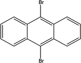
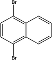
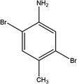
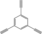
Here we examine a number of different CMP materials, all prepared via a palladium-catalysed Sonogashira–Hagihara cross-coupling reaction of 1,3,5-triethynylbenzene (TEB) with an aromatic dibromo monomer (DBM). The DBMs studied here are given in Table 1. A generic reaction scheme for this synthesis is given in Fig. 1. These networks, first synthesised experimentally by Dawson et al.,7 were prepared in a number of solvents: N,N-dimethylformamide (DMF), toluene, tetrahydrofuran (THF), and 1,4-dioxane, and demonstrate vastly different microporous surface areas depending on the reaction solvent chosen (Table S1, ESI†). Toluene, the initial choice of reaction solvent to prepare CMPs with, has since been replaced by DMF due to its general ability to yield CMP frameworks with greater BET surface areas than those prepared in toluene; a factor that is believed to arise due to the increased degree of microporosity present in these networks.
 | ||
| Fig. 1 The preparation of the CMP networks formed via a palladium-catalysed Sonogashira–Hagihara reaction of 1,3,5-triethynylbenzene with an aromatic DBM. | ||
Despite this knowledge, there has not yet been a definitive explanation for why this is the case, however, an understanding of which solvent would yield a particular CMP network with the highest surface area possible would be advantageous, as this would reduce the necessity for solvent screening processes, which prove expensive here due to the palladium catalyst used.
Whilst it is known that the porosities of CMP frameworks differ when they are prepared in different solvents, we do not yet know precisely why this is the case. One theory as to why different porosity properties are observed for different reaction solvents is the miscibility of the reactants with the solvent. This can be quantified by taking the polarity index of each solvent (a standard measure of how polar it is relative to the other solvent choices),8 and plotting this against the microporous surface area of the CMP network when synthesised using that solvent.
The four solvents used by Dawson et al. show a range of polarity indices going from the least polar solvent, toluene, at 2.4 to the most polar solvent, DMF, at 6.4. 1,4-Dioxane and THF are of intermediate polarity, with polarity indices of 4.0 and 4.8, respectively (Table S2, ESI†).8
When plotting the microporous surface areas of the CMPs studied here (Table S1, ESI†) against the solvent polarity indices in each case, it can be seen that a number of different trends occur. We hypothesise that these different trends arise due to the miscibility of the respective monomers resulting from the dipole moment of each DBM relative to TEB (Table S3, ESI†) and the solvent.
To determine the miscibility of the system firstly the Mulliken dipole moments were calculated for each of the DBMs 1-11, and for TEB, using a geometry optimisation calculation using Gaussian 09 (Revision E.01). The model chemistry used was B3LYP/6-31G.9–12 B3LYP is a widely used exchange–correlation functional, and the 6-31G basis set is suitably large.13 We can then use this to determine the relative polarity of each DBM and based upon this postulate the miscibility of each system.
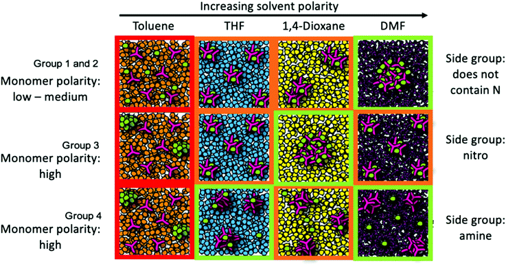
The DBMs can be grouped into a number of groups based upon their structure and polarity.7,8 The first grouping, Group 1, comprised of DBMs that do not contain nitrogen and have an absolute difference in their dipole moment with respect to TEB of <0.1 Debye, is plotted in Fig. 2a. It can be seen from Table S3 (ESI†) that this group has a very small absolute difference in the dipole moments of the two starting reagents (TEB and the DBM), meaning that the polarity of the two starting reagents is similar. The approximate trend seen in this group is an increase in the microporous surface area of the resultant CMPs as the solvent polarity increases, going from toluene to DMF. Fig. 3 summarises our postulated phase separation behaviour for TEB and the DBM in each solvent. In toluene both monomers are very soluble, leading to a fully miscible solution of all reactants in toluene. In contrast, in DMF, DBM and TEB are both immiscible, leading to co-phase separation of the reactants from the DMF solvent. THF and 1,4-dioxane act as intermediates here, as they have polarity indices in between those of DMF and toluene. We can infer that for this group the DMF acts as an anti-solvent, limiting the polymer formation process to regions of low solvation.
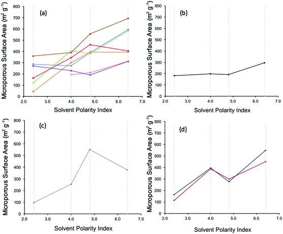 | ||
| Fig. 2 Plot of the microporous surface area of CMP networks against the polarity index of the reaction solvent.7,8 (a) CMP networks 1, 2, 3, 5, 6, 7, and 8 key: CMP-1 – blue, CMP-2 – orange, CMP-3 – pink, CMP-5 – purple, CMP-6 – green, CMP-7 – red, CMP-8 – brown. (b) CMP network 4 (c) CMP network 9 (d) CMP networks 10–11 against the polarity index of the reaction solvent.7,8 Key: CMP-10 – burgundy (dark red), CMP-11 – dark blue. Solvent polarity indices: DMF – 6.4, 1,4-dioxane – 4.8, THF – 4.0, toluene – 2.4 (shown as grey dashed lines on the graph for clarity). | ||
DBM-4 is plotted in its own group, Group 2, as it does not fit into any of the others due to DBM-4 not containing nitrogen groups, whilst there being a dipole moment between the two monomers of >0.1 Debye (0.7043 Debye). However, DBM-4 is quite aromatic, so can be approximated as following the same trend as the monomers in Group 1, showing an increasing surface area of CMP-4 with increasing polarity index, as seen in Fig. 2b.
Group 3 consists of DBM-9 which has a high dipole moment due to the nitro group (–NO2) attached. Fig. 3 summarises our postulated phase separation behaviour for TEB and the DBM in each solvent. CMP-9 shows an increase in microporous surface area with increasing solvent polarity index (Fig. 2c) with a peak at polarity index 4.8 (1,4-dioxane) and subsequently dropping at a polarity index of 6.4 (DMF). DBM-9 is not miscible in 1,4-dioxane and toluene, and partially miscible in THF and DMF. In toluene, this leads to phase separation of the DBM. In 1,4-dioxane, both DBM-9 and TEB are immiscible leading to co-phase separation. Similarly, to Group 1 and Group 2, 1,4-dioxane is acting as an anti-solvent limiting the polymer formation process to regions of low solvation. For CMP-9 synthesised in THF and DMF, TEB is less soluble than it is in toluene, and DBM-9 is more soluble than it is in toluene leading to partial phase separation resulting in intermediate surface areas.
For Group 4, consisting of DBM-10 and DBM-11 (Fig. 2d), an increase in microporous surface area of the respective CMPs with increasing solvent polarity index is observed with an increase at 4.0 (THF) followed by a drop at 4.8 (1,4-dioxane) and a subsequent increase at 6.4 (DMF). Fig. 3 summarises our postulated phase separation behaviour for TEB and the DBM in each solvent. CMP-10 and CMP-11 show their lowest microporous surface areas when prepared in toluene, as whilst TEB is soluble in this solvent, DBM-10 and DBM-11 are not, leading to their phase separation. In THF and 1,4-dioxane, both DBMs are more soluble than in toluene, leading to partial co-phase separation with THF showing the largest co-phase separation. There is a sharp increase in the microporous surface area on preparing CMP-10 and CMP-11 in DMF. It would be expected that, as is seen for CMP-9, the microporous surface area of the resulting CMP would decrease on increasing the solvent polarity to that of DMF as TEB is not soluble in this solvent. This difference must therefore arise from the choice of nitrogen functional group on the DBM. DBM-10 and DBM-11 may be able to interact with solvents that contain oxygen via hydrogen bonding between the DBM amine group and the solvent oxygen. DMF is known to form cluster structures that we can postulate are able to template the CMP network formation via H-bonding with the DBM leading to a higher surface area.14
From assessing the overall postulated phase separation behaviour shown in Fig. 3, we can draw some general rules:
(1) Each group must be taken into consideration individually to rationalise the behaviour.
(2) The highest surface area of the CMP network for each group results from co-phase separation of the reactants (except for when hydrogen bonding between solvent and reactants is possible). This is observed for Group 1 and 3 in DMF, Group 3 in 1,4-dioxane, and (ignoring DMF) in THF for Group 4.
(3) Similarly, the lowest surface areas result when the TEB and the DBM are kept fully apart either by phase separation or by full miscibility.
(4) Interaction between the solvent and the reactants can influence the surface area of the resultant polymer, as is observed for Group 4 in DMF.
Conclusions
In summary, we have rationalised the trends observed on preparing a number of conjugated microporous polymers using different reaction solvents, demonstrating a clear link between the miscibility of the reactants within the solvent used, the resultant phase separation behaviour, and the microporous surface area of the resulting polymer framework. The general rules that we have devised could potentially be applied to other amorphous hyper cross linked porous materials. This type of analysis could be adapted in the future to aid in the materials design of novel CMPs for energy storage with even higher surface areas and micropore volumes.Conflicts of interest
There are no conflicts to declare.Notes and references
- J.-X. Jiang, F. Su, A. Trewin, C. D. Wood, N. L. Campbell, H. Niu, C. Dickinson, A. Y. Ganin, M. J. Rosseinsky, Y. Z. Khimyak and A. I. Cooper, Angew. Chem., Int. Ed., 2007, 46, 8574–8578 Search PubMed.
- R. Dawson and A. Trewin, Porous Polymers: Design, Synthesis and Applications, 2015, pp. 155–185 Search PubMed.
- Y. Xu, S. Jin, H. Xu, A. Nagai and D. Jiang, Chem. Soc. Rev., 2013, 42, 8012–8031 Search PubMed.
- S. Das, P. Heasman, T. Ben and S. Qiu, Chem. Rev., 2017, 117, 1515–1563 Search PubMed.
- P. Fayon, J. M. H. Thomas and A. Trewin, J. Phys. Chem. C, 2016, 120, 25880–25891 Search PubMed.
- Z. Zhao, S. Das, G. Xing, P. Fayon, P. Heasman, M. Jay, S. Bailey, C. Lambert, H. Yamada, T. Wakihara, A. Trewin, T. Ben, S. Qiu and V. Valtchev, Angew. Chem., Int. Ed., 2018, 57, 11952–11956 Search PubMed.
- R. Dawson, A. Laybourn, Y. Z. Khimyak, D. J. Adams and A. I. Cooper, Macromolecules, 2010, 43, 8524–8530 Search PubMed.
- L. R. Snyder, J. Chromatogr., 1978, 92, 223–234 Search PubMed.
- A. D. Becke, Phys. Rev. A: At., Mol., Opt. Phys., 1988, 38, 3098–3100 Search PubMed.
- A. D. Becke, J. Chem. Phys., 1993, 98, 5648–5652 Search PubMed.
- C. Lee, W. Yang and R. G. Parr, Phys. Rev. B: Condens. Matter Mater. Phys., 1988, 37, 785–789 Search PubMed.
- R. Ditchfield, W. J. Hehre and J. A. Pople, J. Chem. Phys., 1971, 54, 724 Search PubMed.
- R. S. Mulliken, J. Chem. Phys., 1955, 23, 1833 Search PubMed.
- J. M. H. Thomas and A. Trewin, J. Phys. Chem. C, 2014, 118, 19712–19722 Search PubMed.
Footnote |
| † Electronic supplementary information (ESI) available: Catalytic mechanism, solvent structure, individual plots of solvent polarity against surface area for each CMP system. See DOI: 10.1039/d0cp03539d |
| This journal is © the Owner Societies 2020 |


