 Open Access Article
Creative Commons Attribution 3.0 Unported Licence
High-throughput screening of metal–organic frameworks for kinetic separation of propane and propene†
Yohanes
Pramudya‡
 a,
Satyanarayana
Bonakala
a,
Dmytro
Antypov
a,
Satyanarayana
Bonakala
a,
Dmytro
Antypov
 a,
Prashant M.
Bhatt
b,
Aleksander
Shkurenko
 b,
Mohamed
Eddaoudi
 b,
Matthew J.
Rosseinsky
 a and
Matthew S.
Dyer
 *a
*a
aDepartment of Chemistry, University of Liverpool, Liverpool L69 7ZD, UK. E-mail: msd30@liverpool.ac.uk
bKing Abdullah University of Science and Technology (KAUST), Physical Sciences and Engineering Division, AMPM Center, Functional Materials Design, Discovery and Development Research Group (FMD3), Thuwal, Saudi Arabia
First published on 6th October 2020
Abstract
We apply molecular simulations to screen a database of reported metal–organic framework structures from the computation-ready, experimental (CoRE) MOF database to identify materials potentially capable of separating propane and propene by diffusion. We report a screening workflow that uses descriptor analysis, conventional molecular dynamics (MD), and Nudged Elastic Band (NEB) energy barrier calculations at both classical force field and Density Functional Theory (DFT) levels. For the first time, the effects of framework flexibility on guest transport properties were fully considered in a screening process and led to the identification of candidate MOFs. The hits identified by this proof-of-concept workflow include ZIF-8 and ZIF-67 previously shown to have large differences in propane and propene diffusivities as well as two other materials that have not been tested experimentally yet. This work emphasises the importance of taking into account framework flexibility when studying guest transport in porous materials, demonstrates the potential of the data-driven identification of high-performance materials and highlights the ways of improving the predictive power of the screening workflow.
Introduction
In the petrochemical industry, separating olefins from paraffins by cryogenic distillation is an important but energy demanding process.1–4 Alternative methods are required to lower the energy consumption for key separations such as ethene/ethane and propene/propane separations.5–9 Using porous materials such as metal organic frameworks (MOFs) is one of the most promising paths because of the wide range of structures with different properties that can be explored.10–18 In fact, with over 90![[thin space (1/6-em)]](https://www.rsc.org/images/entities/char_2009.gif) 000 thousand MOFs reported to date in the Cambridge Structural Database (CSD),19 it is impractical to test all these materials for any given separation experimentally. There might be many known materials that have high performance for separations for which they have never been tested. This is an opportunity for computational chemistry to assess the performance of these materials in silico and identify best candidates for future experimental testing.
000 thousand MOFs reported to date in the Cambridge Structural Database (CSD),19 it is impractical to test all these materials for any given separation experimentally. There might be many known materials that have high performance for separations for which they have never been tested. This is an opportunity for computational chemistry to assess the performance of these materials in silico and identify best candidates for future experimental testing.
In this work, we focus on kinetic separation of propane and propene and assess the MOF materials present in the Computation-Ready, Experimental (CoRE) MOFs database that includes experimental guest-free structures of more than 4700 three-dimensional non-disordered MOFs.20 This database provides a starting point for screening calculations. It was used in a number of separation studies21–28 and was recently updated to include over 14![[thin space (1/6-em)]](https://www.rsc.org/images/entities/char_2009.gif) 000 structures.29
000 structures.29
The early computational studies21–25 of gas adsorption and separation using the CoRE MOF database were performed for rigid frameworks and were focused on calculating static thermodynamic properties like adsorption energies, Henry's coefficients and adsorption isotherms. These properties provide a measure of guest-framework interactions and can guide the selection and design of adsorbents for applications such as powder beds. However, the kinetic properties of gases are also relevant for designing molecular sieves for filtering applications. That is why more recent studies,26,27 also based on the original CoRE MOF database, included molecular dynamics (MD) calculations of self-diffusion coefficient of guest molecules in rigid frameworks. There are two shortcomings to this approach. First, treating the framework as rigid does not allow the pore dimensions to change due to thermal fluctuation or because of the interaction with the guest. Second, the random thermal movement of the guest molecule can only access relatively low energy barriers and more advanced computational methods that bias the guest trajectory are required to assess experimentally relevant diffusion barriers.30 These methods include metadynamics,31 adaptive biasing force32 and umbrella samplings33,34 at a finite temperature while the nudged elastic band (NEB) method35,36 allows for a relatively quick identification of the minimum energy path between two local minima.
The computer simulation studies that use flexible framework models combined with advanced computational tools show that taking framework flexibility into account is important to produce guest diffusivities observed experimentally.37 In particular, Verploegh et al. showed that the flexible window aperture in ZIF-8 framework has a large effect on the diffusion of gases, including propane and propene, when their molecular sizes are comparable or smaller than the average window size, ultimately affecting the calculated diffusion free energy barriers.33 These umbrella sampling calculations rely on predefining the reaction coordinate along the diffusion path through the pore window and can make accurate predictions when dedicated force field models are used.38 Witman et al. conducted the first set of screening calculations using UFF-fix-metal (UFF-FM) force field to describe the flexibility of the structures from CoRE MOF database and its effect on the adsorptive separation of Xe/Kr mixtures.28 To the best of our knowledge, there have been no large-scale screening studies of diffusion barriers in MOFs for any guest molecules and our work is the first attempt to do so.
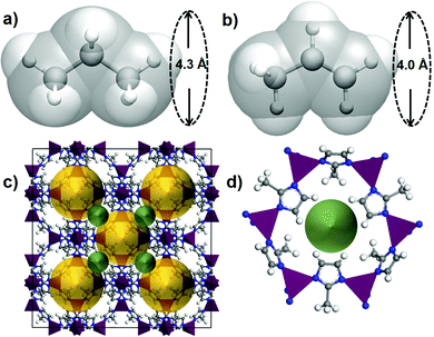
The small difference in size and shape of propane and propene (Fig. 1) makes it difficult to separate them by a sieving mechanism. The most often quoted values for kinetic diameters are 4.3 Å propane and 4.0 Å for propene,39 while some reports suggest using a smaller value of 4.2 Å for propane.37
There are several examples of MOFs that have been shown experimentally to have distinct kinetics for propane and propene. The examples include ZIF-837 (3.4 Å), ZIF-6740 (3.3 Å) that are present in the CoRE MOF database and other materials that were reported more recently Zn(ox)0.5(trz)10 (2.9 Å) and Zn(ox)0.5(atrz)10 (2.6 Å), ELM-1241 (4.0 Å) and KAUST-712 (2.7 Å) with the number in brackets indicating the pore window diameter. It is evident that in all cases, the size or the pore window is similar or smaller than the size of the guests and therefore the guest diffusion through such pore will require some flexibility of the pore window.
In the remainder of this paper, we present computational details of the screening workflow that assess diffusion barriers of propane and propene in MOFs where both the framework and guest are treated as flexible. We report the application of this workflow to CoRE MOF library of structures and discuss our findings.
Computational details
There are several challenges for high-throughput calculations of kinetic separations. First, similar to the screening for adsorptive separations, it is imperative to have a database of chemically correct host structures because missing or erroneous atoms will lead to incorrect identification of host properties. In this paper, we use the original CoRE MOF database (accessed form https://cmcp-group.github.io/CoRE-MOFs on 17/09/2017) without any further modification. Second, since the pore window flexibility is essential, we need a robust model to describe this flexibility for a chemically diverse set of MOFs present in the database. The UFF-FM force field was shown to reproduce the elastic properties of MOFs well and we use it to pre-screen the candidate structures before using more expensive but more accurate density functional theory (DFT) calculations. Third, we need an automated computational tool to calculate diffusion barriers. For this purpose we use the nudged elastic band (NEB) method35,36 that is often used to calculate ion mobility in solids but has also been applied to study molecular diffusion.42,43 Since the NEB method can calculate the barrier energy using either a force field or a DFT approach this will allow us to make a direct comparison between the UFF-FM and DFT data. The automatic generation of the NEB setup that involves the identification of a local minimum at each side of the pore window and the construction of the path between these two end points is one of the challenges we tackle in this paper.Scheme 1 summarises the details of our screening workflow that focuses on finding MOF structures that can separate propane and propene through sieving mechanism. At each step of the screening, we identify the most promising MOF structures to be considered at the next more computationally demanding step of screening, thus gradually reducing the number of candidates as indicated by the numbers of structures in Scheme 1.
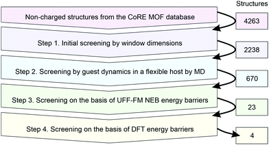 | ||
| Scheme 1 Schematic representation of the computational screening workflow with the numbers on the right indicating the number of structures that were passed to the next level of screening. | ||
Below we provide the details of the main four steps of the workflow.
Step 1. Simple geometric descriptors – pore and window size
For a binary gas mixture, a perfect sieve would allow the diffusion of one component through but completely block the other component. If both components can readily diffuse through the material, we would discard such material. We used Zeo++ to calculate the window size, also referred to as the pore limiting diameter (PLD) or the largest free sphere Df. After excluding 501 MOFs marked as charged from the list of 4764 MOF structures present in CoRE MOF database we discarded MOFs with window diameter smaller than 2.5 Å and greater than 4.3 Å. This simple descriptor-based screening based on rigid framework geometries and using spherical probes reduced the number of options from 4263 to 2238. For the next step of the screening workflow, we used flexible framework models and atomistically accurate models of the guests.Step 2. Molecular dynamics simulations of guest diffusion
To discard the systems that allow propane diffusion even on a short time scale, we used large-scale atomic/molecular massively parallel simulator (LAMMPS) to perform 5 ns conventional molecular dynamics (MD) simulation in the NVT ensemble. An elevated temperature of T = 400 K was used to accelerate the dynamics of guest diffusion in a flexible host while keeping the simulations numerically stable. A single propane or propene guest molecule was added in the middle of the pore cavity and the LAMMPS input files were generated from these CoRE MOF structures with the guest added using the lammps_interface code (accessed on https://github.com/peteboyd/lammps_interface on 06/10/2017) developed by Boyd et al.44 The electrostatic interactions were not included since both propane and propene are non-polar molecules and the effect of the electrostatics on diffusion barrier was expected to be relatively small.45,46 In our MD simulations, all chemical bonds, angles and dihedrals were treated as flexible using either harmonic potentials or hybrid Fourier cosine/periodic potentials according to the UFF-FM force-field. This force field was previously used to study adsorption of Xe/Kr mixtures in flexible MOFs.28 In our tests it performed similarly to the UFF4MOF47 but had a wider coverage of metal atom chemistries.Step 3. Classical force field level of NEB
We performed classical force-field-based NEB in LAMMPS by using the same UFF-FM potentials as those used in our MD simulations. However, the main challenge to set up NEB calculations for each MOF was to automatically generate the end points of the NEB paths. These are two host + guest structures with the guest molecule residing on either side of the pore window. To assist the location of the pore window, the Zeo++ developers modified the Zeo++ code so it can identify a Voronoi node that was close to the narrowest part of the channel. We found that in approximately 80% cases, the algorithm was able to identify two points, one on each side of the window, and in 20% cases when the pores shape was complex, these two points either coincided or belonged to two different windows.For the cases when two distinct Voronoi nodes were identified near the same window, we used the vector connecting these two points as the direction of the channel and developed a code to orient and place the guest molecules at the opposite sides of the window. Specifically, four orientations (90° rotations) of the guest molecule located at one of three separations from the identified Voronoi nodes (1 Å, 2 Å, and 3 Å) were used. Thus we setup 12 NEB paths for propane, 12 NEB paths for propene where the CH3 group passes through the window first, and 12 NEB paths where the propene CH2 group passes through the window first. Each NEB path consisted of 32 replicas, which were created by placing the guest molecule along the linear path connecting the two NEB end points. Following the standard partitioning scheme recommended in LAMMPS, in each replica, the atoms were partitioned into NEB-atoms (the guest) and non-NEB-atoms (the framework). Only the NEB-atoms were connected by inter-replica spring and felt the forces from inter-replica atoms. Conceptually, the framework atoms provided a background potential for the guest atoms. The energy barrier for each MOF was calculated as the difference between the lowest maxima and the lowest minima from the entire set of tried NEB paths.
For quality control, we used two NEB setups: the first setup was better in identifying the lowest energy configurations but sometimes produced an unphysical diffusion path, while the second setup was better in finding the path through the pore window but worse in finding adsorption sites. In the first setup, we performed energy minimisation of the NEB end points before building the path that connects them. The stopping criterion for force was 0.1 kcal mol−1 Å−1 (maximum force on each atom), and the Hessian-free truncated Newton algorithm was used in LAMMPS. Once the two end points were optimized, the NEB path was created as a straight line between them. In some cases, when the minimized end points were reached, the guest molecules moved far from their initial position at the centre of the channel axis and the straight-line NEB path that connected the two end points would no longer pass through the pore window but through the pore wall next to the window. In other cases, after the energy minimisation both NEB end points could end up in the same pore cavity, not at the opposite sides of the window. Therefore, these NEB paths would not pass the narrowest part of the pore channel and would return a low energy barrier for moving the guest within a single pore cavity.
In the second setup, we created the NEB paths between the end points without their energy minimization. These end points configurations were optimized at the same time as when the NEB calculation was performed. Thus the second setup conceptually prevented the NEB path from hitting the pore wall. It also decreased the chances of both NEB end points moving to the same pore cavity. However, if these problems did not occur in the 1st setup, the energy barriers calculated using the 1st NEB setup were more accurate than those calculated using the 2nd NEB setup because the 1st NEB setup provided a better identification of adsorption sites – the minima found after the initial energy minimization in the 1st NEB setup were typically lower in energy than the end points in the 2nd NEB set up. We shortlisted all MOFs identified by the 1st NEB setup if the diffusion barriers identified by the 2nd NEB setup were within 30% difference and the propene diffusion barrier was not prohibitively high, i.e. less than 100 kJ mol−1.
In all force field NEB calculations damped dynamics with a time step was 1 fs was used to stably optimise the system. The force tolerance for the NEB calculation was 0.5 kcal mol−1 Å−1, with a spring constant of 1.0 kcal Å−2.
Step 4. Density functional theory level of NEB
We performed the density functional theory (DFT) level NEB in Vienna Ab initio Simulation Package (VASP 5.4.4)48 for 23 candidates selected based on the energy barriers calculated by UFF-FM. All DFT calculations were performed with projector augmented wave (PAW)49 pseudopotentials using periodic boundary conditions, and the optB86b-vdW functional which includes van der Waals correction and in general gave minimized structures close to experimental structures.50We allowed the volume and the shape of the primitive cell to change during the conjugate gradient structure optimisation, with a plane-wave energy cut-off 600 eV and stopping optimisation when the energy of subsequent ionic steps differed by less than 10−6 eV. Gaussian smearing with a width of 0.1 eV was used. Most MOFs had a relatively large unit cell with each dimension greater than 10 Å, thus a k-point grid of 2 × 2 × 2 with Γ point sampling was sufficient for these systems.
For the NEB DFT calculations, we set the force tolerance to 0.05 eV Å−1 and used quasi-Newton energy minimization with a NEB spring constant of 5 eV Å−2, and the climbing image NEB method. The replicas along the NEB paths were generated spanning the entire unit cell in order to explore all possible local minima that may be found along the pore. The energy barrier was defined as the difference between the highest and the lowest energy along the calculated minimum energy path. The number of replicas in each NEB path varied between 8 and 25 replicas, depending on the length and the complexity of the path and the initial distance between the guest molecules in each replica was a maximum of 1 Å.
Results and discussion
Molecular dynamics simulations
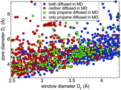
From the 2238 shortlisted MOF structures with window size less than 4.3 Å we were able to perform 5 ns MD simulations of guest diffusion at 400 K for 1440 MOFs. The remaining 35% were unsuccessful either due to the errors incorporated in the input structures or due to misidentification of chemical bonds when converting CoRE MOF entries to LAMMPS input files. The results of the successful MD simulations are shown in Fig. 2. Each circle in Fig. 2 represents a MOF structure with its window diameter plotted along the x-axis and its pore diameter plotted along the y-axis while the colour of the circle represents the outcome of the single MD simulation. We considered the guest molecule being able to readily diffuse through the MOF if it travelled more than the size of the unit cell in at least one direction (x, y, or z) during the 5 ns MD simulation. Based on this criterion, we observed that both gases diffused to the neighbouring unit cell within 5 ns in 743 MOFs (blue circles), only propene diffused in 224 MOFs (green circles), only propane diffused in 27 MOFs (orange squares), and both guests remained in the same unit cell in 446 MOFs (red circles).The distribution of coloured circles in Fig. 2 correlates well with the MOF window sizes. Most blue circles (both guests diffused) correspond to MOFs with a wide pore window (Df > 3.8 Å), and most red circles (neither guest diffused) correspond to MOFs with a narrow pore window (Df < 3.0 Å). MOFs that only allowed propene diffusion (green circles) are concentrated in the window range of 3.5–3.8 Å. Some MOFs in Fig. 2 appear to be outliers from the common trends. For example, there are several MOFs with wide pores (Df > 4.0 Å) that were deemed to block diffusion of one or both guests because the guest molecules were not able to find the window and pass though it during the short simulation time of 5 ns. The stochastic nature of guest diffusion was also the main reason for some systems (orange squares) showing propane diffusion but not propene. There are also some blue circles for MOFs with a narrow pore window (Df < 3 Å). For most of these MOFs the shape of the pore window is not circular and Df corresponds to the smallest limiting dimension while the pore is wider in the orthogonal direction. For some of the outliers it was found that the pore structure changed significantly because either UFF-FM force field did not provide an accurate description or the input structures from CoRE MOF database had missing atoms or erroneous atoms. For example, there are seven structures of ZIF-8 present in CoRE MOF database (those with CSD reference codes of OFERUN02, OFERUN03, FAWCEN, FAWCEN01, FAWCEN02, FAWCEN03, KAMZUV) and only one of them (OFERUN03) contains a correct number of hydrogen atoms.
For the next step of screening, we consider only the 670 MOFs that did not show propane diffusion at the short time scale of the MD simulation but might still allow its diffusion at the experimental time scales. For example, driven by random thermal motion, neither propane nor propene passed through the pore window of ZIF-8 in our 5 ns MD simulations, whereas extending simulation time to 50 ns showed a single hopping event for propene. That is why Nudged Elastic Band calculations were used to directly assess experimentally relevant diffusion barriers at the next step of the workflow.
Nudged elastic band (NEB)
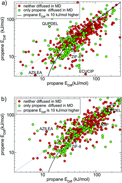
First, in cases when the NEB end points were incorrectly assigned either to the same pore cavity or to two different channels in approximately 20% of the MOFs, the calculated diffusion barriers were respectively very low (∼10 kJ mol−1) or very high (∼1000 kJ mol−1) and did not correlate with the results of MD simulations. Second, in some cases when the NEB end points were initially located at opposite sides of the window, they moved during the initial energy optimisation (1st NEB setup) or during the NEB calculation (2nd NEB setup) and ended up in the same pore cavity. This happened more often in the 1st NEB setup than the 2nd and typically resulted in a low diffusion energy barrier. The structures with CSD reference codes ECUCIP, QUPDEL and AZILEA, shown in Fig. 3a and b, are the examples of MOFs for which the whole NEB trajectory (respectively for propene, propane and both guests) ended up in the same pore cavity when we used the 1st NEB setup, as indicated by a low Ediff, but not in the 2nd NEB setup. Third, upon energy minimisation, some structures experienced large displacements of framework atoms due to the force field limitations. This often led to the closure of the pore window and a relatively high diffusion barrier.
Fig. 4 shows all MOFs selected from Fig. 3(a) that consistently (within 30% difference) reproduce diffusion barriers for both guests in the 1st and 2nd NEB setups and have a calculated diffusion barrier for propene less than 100 kJ mol−1. Among these 164 MOFs, 116 MOFs (all points under the solid black line in Fig. 4) have energy barriers for propane at least 10 kJ mol−1 higher than that for propene. For these MOFs the NEB calculations are mostly consistent with the MD simulations, as most green points in Fig. 4 correspond to low diffusion barriers for propene and most red points correspond to high diffusion barriers for propene.
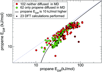 | ||
| Fig. 4 164 MOFs from the 1st NEB setup (coloured either red or green as in Fig. 3a) that had consistent diffusion energy barriers in both 1st NEB and 2nd NEB setups. There are 115 candidate MOFs under the black line the energy barrier for propane is at least 10 kJ mol−1 higher than for propene, 23 of which selected for DFT studies are marked by a black dot. | ||
We carefully inspected the 116 shortlisted structures to remove duplicates and chemically incorrect structures. From the list of 82 chemically correct and unique MOFs we selected a representative subset of 23 MOFs (marked by a black dot in Fig. 4) that had fewer than 400 atoms per unit cell and did not contain elements heavier than caesium except IFEPIT (Lanthanide MOF) for case study purposes.
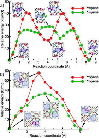
Fig. 6 shows the minimum energy paths calculated using DFT NEB method for propane (the red circles) and propene (the green circles) for the two new hits, OPENIH and IJENER, that were identified to be most similar to ZIF-8 and ZIF-67. To better visualize the change in pore shape during guest transport in both MOFs, the snapshots of the structures at minimum and maximum energy regions are shown in Fig. 6 with the free pore volume shown in light blue. Both guest molecules have energy minima at the cavity regions at the ends of the NEB path whereas the barriers are observed in the window region. In both MOFs, propene experiences a lower diffusion energy barrier than propane. The clear difference between the two MOFs is that in structure OPENIH (Fig. 6a) the diffusion path is complex and contains additional minima corresponding to the guest residing in the pore window, while structure IJENER (Fig. 6b) has a single barrier for either guest. While window dimeter is smaller for IJENER (2.58 Å) than that for OPENIH (3.18 Å) in the absence of the guests, it is evident that IJENER has a more flexible window as it experiences a larger size change (from 2.58 Å to 3.03 Å for propene and to 3.10 Å for propane) than the window in OPENIH (from 3.18 Å to 3.33 Å for propene and to 3.39 Å for propane). In IJENER, the size of the window is controlled by the position of the methyl groups protruding into the 3-dimensional channel and bonded to sulphur atoms that in turn make two bonds with the framework and therefore are relatively mobile (Fig. 6b). In contrast, the 1-dimensional channel in OPENIH is composed from π-stacked 4,4′-bpt linkers and the mechanism for window opening to allow guest transport is via small displacements of the individual linkers within the stack. Both mechanisms are different from window opening in ZIFs where it is controlled by the tilt of the imidazolate-based linkers forming the window (Fig. 1d). The example of OPENIH, IJENER and ZIF MOFs reinforces the importance of using energetic considerations and a flexible host model to assess guest transport properties rather than solely relying on the average pore dimensions observed in diffraction experiments.
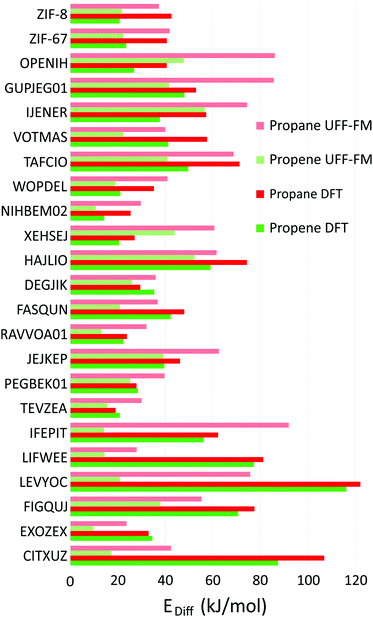
The correlations between UFF-FM force field and DFT energy barriers is shown in Fig. 7. The UFF-FM force field was exceptionally good at estimating energy barriers of Zeolitic Imidazolate Framework (ZIF) with pyrazole linkers in ZIF-8 (Zn-pyrazole) and ZIF-67 (Co-pyrazole). The energy barriers from UFF-FM and DFT were in line with previous computational studies and experiments of ZIF-855 and ZIF-67.6,30 The force field energy barriers for HAJLIO (Fe-pyrazole) and DEGJIK (Cu-pyridyltetrazole) were also close to those in DFT calculations. In general, the UFF-FM force field was able to predict the energy barriers well for MOFs with short carboxylate, pyrazole, pyridine, bipyridine linkers and Secondary Building Unit (SBU) containing Zn, Cu, Co, and Fe metals (Fig. 8). The energy barriers calculated with the UFF-FM force field were within ±40% of the DFT data for propane in FASQUN, HAJLIO, ZIF-8, ZIF-67, WOPDEL, RAVVOA, NIHBEM, DEGJIK, JEJKEP, PEGBEK01, and TEVZEA.
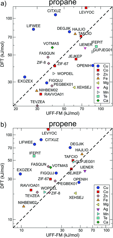 | ||
| Fig. 7 The correlation between diffusion energy barriers calculated for (a) propane and (b) propene using the UFF-FM force field and DFT methods. The data points are the same as those in Fig. 5 arranged according to the different metals in the SBU. | ||
We found that the UFF-FM force field did not work well with heavy atoms compounds, such as Te, Re, Gd in IFEPIT for which it significantly overestimated the energy barriers for propane and underestimated for propene. Four out of 23 MOFs shortlisted for DFT (LIFWEE, LEVYOC, CITXUZ and EXOZEX) had a water molecule coordinated to the metal ion in the reported experimental structures that was removed in the CoRE MOF database leaving an open metal site behind. With the exception of EXOZEX structure, three out of these four MOFs show large diffusion barriers in DFT due to strong guest–host interaction not captured in the UFF-FM calculations. For EXOZEX and FIGQUJ containing flexible linkers (with respectively two and three sequential sp3 carbon atoms), UFF-FM underestimated the energy barriers because of relatively low energy cost in UFF-FM to fold these linkers. The calculated energy barriers of alkaline-earth metals (Sr, Ca) based MOF, CSD reference code VOTMAS in force field based NEB is only half that of DFT. Alkali and alkaline-earth compounds have stronger ionic electrostatics effects than transition metals compounds56 and the difference can be observed even with non-polar molecules. For example, for the four structures with the same diamond network formed by formate linker with different metals (Co in RAVVOA,57 Fe in NIHBEM,58 Zn in TEVZEA,59 and Mg in XEHSEJ60), only for XEHSEJ with Mg, an alkaline-earth metal, we found that the UFF-FM underestimated the energy barrier by more than a factor of two compared to DFT. In most cases, UFF-FM underestimated propene energy barriers to a greater extent than those for propane when compared with DFT: only 3 out of 23 MOFs, the UFF-FM energy barriers for propene were significantly higher than DFT (Fig. 7b).
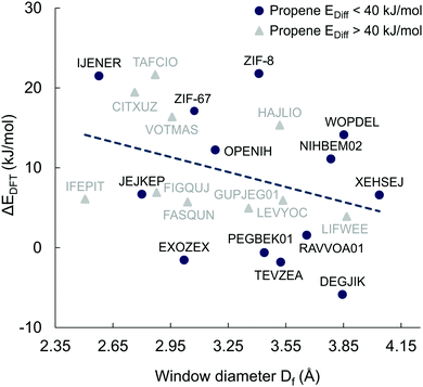
Fig. 8 shows the energy barrier difference between propane and propene (ΔEDFT = Epropane − Epropene) as a function of window sizes for the 23 MOFs shortlisted for DFT calculations. A large value of ΔEDFT is indicative of a stronger separation ability but cannot be used a single figure of merit as it does not take into account the absolute values of the diffusion barriers. For example, the calculated diffusion barrier for propene in CITXUZ is 87.5 kJ mol−1 which is too high for this material to be recommended as a good candidate for separation. The dashed line of best fit in Fig. 8 shows a weak correlation between ΔEDFT and the window size with a large scatter of the data points around the line. This indicates that knowing only the window size of a particular MOF is insufficient to predict the difference in diffusion barriers, ΔEDFT. One needs to account for the flexibility of the framework and the details of guest–host interactions to calculate the diffusion barriers of the guest molecules. This validates our screening process that was carried out by considering flexible models of hosts and guests.
Conclusions
We have developed a workflow for high-throughput screening of MOFs for separating propane and propene by diffusion. In the heart of the workflow is the automated setup that identifies the position of the narrowest part of the pore channel, the window, and performs nudged elastic band calculations to identify the diffusion barrier for each guest molecule through this window. We computationally identified two materials, ZIF-8 and ZIF-67, that were previously shown to have large differences in propane and propene diffusivities as well as two other materials (CSD reference codes OPENIH and IJENER) that have not been tested experimentally for separating propane and propene yet.We found that UFF-FM force field, compared to DFT method, was able to estimate diffusion energy barriers well for MOFs containing Fe, Cu, Co, and Zn metals in the SBUs and short pyrazole, carboxylate, pyridine, bipyridine linkers. The UFF-FM was not able to estimate the barriers energy for MOFs with long flexible linkers such as those containing two or more sequential sp3 carbon atoms. While this work presents the first attempt to calculate diffusion barriers in a high-throughput screening approach, its predictive power can be improved by (1) improving the quality of the materials database, (2) improving the accuracy of pore window identification, (3) improving the accuracy of the force field calculations and (4) using computational biasing tools that include entropic effects.
Conflicts of interest
Y. P., S. B., D. A., M. S. D., and M. J. R. declare that there are no conflicts of financial interest.Acknowledgements
This publication is based upon work supported by the King Abdullah University of Science and Technology (KAUST) Office of Sponsored Research (OSR) under award number OSR-2016-RPP-3273. The calculations were performed on the HPC resources of the Supercomputing Laboratory at KAUST. We would like to thank Peter Boyd for making the python LAMMPS interface available for open access and Maciec Haranczyk for modifying Zeo++ package to locate the narrowest part of the pore. D. A. thanks the Leverhulme Trust for funding via the Leverhulme Research Centre for Functional Materials Design.Notes and references
- K. Wang, Science, 2001, 291, 106–109 CrossRef CAS.
- S. Zhou, Y. Wei, L. Li, Y. Duan, Q. Hou, L. Zhang, L.-X. Ding, J. Xue, H. Wang and J. Caro, Sci. Adv., 2018, 4, eaau1393 CrossRef CAS.
- J. E. Bachman, Z. P. Smith, T. Li, T. Xu and J. R. Long, Nat. Mater., 2016, 15, 845 CrossRef CAS.
- J.-R. Li, R. J. Kuppler and H.-C. Zhou, Chem. Soc. Rev., 2009, 38, 1477–1504 RSC.
- H. Jarvelin and J. R. Fair, Ind. Eng. Chem. Res., 1993, 32, 2201–2207 CrossRef CAS.
- R. Sharon, R. Jubin and C. Bill, Materials for Separation Technologies. Energy and Emission Reduction Opportunities, United States, 2005 Search PubMed.
- M. Hartmann, S. Kunz, D. Himsl, O. Tangermann, S. Ernst and A. Wagener, Langmuir, 2008, 24, 8634–8642 CrossRef CAS.
- S. Bendt, M. Hovestadt, U. Böhme, C. Paula, M. Döpken, M. Hartmann and F. J. Keil, Eur. J. Inorg. Chem., 2016, 4440–4449 CrossRef CAS.
- M. Hartmann, U. Böhme, M. Hovestadt and C. Paula, Langmuir, 2015, 31, 12382–12389 CrossRef CAS.
- J. Peng, H. Wang, D. H. Olson, Z. Li and J. Li, Chem. Commun., 2017, 53, 9332–9335 RSC.
- A. F. P. Ferreira, J. C. Santos, M. G. Plaza, N. Lamia, J. M. Loureiro and A. E. Rodrigues, Chem. Eng. J., 2011, 167, 1–12 CrossRef CAS.
- A. Cadiau, K. Adil, P. M. Bhatt, Y. Belmabkhout and M. Eddaoudi, Science, 2016, 353, 137–140 CrossRef CAS.
- K. Li, D. H. Olson, J. Seidel, T. J. Emge, H. Gong, H. Zeng and J. Li, J. Am. Chem. Soc., 2009, 131, 10368–10369 CrossRef CAS.
- M. Hovestadt, S. Friebe, L. Helmich, M. Lange, J. Möllmer, R. Gläser, A. Mundstock and M. Hartmann, Molecules, 2018, 23, 889 CrossRef.
- Z. Bao, S. Alnemrat, L. Yu, I. Vasiliev, Q. Ren, X. Lu and S. Deng, Langmuir, 2011, 27, 13554–13562 CrossRef CAS.
- C. Y. Lee, Y.-S. Bae, N. C. Jeong, O. K. Farha, A. A. Sarjeant, C. L. Stern, P. Nickias, R. Q. Snurr, J. T. Hupp and S. T. Nguyen, J. Am. Chem. Soc., 2011, 133, 5228–5231 CrossRef CAS.
- H. Wang, X. Dong, V. Colombo, Q. Wang, Y. Liu, W. Liu, X.-L. Wang, X.-Y. Huang, D. M. Proserpio, A. Sironi, Y. Han and J. Li, Adv. Mater., 2018, 30, 1805088 CrossRef.
- J. van den Bergh, C. Gücüyener, E. A. Pidko, E. J. M. Hensen, J. Gascon and F. Kapteijn, Chem. – Eur. J., 2011, 17, 8832–8840 CrossRef CAS.
- P. Z. Moghadam, A. Li, S. B. Wiggin, A. Tao, A. G. P. Maloney, P. A. Wood, S. C. Ward and D. Fairen-Jimenez, Chem. Mater., 2017, 29, 2618–2625 CrossRef CAS.
- Y. G. Chung, J. Camp, M. Haranczyk, B. J. Sikora, W. Bury, V. Krungleviciute, T. Yildirim, O. K. Farha, D. S. Sholl and R. Q. Snurr, Chem. Mater., 2014, 26, 6185–6192 CrossRef CAS.
- B. C. Yeo, D. Kim, H. Kim and S. S. Han, J. Phys. Chem. C, 2016, 120, 24224–24230 CrossRef CAS.
- S. Li, Y. G. Chung and R. Q. Snurr, Langmuir, 2016, 32, 10368–10376 CrossRef CAS.
- C. Altintas, G. Avci, H. Daglar, A. Nemati Vesali Azar, S. Velioglu, I. Erucar and S. Keskin, ACS Appl. Mater. Interfaces, 2018, 10, 17257–17268 CrossRef CAS.
- D. Tang, Y. Wu, R. J. Verploegh and D. S. Sholl, ChemSusChem, 2018, 11, 1567–1575 CrossRef CAS.
- P. Z. Moghadam, T. Islamoglu, S. Goswami, J. Exley, M. Fantham, C. F. Kaminski, R. Q. Snurr, O. K. Farha and D. Fairen-Jimenez, Nat. Commun., 2018, 9, 1378 CrossRef.
- H. Daglar and S. Keskin, J. Phys. Chem. C, 2018, 122, 17347–17357 CrossRef CAS.
- S. Budhathoki, O. Ajayi, J. A. Steckel and C. E. Wilmer, Energy Environ. Sci., 2019, 12, 1255–1264 RSC.
- M. Witman, S. Ling, S. Jawahery, P. G. Boyd, M. Haranczyk, B. Slater and B. Smit, J. Am. Chem. Soc., 2017, 139, 5547–5557 CrossRef CAS.
- Y. G. Chung, E. Haldoupis, B. J. Bucior, M. Haranczyk, S. Lee, H. Zhang, K. D. Vogiatzis, M. Milisavljevic, S. Ling, J. S. Camp, B. Slater, J. I. Siepmann, D. S. Sholl and R. Q. Snurr, J. Chem. Eng. Data, 2019, 64, 5985–5998 CrossRef CAS.
- P. Krokidas, M. Castier and I. G. Economou, J. Phys. Chem. C, 2017, 121, 17999–18011 CrossRef CAS.
- A. Barducci, G. Bussi and M. Parrinello, Phys. Rev. Lett., 2008, 100, 20603 CrossRef.
- A. Hazra, S. Bonakala, K. K. Bejagam, S. Balasubramanian and T. K. Maji, Chem. – Eur. J., 2016, 22, 7792–7799 CrossRef CAS.
- R. J. Verploegh, S. Nair and D. S. Sholl, J. Am. Chem. Soc., 2015, 137, 15760–15771 CrossRef CAS.
- H. S. Hansen and P. H. Hünenberger, J. Comput. Chem., 2010, 31, 1–23 CrossRef CAS.
- G. Henkelman, B. P. Uberuaga and H. Jónsson, J. Chem. Phys., 2000, 113, 9901 CrossRef CAS.
- G. Henkelman and H. Jónsson, J. Chem. Phys., 2000, 113, 9978 CrossRef CAS.
- C. Zhang, R. P. Lively, K. Zhang, J. R. Johnson, O. Karvan and W. J. Koros, J. Phys. Chem. Lett., 2012, 3, 2130–2134 CrossRef CAS.
- R. J. Verploegh, A. Kulkarni, S. E. Boulfelfel, J. C. Haydak, D. Tang and D. S. Sholl, J. Phys. Chem. C, 2019, 123, 9153–9167 CrossRef CAS.
- J. H. Hirschfelder, C. F. Curtiss and R. B. Bird, Molecular theory of gases and liquids, Wiley, New York, 1954 Search PubMed.
- H. T. Kwon, H.-K. Jeong, A. S. Lee, H. S. An and J. S. Lee, J. Am. Chem. Soc., 2015, 137, 12304–12311 CrossRef CAS.
- L. Li, R.-B. Lin, X. Wang, W. Zhou, L. Jia, J. Li and B. Chen, Chem. Eng. J., 2018, 354, 977–982 CrossRef CAS.
- P. Canepa, N. Nijem, Y. J. Chabal and T. Thonhauser, Phys. Rev. Lett., 2013, 110, 026102 CrossRef.
- K. Tan, S. Zuluaga, E. Fuentes, E. C. Mattson, J.-F. Veyan, H. Wang, J. Li, T. Thonhauser and Y. J. Chabal, Nat. Commun., 2016, 7, 13871 CrossRef CAS.
- P. G. Boyd, S. M. Moosavi, M. Witman and B. Smit, J. Phys. Chem. Lett., 2017, 8, 357–363 CrossRef CAS.
- M. Gholami and S. Yeganegi, Mol. Simul., 2018, 44, 389–395 CrossRef CAS.
- M. Wehring, J. Gascon, D. Dubbeldam, F. Kapteijn, R. Q. Snurr and F. Stallmach, J. Phys. Chem. C, 2010, 114, 10527–10534 CrossRef CAS.
- D. E. Coupry, M. A. Addicoat and T. Heine, J. Chem. Theory Comput., 2016, 12, 5215–5225 CrossRef CAS.
- G. Kresse and J. Furthmüller, Phys. Rev. B: Condens. Matter Mater. Phys., 1996, 54, 11169–11186 CrossRef CAS.
- G. Kresse and D. Joubert, Phys. Rev. B: Condens. Matter Mater. Phys., 1999, 59, 1758–1775 CrossRef CAS.
- J. Klimeš, D. R. Bowler and A. Michaelides, Phys. Rev. B: Condens. Matter Mater. Phys., 2011, 83, 195131 CrossRef.
- D. Antypov, A. Shkurenko, P. M. Bhatt, Y. Belmabkhout, K. Adil, A. Cadiau, M. Suyetin, M. Eddaoudi, M. J. Rosseinsky and M. S. Dyer, Nat. Commun., 2020 Search PubMed , accepted.
- F.-P. Huang, J.-L. Tian, W. Gu and S.-P. Yan, Inorg. Chem. Commun., 2010, 13, 90–94 CrossRef CAS.
- X.-P. Zhou, Z. Xu, M. Zeller, A. D. Hunter, S. S.-Y. Chui, C.-M. Che and J. Lin, Inorg. Chem., 2010, 49, 7629–7631 CrossRef CAS.
- L. Zhang, K. Jiang, J. Zhang, J. Pei, K. Shao, Y. Cui, Y. Yang, B. Li, B. Chen and G. Qian, ACS Sustainable Chem. Eng., 2019, 7, 1667–1672 CrossRef CAS.
- B. Zheng, L. L. Wang, L. Du, Y. Pan, Z. Lai, K.-W. Huang and H. L. Du, Mater. Horiz., 2016, 3, 355–361 RSC.
- A. M. Allgeier, C. S. Slone, C. A. Mirkin, L. M. Liable-Sands, G. P. A. Yap and A. L. Rheingold, J. Am. Chem. Soc., 1997, 119, 550–559 CrossRef CAS.
- Z. Wang, B. Zhang, M. Kurmoo, M. A. Green, H. Fujiwara, T. Otsuka and H. Kobayashi, Inorg. Chem., 2005, 44, 1230–1237 CrossRef CAS.
- Z.-M. Wang, Y.-J. Zhang, T. Liu, M. Kurmoo and S. Gao, Adv. Funct. Mater., 2007, 17, 1523–1536 CrossRef CAS.
- Z. Wang, Y. Zhang, M. Kurmoo, T. Liu, S. Vilminot, B. Zhao and S. Gao, Aust. J. Chem., 2006, 59, 617 CrossRef CAS.
- J. Xu, V. V. Terskikh, Y. Chu, A. Zheng and Y. Huang, Chem. Mater., 2015, 27, 3306–3316 CrossRef CAS.
Footnotes |
| † Electronic supplementary information (ESI) available. See DOI: 10.1039/d0cp03790g |
| ‡ Current address: Institute of Nanotechnology, Karlsruhe Institute of Technology, Karlsruhe 76344, Germany. |
| This journal is © the Owner Societies 2020 |

