Highly efficient H2 production from H2S via a robust graphene-encapsulated metal catalyst†
Mo
Zhang‡
ab,
Jing
Guan‡
c,
Yunchuan
Tu
ab,
Shiming
Chen
 b,
Yong
Wang
ab,
Suheng
Wang
ab,
Liang
Yu
b,
Chao
Ma
d,
Dehui
Deng
*ab and
Xinhe
Bao
b,
Yong
Wang
ab,
Suheng
Wang
ab,
Liang
Yu
b,
Chao
Ma
d,
Dehui
Deng
*ab and
Xinhe
Bao
 b
b
aState Key Laboratory of Physical Chemistry of Solid Surfaces, Collaborative Innovation Center of Chemistry for Energy Materials (iChEM), College of Chemistry and Chemical Engineering, Xiamen University, Xiamen 361005, China
bState Key Laboratory of Catalysis, iChEM, Dalian Institute of Chemical Physics, Chinese Academy of Science, Zhongshan Road 457, Dalian 116023, China. E-mail: dhdeng@dicp.ac.cn
cSchool of Environmental & Municipal Engineering, Qingdao University of Technology, Qingdao 266033, China
dCenter for High Resolution Electron Microscopy, College of Materials Science and Engineering, Hunan University, Changsha 410082, China
First published on 23rd November 2019
Abstract
The electrocatalytic decomposition of the abundant and toxic H2S from industrial by-products is a promising energy conversion technology for H2 production and simultaneously removing this environmental pollutant. However, the development of such a technology has been hindered by the lack of low-cost, efficient and robust electrocatalysts. Herein, we reported a remarkable graphene-encapsulated metal catalyst, i.e., nitrogen-doped graphene encapsulating a non-precious CoNi nanoalloy as the anode for highly efficient electrocatalytic H2 production from H2S. This optimized catalyst could drive the anode reaction at an onset potential of 0.25 V, which was 1.24 V lower than that required for the water oxidation reaction, and delivered almost twice current density than that of Pt/C. Meanwhile, it exhibited approximately 98% H2 faradaic efficiency and maintained long-term durability for more than 500 h without any decay. The density functional theory calculations revealed that the CoNi and nitrogen dopants synergistically facilitated the formation of polysulfides on graphene's surfaces. Furthermore, a demo showed 1200 h stability for removing H2S impurities from industrial syngas to produce hydrogen by this graphene-encapsulated metal catalyst, demonstrating its great potential for hydrogen production toward sustainable energy applications.
Broader contextHydrogen sulfide is a toxic by-product of oil and gas production released in enormous quantities, and it is also a potential source of an important green energy carrier, namely, hydrogen gas. Based on the Claus process, the current industrial technology for removing H2S can only recover sulfur from H2S, while the hydrogen constituent is wasted as steam. The electrocatalytic decomposition of H2S, which produces hydrogen at the cathode and recycles sulfur at the anode, has a higher economic value, realizing atom economy and meanwhile turning waste into energy. However, it still lacks a kind of cheap and high-activity catalyst as the reported precious materials have high cost and the bare non-precious metal materials are easily corroded. Herein, we reported a kind of graphene-encapsulated non-precious metal material as a low-cost and high-activity electrocatalyst for the decomposition of H2S. This optimized catalyst could drive the hydrogen production from decomposing H2S at a much lower potential, which was 1.24 V lower than that of water splitting. Meanwhile, it displayed high activity and almost twice current density than that of the precious Pt/C catalyst, maintaining 500 h stability without decay. We demonstrated that the superiority of this catalyst originated from the modulation of the electronic structure of the graphene surface by the metal core and nitrogen dopants by the combination of theoretical and experimental results. Moreover, a demo showed more than 1200 h stability to selectively remove H2S impurities from industrial syngas for hydrogen production, which further indicated its potential for converting waste into sustainable energy in practical applications. |
Introduction
Hydrogen production plays a crucial role in the hydrogen economy.1,2 The technology for clean H2 production, typically electrocatalytic water splitting, has attracted substantial research interests.3,4 However, this process usually needs a high potential of over 1.23 V in theory because of the sluggish oxygen evolution reaction at the anode, which results in high energy consumption. Besides H2O, the H2S molecule, which is an abundant resource but is usually considered as a toxic by-product in chemical feedstocks such as natural gas, syngas and refinery gas,5,6 is a promising hydrogen source.7 The current industrial technology for removing H2S is mainly based on the Claus process,8 through which only sulfur is recycled, while hydrogen is wasted and discharged as steam. Therefore, the efficient removal and utilization of industrial H2S remain big challenges. By coupling the extraction of valuable sulfur species with highly effective H2 production, the decomposition of H2S becomes even more appealing and economically profitable.The electrocatalytic decomposition of H2S is a mild and efficient method,9 which involves the anodic oxidation of S2− and the simultaneous cathodic evolution of H2. A variety of metal-based anode electrocatalysts have been explored in previous works, including precious metal Pt/C, non-precious metals, metal oxides, and metal sulfides.10–16 However, bare metals are easily etched or poisoned by S2− ions, which substantially decreases the activity and stability of the catalyst and thus impedes the industrial application of such a technology. Therefore, developing a low-cost, highly efficient and robust electrocatalyst is crucial to achieve the sustainable electrocatalytic decomposition of H2S.
Recently, we developed a strategy for protecting transition metals (TMs) against corrosion via constructing graphene-encapsulated metal materials, which we called chainmail catalysts; here, graphene shells were used as the chainmail to encapsulate TM cores and separate them from harsh reaction environments. Meanwhile, the catalytic activity on the surface of the graphene shells was triggered owing to the electron transfer from the encapsulated TMs.17,18 This kind of unique chainmail catalysts can exhibit high stability and activity in a variety of catalytic systems in harsh reaction environments.19–21 Inspired by this, we herein proposed a new template-assisted method for fabricating a non-precious CoNi nanoalloy enclosed in nitrogen-doped graphene as the effective electrocatalyst for simultaneous H2 and S production from H2S. The resulting non-precious chainmail catalyst exhibited a remarkably higher performance than precious Pt/C and displayed long-term durability of over 500 h without any decay in performance. Furthermore, the density functional theory (DFT) calculations indicated that the presence of synergy between the encapsulated metal alloy and nitrogen dopants could optimize the electronic structure of the graphene shells and further promote the adsorption of polysulfide intermediates on graphene's surface, thereby inducing high sulfide oxidation reaction (SOR) activity.
Results and discussion
Catalyst preparation and characterization
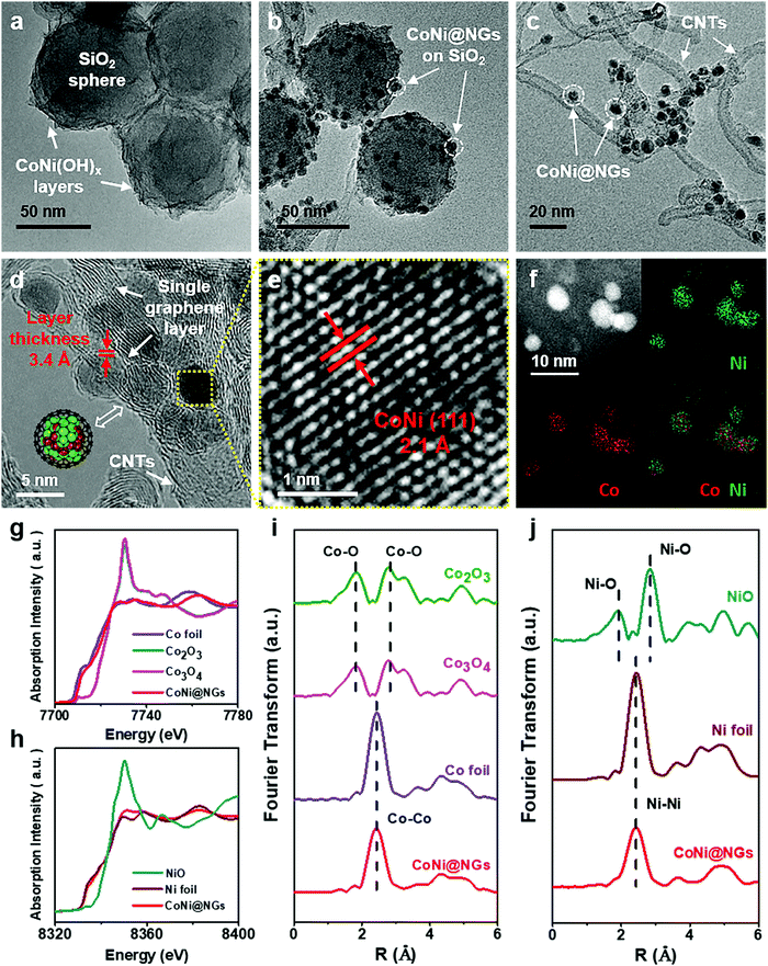
The chainmail catalyst was prepared through a template-assisted method, which is illustrated in Fig. S1, ESI.† First, CoNi hydroxide was precipitated on SiO2 templates to get the precursor CoNi(OH)x–SiO2. Then, the precursor was reduced to CoNi nanoparticles (NPs) under a reducing atmosphere, and CoNi NPs were encapsulated by graphene shells through a chemical vapor deposition (CVD) process at 600 °C. Finally, the chainmail catalyst named CoNi@NGs was obtained after etching the SiO2 templates. Besides, a series of control samples were synthesized, including reference chainmail catalysts with a single metal core of cobalt (Co@NGs) and nickel (Ni@NGs), cobalt and nickel oxide NPs loaded on carbon nanotubes (CNTs) named CoNiOx–CNTs, and a material obtained by removing the metal core of CoNi@NGs named N-Carbon.Transmission electron microscopy (TEM) and X-ray absorption fine structure (XAFS) analyses were employed to characterize the structural and electronic properties of the obtained CoNi@NGs. The TEM images in Fig. 1a–c clearly show the morphological changes in the process of the synthesis of CoNi@NGs. The precursor CoNi(OH)x layers are distributed homogeneously on the SiO2 templates (Fig. 1a and Fig. S2, ESI†). After CVD, numerous small NPs together with the formation of CNTs appear on the SiO2 templates (Fig. 1b and Fig. S3, ESI†). With the removal of the SiO2 templates, one can see metal NPs uniformly distributed on the interlaced CNTs (Fig. 1c). The high-resolution TEM (HRTEM) image (Fig. 1d) confirms that the metal NPs with an average diameter of 4–6 nm are completely encapsulated by a single layer graphene shell with a layer thickness of 3.4 Å. According to the statistical analysis of the HRTEM images, almost 96% of the graphene layers on CoNi NPs are a single layer (Fig. S4, ESI†). The elemental mapping images of metal NPs obtained by energy dispersive X-ray spectroscopy (EDX) indicate that the elemental distributions of Co and Ni encapsulated in the graphene shells are homogeneous (Fig. 1f). Inductively coupled plasma atomic emission spectroscopy (ICP-AES) shows that the mass contents of Co and Ni are 10.5% and 16.8%, respectively, in CoNi@NGs (Table S1, ESI†). The lattice fringes of the internal metal NPs display an interplanar spacing of 2.1 Å (Fig. 1e), which matches with the (111) plane of the CoNi alloy. Furthermore, XAFS, which is sensitive to the chemical states and coordination environments of atoms, indicates that the states of Co and Ni in CoNi@NGs are close to those of the corresponding metal foil references. This demonstrates that both Co and Ni are in the metallic state (Fig. 1g–j), which is also consistent with the X-ray diffraction (XRD) (Fig. S5, ESI†) and X-ray photoelectron spectroscopy (XPS) (Fig. S6, ESI†) results. These observations prove that the CoNi alloy NPs are completely encapsulated by the graphene shells, and NPs thus stay in the metallic state.
Electrocatalytic performance
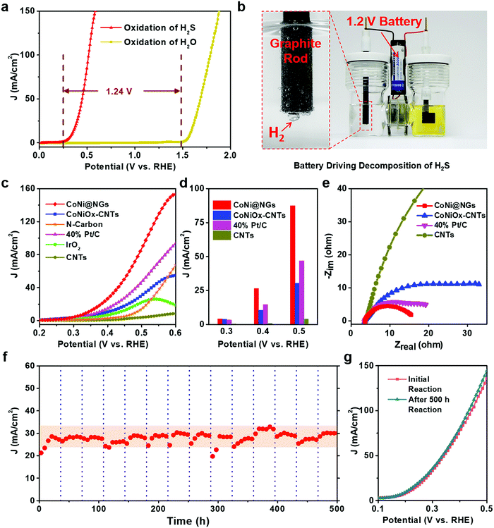
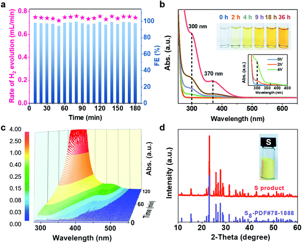
The electrocatalytic performance of CoNi@NGs for SOR was evaluated in Ar-saturated 1 M NaOH and 1 M Na2S solutions using a three-electrode system with Hg/HgO and a graphite rod as the reference electrode and counter electrode, respectively. Linear sweep voltammograms (LSVs) were recorded to evaluate the SOR performance of the catalysts. Compared with the onset potential for the anodic oxygen evolution reaction (OER) of electrocatalytic water splitting, the onset potential of optimal CoNi@NGs for SOR (Fig. S7, ESI†) was only 0.25 V (versus RHE) at 1 mA cm−2, which was 1.24 V lower than that of OER (Fig. 2a, Fig. S8 and Table S3, ESI†). Note that a 1.2 V commercial battery can easily drive the electrocatalytic decomposition of H2S, which produces abundant hydrogen bubbles on the graphite rod, as shown in Fig. 2b and in Video S1, ESI.† However, it is impossible to run the electrocatalytic splitting of H2O at such a low potential (Fig. S9 and Video S2, ESI†). This indicates that to produce the same amount of H2, the electrocatalytic decomposition of H2S consumes much less electrical energy, which clearly shows the advantage of low energy consumption for hydrogen production compared with electrocatalytic decomposition of H2O. In addition, CoNi@NGs show a better SOR performance than the reference CoNiOx–CNTs and N-carbon (Fig. 2c, d, Fig. S10–S12 and Table S4, ESI†), indicating that the graphene chainmail catalyst and the encapsulated CoNi cores play important roles in enhancing the SOR activity of CoNi@NGs. Moreover, compared with a series of materials mentioned in the previous works and some related potential catalysts, CoNi@NGs display superior activity than the control catalysts, including precious materials Pt/C and IrO2, metallic sulfides, metallic oxides, metal–organic compounds, and carbon catalysts (Fig. 2c, d and Table S5, ESI†). In particular, the current density of CoNi@NGs at 0.5 V was almost twice than that of commercial 40% Pt/C and much higher than that of the other catalysts. The electrochemical impedance spectra (EIS) of the materials (Fig. 2e, Fig. S13 and Table S6, ESI†) show that CoNi@NGs possess the lowest charge transfer resistance (Rct) value compared with other samples, further confirming the superior catalytic activity. Besides, in the 500 h durability measurements at 0.317 V (versus RHE), the current density of CoNi@NGs remained at around 30 mA cm−2 (Fig. 2f and Fig. S14, ESI†). The polarization curve after the 500 h durability test shows a high performance with almost no decay compared with the initial test (Fig. 2g), which indicates the excellent durability of CoNi@NGs. The HRTEM images of CoNi@NGs after the 500 h durability test are given in Fig. S15, ESI.† Note that the structures of CoNi NPs encapsulated in the graphene shells are well maintained, which further confirms the robustness of our chainmail catalysts in harsh environments. Overall, the high activity and remarkable durability of CoNi@NGs demonstrate their great potential for H2 production from the electrocatalytic decomposition of H2S.In order to clarify the actual yield and the reaction process of the electrocatalytic decomposition of H2S, the decomposition products and the electrolyte in the reaction were tested. In a galvanostatic test at 100 mA cm−2 current density, the amount of hydrogen production was maintained at around 0.74 mL min−1via real-time monitoring by gas chromatography, which extrapolated 98% faradaic efficiency of hydrogen production (Fig. 3a). As the reaction proceeded, the color of the electrolyte became yellow and gradually got deeper, as shown in the photo in Fig. 3b. In order to determine the mechanism of the anodic reaction, we designed an in situ electrochemical ultraviolet and visible (UV-Vis) spectrophotometry system to test the products in the electrolyte. The peaks shown at 300 nm, 370 nm and 420 nm correspond to the short-chain polysulfides (S22−–S42−) in the electrolyte (Fig. 3b, c and Fig. S16, ESI†).22–24 The signal strength of the polysulfides increased obviously as the reaction progressed, and the peak at 300 nm reached the limit of detection at the earliest and covered the peak at 370 nm in the in situ UV-Vis test results. Polysulfides were generated from the oxidation product sulfur further combining with the sulfides in the electrolyte.25 With the concentration of polysulfides increasing, the color of the electrolyte became darker. A yellow powder could be efficiently obtained through the acid treatment of the electrolyte,26,27 which corresponded to elemental sulfur, as confirmed by XRD analysis (Fig. 3d). Therefore, this demonstrates that CoNi@NGs accomplish the effective decomposition of H2S and simultaneously produce clean hydrogen and sulfur.
Mechanism investigation
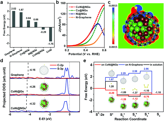
DFT calculations were performed to rationalize the superior activity of CoNi@NGs toward the electrocatalytic decomposition of H2S. The prevalent oxidation of S2− can occur in three different stages, i.e., an initial S2− state, an intermediate S* state, and S as the final product.28–30 Generally, the binding strength of the reaction intermediates to the electrode's surface can serve as a good measure of the electrocatalytic activity of a catalytic material.20,31,32 Therefore, a catalyst that gives a free energy of adsorbed S of approximately zero (ΔGS* ≈ 0) is considered a good candidate for SOR to compromise the reaction barriers of the adsorption and desorption steps. According to the computational results (Fig. 4a and Table S7, ESI†), pristine graphene, N-doped graphene shells and CoNi clusters have high |ΔGS*|, and too weak or too strong adsorption of sulfur hinders the high activity of materials. Interestingly, the catalytic activity of N-doped graphene is substantially improved when it encapsulates metal clusters, such as Co and Ni and their alloy. In particular, CoNi@NGs can exhibit a near thermo-neutral adsorption of sulfur with ΔGS* = −0.29 eV, which is much lower than that of N-doped graphene (1.87 eV). This confirms the better catalytic activity of CoNi@NGs, which agrees with the experimental results (Fig. 4b). In addition, the analysis of the computed SOR activity of CoNi@NGs consisting of two graphene layers showed that with the increase in the number of graphene layers, the promotion of sulfur absorption by the encapsulated CoNi clusters was substantially weakened. Nevertheless, the promotion is still prominent through two layers of graphene (Fig. S17, ESI†). The calculated projected density of states (DOS) in Fig. 4d shows a downshifted band center for the occupied state of the C–S bond (sum of C2p and S3p) on CoNi@NGs compared with that on CoNi@Gs and graphene. This means that the stronger S–C chemical bonding enhances the sulfur adsorption on graphene's surface and thereby enhances the SOR activity, which is consistent with the experimental results (Fig. S18, ESI†). Furthermore, the electronic state structure analysis in Fig. 4c reveals that the stabilization of the S* intermediate on CoNi@NGs may originate from the enriched charge density of the carbon atoms near the CoNi cluster and nitrogen dopants.Besides elemental sulfur, short-chain polysulfides including S2 to S4 are formed on the anode's surface under the operating conditions. We thus performed DFT calculations to elucidate the mechanisms responsible for polysulfide formation in the aqueous solution on N-graphene and CoNi@NGs.28–30 The schematic illustrations of the reaction paths are described in Fig. S19, ESI,† consisting of the different adsorbed S species from initial S* to S4*. The corresponding free energy profiles are given in Fig. 4e. It was shown that the formation energies of the Sx* intermediates of each reaction step for CoNi@NGs were obviously lower than those observed for the species formed in solution. Specifically, S2* on CoNi@NGs showed much better stability compared with the S3* and S4* species, suggesting that the short-chain S22− species may be the main product in the electrolyte, which was consistent with the experimental results.
Selective removal of H2S from industrial syngas to produce hydrogen by CoNi@NGs
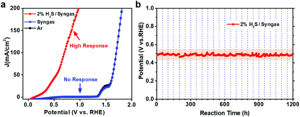
In order to determine the effectiveness of CoNi@NGs to utilize waste H2S for hydrogen production in a realistic system, we constructed a demo for the electrocatalytic selective removal of H2S from simulated industrial syngas (49% CO, 49% H2 and 2% H2S). The LSV test showed that CoNi@NGs had a high response current after introducing 2% H2S/syngas (Fig. 5a). In contrast, there was almost no response current for syngas without H2S at a wide potential, which was lower than the potential of oxygen evolution from water. This indicated that CoNi@NGs had high activity for the selective removal of H2S from syngas, while the main components CO and H2 in the syngas will not be consumed during the removal of the H2S impurities. Furthermore, the long-term galvanostatic test at 20 mA cm−2 current density showed that the potential of SOR could be well maintained at around 0.5 V (versus RHE) for over 1200 h (Fig. 5b, Fig. S20 and Table S8, ESI†), suggesting excellent stability in the selective removal of H2S from industrial syngas. These results demonstrate that the CoNi@NG electrocatalyst has high reliability to remove H2S impurities from industrial syngas for producing hydrogen.Conclusions
In summary, we developed a robust chainmail catalyst via a template-assisted strategy to achieve a CoNi nanoalloy encapsulated within an ultrathin N-doped graphene layer. This kind of chainmail catalyst had an ultralow onset potential of 0.25 V for anodic SOR, which was 1.24 V lower than that required for OER. It exhibited almost twice current density than the commercial precious metal Pt/C catalyst at 0.5 V potential. The optimized catalyst showed excellent durability without degradation even after 500 h and approximately 98% faradaic efficiency toward H2 production. The DFT calculations revealed that the high activity for SOR may originate from the modulation of the electronic structure of graphene's surface by encapsulating a metal alloy and doping with nitrogen, which facilitated the adsorption of S* and the formation of polysulfide intermediates on graphene's surface. Furthermore, we showed a demo for the direct utilization of the H2S impurities from industrial syngas to produce hydrogen employing the CoNi@NG catalyst, which showed high stability for more than 1200 h. This work demonstrated that the chainmail CoNi@NGs can be used as a low-cost, highly efficient and robust catalyst to achieve efficient conversion of the hazardous waste H2S gas into clean energy hydrogen and valuable chemical sulfur, which shows a promising potential for practical applications.Conflicts of interest
The authors declare no competing interests.Acknowledgements
We gratefully acknowledge the financial support from the Ministry of Science and Technology of China (No. 2016YFA0204100 and 2016YFA0200200), the National Natural Science Foundation of China (No. 21890753, 21573220 and 21988101), the Key Research Program of Frontier Sciences of the Chinese Academy of Sciences (No. QYZDB-SSW-JSC020), and the DNL Cooperation Fund, CAS (No. DNL180201). We thank the staff at the BL14W1 beamline of Shanghai Synchrotron Radiation Facilities (SSRF) for assistance with the XAFS measurements. We thank Dr Zhen Wang for the help in XPS tests. We thank Dr Mingrun Li and Dr Shuhong Zhang for the help in TEM tests.References
- W. Lubitz and W. Tumas, Chem. Rev., 2007, 107, 3900–3903 CrossRef CAS PubMed.
- M. Wang, L. Chen and L. Sun, Energy Environ. Sci., 2012, 5, 6763–6778 RSC.
- J. N. Tiwari, S. Sultan, C. W. Myung, T. Yoon, N. N. Li, M. Ha, A. M. Harzandi, H. J. Park, D. Y. Kim, S. S. Chandrasekaran, W. G. Lee, V. Vij, H. Kang, T. J. Shin, H. S. Shin, G. Lee, Z. Lee and K. S. Kim, Nat. Energy, 2018, 3, 773–782 CrossRef CAS.
- C. Hu, L. Zhang and J. Gong, Energy Environ. Sci., 2019, 12, 2620–2645 RSC.
- M. D. Lewan, Nature, 1998, 391, 164–166 CrossRef CAS.
- X. Zong, H. Chen, B. Seger, T. Pedersen, M. S. Dargusch, E. W. McFarland, C. Li and L. Wang, Energy Environ. Sci., 2014, 7, 3347–3351 RSC.
- G. J. Ma, H. J. Yan, J. Y. Shi, X. Zong, Z. B. Lei and C. Li, J. Catal., 2008, 260, 134–140 CrossRef CAS.
- A. PiÉPlu, O. Saur, J. C. Lavalley, O. Legendre and C. NÉDez, Catal. Rev., 1998, 40, 409–450 CrossRef.
- H. Y. Huang, Y. Yu and K. H. Chung, Energy Fuels, 2009, 23, 4420–4425 CrossRef CAS.
- K. Petrov and S. Srinivasan, Int. J. Hydrogen Energy, 1996, 21, 163–169 CrossRef CAS.
- A. A. Anani, Z. Mao, R. E. White, S. Srinivasan and A. J. Appleby, J. Electrochem. Soc., 1990, 137, 2703–2709 CrossRef CAS.
- P. M. Lessner, F. R. McLarnon, J. Winnick and E. J. Cairns, J. Appl. Electrochem., 1992, 22, 927–934 CrossRef CAS.
- I. Pikaar, R. A. Rozendal, Z. G. Yuan, J. Keller and K. Rabaey, Water Res., 2011, 45, 5381–5388 CrossRef CAS PubMed.
- E. Vaiopoulou, T. Provijn, A. Prevoteau, I. Pikaar and K. Rabaey, Water Res., 2016, 92, 38–43 CrossRef CAS PubMed.
- G. Hodes, J. Manassen and D. Cahen, J. Electrochem. Soc., 1980, 127, 544–549 CrossRef CAS.
- L. Su, A. F. Badel, C. Cao, J. J. Hinricher and F. R. Brushett, Ind. Eng. Chem. Res., 2017, 56, 9783–9792 CrossRef CAS.
- D. H. Deng, L. Yu, X. Q. Chen, G. X. Wang, L. Jin, X. L. Pan, J. Deng, G. Q. Sun and X. H. Bao, Angew. Chem., Int. Ed., 2013, 52, 371–375 CrossRef CAS PubMed.
- J. Deng, P. J. Ren, D. H. Deng, L. Yu, F. Yang and X. H. Bao, Energy Environ. Sci., 2014, 7, 1919–1923 RSC.
- J. Deng, P. J. Ren, D. H. Deng and X. H. Bao, Angew. Chem., Int. Ed., 2015, 54, 2100–2104 CrossRef CAS PubMed.
- X. J. Cui, P. J. Ren, D. H. Deng, J. Deng and X. H. Bao, Energy Environ. Sci., 2016, 9, 123–129 RSC.
- Y. C. Tu, P. J. Ren, D. H. Deng and X. H. Bao, Nano Energy, 2018, 52, 494–500 CrossRef CAS.
- C. A. Linkous, C. P. Huang and J. R. Fowler, J. Photochem. Photobiol., A, 2004, 168, 153–160 CrossRef CAS.
- B. R. S. Lemos, I. F. Teixeira, J. P. de Mesquita, R. R. Ribeiro, C. L. Donnici and R. M. Lago, Carbon, 2012, 50, 1386–1393 CrossRef CAS.
- C. Barchasz, F. Molton, C. Duboc, J. C. Lepretre, S. Patoux and F. Alloin, Anal. Chem., 2012, 84, 3973–3980 CrossRef CAS PubMed.
- Y. T. Wu and N. Liu, Chem, 2018, 4, 438–465 CAS.
- Q. L. Zhang, I. G. Dalla Lana, K. T. Chuang and H. Wang, Ind. Eng. Chem. Res., 2000, 39, 2505–2509 CrossRef CAS.
- J. P. Fornés and J. M. Bisang, Electrochim. Acta, 2017, 243, 90–97 CrossRef.
- I. C. Hamilton and R. Woods, J. Appl. Electrochem., 1983, 13, 783–794 CrossRef CAS.
- P. L. Allen and A. Hickling, Trans. Faraday Soc., 1957, 53, 1626–1635 RSC.
- P. K. Dutta, K. Rabaey, Z. G. Yuan and J. Keller, Water Res., 2008, 42, 4965–4975 CrossRef CAS PubMed.
- J. K. Nørskov, T. Bligaard, A. Logadottir, J. R. Kitchin, J. G. Chen, S. Pandelov and U. Stimming, J. Electrochem. Soc., 2005, 152, J23–J26 CrossRef.
- B. Hinnemann, P. G. Moses, J. Bonde, K. P. Jorgensen, J. H. Nielsen, S. Horch, I. Chorkendorff and J. K. Norskov, J. Am. Chem. Soc., 2005, 127, 5308–5309 CrossRef CAS PubMed.
Footnotes |
| † Electronic supplementary information (ESI) available. See DOI: 10.1039/c9ee03231b |
| ‡ These authors have contributed equally. |
| This journal is © The Royal Society of Chemistry 2020 |

