 Open Access Article
High-performance solid-state Zn batteries based on a free-standing organic cathode and metal Zn anode with an ordered nano-architecture†
Xingchi
Xiao‡
ab,
Wenjie
Liu‡
ab,
Kai
Wang
 *ab,
Chen
Li
 ab,
Xianzhong
Sun
ab,
Xiong
Zhang
ab,
Wenhao
Liu
ab and
Yanwei
Ma
ab,
Xianzhong
Sun
ab,
Xiong
Zhang
ab,
Wenhao
Liu
ab and
Yanwei
Ma
 *ab
*ab
aInstitute of Electrical Engineering, Chinese Academy of Sciences, Beijing 100190, P. R. China. E-mail: wangkai@mail.iee.ac.cn; ywma@mail.iee.ac.cn
bUniversity of Chinese Academy of Sciences, Beijing 100049, PR China
First published on 10th November 2019
Abstract
The increasing demand for large-scale manufacture of wearable electronics requires applicable energy storage devices with high-performance and safety. In this paper, we reported a solid-state Zn battery based on a free-standing organic cathode and metal Zn anode with an orderly aligned nano-architecture. The cathode is fabricated by depositing organic nanowire arrays on a carbon nanotube film via an in situ polymerization process, and the anode was prepared by electrodepositing Zn nanosheet arrays on carbon cloth. To avoid electrolyte leakage risks, a pseudo-solid-state PAAM-ZnSO4 gel electrolyte is employed, which is synthesized via a chemical cross-linking and film casting approach. The orderly aligned nanostructure of PANI nanowire arrays and zinc nanosheet arrays exhibits superior electrochemical performance, while the free-standing electrode configuration simplifies the battery fabrication process and offers excellent flexibility. The resulting solid-state Zn battery delivered a high capacity of 144 mA h g−1 at a current density of 0.2 A g−1, a 91.1% capacity retention after 150 cycles at a current density of 0.5 A g−1, and excellent flexibility under different bending states. This high-performance solid-state Zn battery provides a promising alternative energy storage device for next generation wearable electronics.
Introduction
Wearable electronics, such as healthcare biosensors, smart phones, and activity trackers, have attracted considerable attention from both the academic and industrial communities in the past few decades due to their advantage over traditional rigid and bulky electronics, including ultra-flexibility, light weight, conformability and high integration with the human body.1,2 As a significant component of electronic devices, conventional electrochemical energy storage devices (e.g. supercapacitors and batteries) severely restrict the large-scale commercialization of these flexible wearable electronics.3–5 New materials and nanostructure for flexible energy storage devices with improved performance and high safety have been proposed and extensively studied to satisfy the requirements of wearable electronics.4,6Compared with prevalent lithium-ion batteries based on flammable organic electrolytes, aqueous batteries are more suitable candidates for flexible electronics due to their low-cost, good safety, environment friendliness, and simple fabrication process without needing a glovebox.7–10 Among various aqueous batteries, zinc-ion batteries are more attractive than alkaline-ion batteries (Li+, Na+, K+ and Mg2+) owing to the excellent properties of zinc metals, which include a relatively low redox potential versus the standard hydrogen electrode (−0.76 V), high theoretical capacity (819 mA h g−1), good electrochemical stability against water and oxygen which provides a high operating voltage window (∼2 V) and large abundance in the earth's crust.11–13 However, bulk zinc foils are not ideal electrodes for flexible electronics because of their rigid characteristics and high density. Combining metals with flexible substrates, carbon-based materials with good electrical conductivity and high mechanical stability, can be an efficient solution for the preparation of highly flexible and stretchable metal electrodes.14
The cathode materials for aqueous Zn batteries are mainly some metal oxides, such as manganese oxide and vanadium oxide, which hinder the development of Zn-ion batteries due to their poor cyclability and sluggish kinetics.11,15 Organic cathode materials have attracted growing interest over inorganic materials since they possess good mechanical strength, flexibility, and better biocompatibility.16–18 As a typical conducting polymer, polyaniline (PANI) shows high conductivity, multiple reversible redox/doping states, and good stability in water and air.19,20 Besides, PANI is a good candidate to construct flexible electrodes for Zn-ion batteries considering the inherent flexibility of polymer materials.21,22 However, the application of PANI nanowire array flexible cathodes for Zn-ion batteries has not been reported so far.
Gel polymer electrolytes are normally employed by incorporating a liquid electrolyte into the host polymer, in order to avoid the electrolyte leakage during bending cycles for the practical application of flexible aqueous batteries. Poly(vinyl alcohol) is a widely used polymer host for gel electrolytes; however, it suffers from rapid self-discharge and poor compressibility and stretchability.23 Polyacrylamide (PAAM), a kind of polymer host material, shows better mechanical strength and higher ionic conductivity by dissolving large amounts of aqueous electrolyte.14,24–26
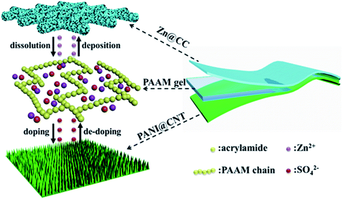
Herein, we developed a solid-state Zn battery with a sandwich-like structure consisting of two flexible free-standing electrodes and a PAAM-ZnSO4 gel electrolyte film, as shown in Scheme 1. Polyaniline nanowire arrays are in situ polymerized on a carbon nanotube (CNT) film as a flexible cathode (PANI@CNT), and zinc nanosheet arrays are electrodeposited on carbon cloth (CC) as a flexible anode (Zn@CC). The fabricated solid-state Zn battery exhibited a high specific capacity of 144 mA h g−1 and good cycling stability (91.1% capacity retention after 150 cycles at a current density of 0.5 A g−1). In addition, the as-prepared Zn battery demonstrated excellent flexibility under different bending states.
Experimental section
Materials
Aniline, ammonium persulfate (APS), a metal zinc plate, acrylamide (AAM), N,N′-methylenebisacrylamide (BIS), and potassium persulfate (KPS) were purchased from Alfa-Aesar, which were used directly without further purification. Carbon nanotubes (CNTs) were obtained from Chengdu Organic Chemical Co. Ltd., Chinese Academy of Sciences. Zinc sulfate (ZnSO4), a cellulose separator, and perchloric acid (HClO4) were purchased from Sinopharm Chemical Reagent Co. Ltd.Preparation of the PANI@CNT flexible cathode
The free-standing CNT film was prepared by the vacuum filtration of dispersed CNT solution. The PANI@CNT flexible cathode was then obtained by an in situ polymerization process. Typically, the aniline monomer (36.5 μL, 0.04 mmol) was added into 30 mL HClO4 aqueous solution (1 mol L−1), which was denoted as solution A. The CNT film (4 cm × 2 cm) was placed into solution A after UV-Ozone treatment. Ammonium persulfate (0.27 mmol) was dissolved in 10 mL HClO4 aqueous solution (1 mol L−1), which was called solution B. Both solutions were cooled in an ice bath (0 °C) with magnetic stirring and maintained for 30 minutes, and then solution B was added to solution A dropwise; in this case the concentration of aniline was 0.01 mol L−1. After reaction for 24 h, the film was removed and washed three times with deionized water to remove oligomers and other residuals, and then dried overnight with the lyophilisation process. Control experiments with various concentrations of aniline (0.05 and 0.1 mol L−1, respectively) were conducted with a similar process. The weight of PANI deposited on the CNT film was calculated from the weight difference before and after the polymerization process.Preparation of the Zn@carbon cloth anode
The Zn@carbon cloth (CC) flexible anode was prepared via an electrochemical deposition method with a two-electrode system, where carbon cloth (4 cm × 2 cm) was used as the working electrode and a zinc plate (4 cm × 2 cm) was used as both reference and counter electrodes. ZnSO4 aqueous solution (0.5 mol L−1) was used as the electrolyte. After electrodeposition at a constant voltage (−0.8 V vs. zinc plate) for 30 minutes, the Zn@CC electrode was washed with deionized water three times and dried at room temperature in a vacuum. The mass loading of zinc on the CC was calculated from the weight difference before and after electrodeposition.Preparation of the polymer electrolyte gel film
A certain amount of acrylamide (AAM) monomer (30 wt% relative to deionized water) and cross linker N,N′-methylenebisacrylamide (BIS, 0.05 wt% related to monomer) was added to 30 mL ZnSO4 aqueous solution (1 mol L−1) with magnetic stirring at room temperature for 30 minutes. Then, the initiator potassium persulfate (KPS, 1.5 wt% relative to the monomer) was added to the above solution with magnetic stirring for 5 minutes. The above solution was poured into a plastic Petri dish before gelation to form a gel film. The as-prepared gel film was cut into a circular form with a diameter of 1 cm and placed between two metal plates in a Swagelok™ cell to measure the ionic conductivity through electrochemical impedance spectroscopy (EIS) in the frequency range of 0.1–106 Hz on an Electrochemical-Lab workstation. The ionic conductivity (σ) can be obtained according to the equation σ = L/(R × S), where L, R, are S are the thickness, resistance and area of the gel film, respectively.Materials characterization
The surface morphology of the CNT film, carbon cloth and flexible electrodes was determined by using a scanning electron microscope (SEM). The structure and composition of the as-prepared samples were determined by using an X-ray diffraction (XRD) spectroscope with the scan range of 5–80° by using a Cu-Kα radiation source, and a Raman spectroscope with the wavelength range of 400–4000 cm−1.Assembly and electrochemical measurement of the flexible solid-state Zn battery
The flexible solid-state zinc battery was assembled with a sandwich-like structure, in which the flexible cathode and anode were separated by a slightly larger gel electrolyte film, and then were encapsulated by a flexible polyethylene terephthalate (PET) film. Two pieces of thin carbon cloth were connected to the edge of the flexible electrodes to ensure a good electrical contact during electrochemical measurements. Cyclic voltammetry (CV) and galvanostatic charge–discharge (GCD) measurements in the potential range of 0.3–1.6 V were conducted on an Electrochemical-Lab workstation. For Zn batteries, the gravimetric specific capacity Q = JΔt, where J is the current density and Δt is the discharge time per cycle. The energy density , and the power density P = E/Δt, where V is the discharge voltage.
Results and discussion
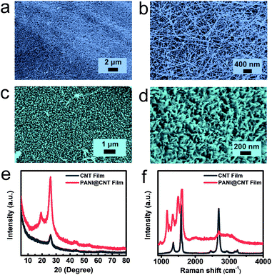
An ordered nanostructure possesses an optimized charge transport path and sufficient ion accessibility, leading to a fast and high efficiency electrochemical process, and is hence considered as an ideal electrode structure for electrochemical energy storage. In this work, ordered PANI nanowire arrays are used as an active material to construct the flexible cathode. The CNT film was chosen as the substrate for the flexible cathode in our experiment due to its unique properties including high electrical conductivity and substantial mechanical strength. Vertically conducting PANI nanowires were directly deposited on the CNT film via a facile chemical in situ polymerization process by using aniline as the monomer and ammonium persulfate as the initiator under ice-bath conditions. The PANI@CNT film appears to have a cyan colour with high bendability, as shown in Fig. S1.†Fig. 1a and b present the morphologies of the UV-Ozone treated CNT film in low- and high-magnification SEM images, respectively. It is clear that the film is woven from CNT bundles with a diameter of around 10 nanometers; the tight connection of these bundles promises the high conductivity and mechanical strength of the CNT film. After chemical in situ polymerization, PANI nanowires are uniformly deposited on the surface of the CNT film, which look as green dots from the top view, as illustrated in Fig. 1c. But separately aligned PANI nanowires with a diameter of around 20 nm, which are perpendicular to the substrate, can be clearly demonstrated when we tilted the sample by 30° during SEM tests (Fig. 1d). The formation of vertical PANI nanowires by using a dilute aniline solution can be explained by a seedling growth mechanism.27,28 When the concentration of the monomer is low, most active nucleation centers are formed first on the solid substrate to minimize the interfacial energy for the subsequent polymerization process. The nucleation process further decreases the concentration of aniline and thus inhibits the emergence of new active nucleation on the substrate. So the PANI nanowires only grow along the existing active nucleus to form vertical PANI nanowire arrays. On the other hand, the polymerization process can also occur in the bulk solution if the concentration of the monomer is high, which results in the appearance of disordered PANI fibers with large diameters of around several hundred nanometers.The chemical structures and composition of the pure CNT film and PANI@CNT film were further demonstrated by XRD and Raman spectroscopy. According to Fig. 1e, the diffraction peak of CNTs at around 26° corresponds to the reflection peak of (002) graphitic crystal planes, and the diffraction peaks at 19.2° and 26° in the PANI@CNT film can be attributed to the (020) and (200) crystal planes of PANI nanowires in the emeraldine salt form.20,29 The sharp patterns of PANI diffraction peaks indicate the high crystallinity degree and uniform orientation of the deposited PANI nanowires on the CNT film. The Raman spectra in Fig. 1f show the D-band, G-band and 2D-band peaks at 1350, 1580 and 2691 cm−1 of the CNT film, representing the disordered features of sp2 domains, the first-order scattering of the E2g mode, and the resonance of two phonons, respectively.30,31 After deposition of PANI nanowires on the CNT film, a series of characteristic peaks of PANI appeared overlapping with the D and G-band peaks of the CNT film at 1169, 1222, 1343, 1496, 1588 and 1620 cm−1, which are assigned to the C–H in-plane bending of the quinoid ring, C–C ring deformation of the quinoid ring, C![[double bond, length as m-dash]](https://www.rsc.org/images/entities/char_e001.gif) N stretching of the quinoid ring, C
N stretching of the quinoid ring, C![[double bond, length as m-dash]](https://www.rsc.org/images/entities/char_e001.gif) C stretching vibration of the quinoid ring, C–H bending of the benzenoid ring, and C–C stretching of the benzenoid ring, representing the deposition of PANI nanowires.32,33
C stretching vibration of the quinoid ring, C–H bending of the benzenoid ring, and C–C stretching of the benzenoid ring, representing the deposition of PANI nanowires.32,33
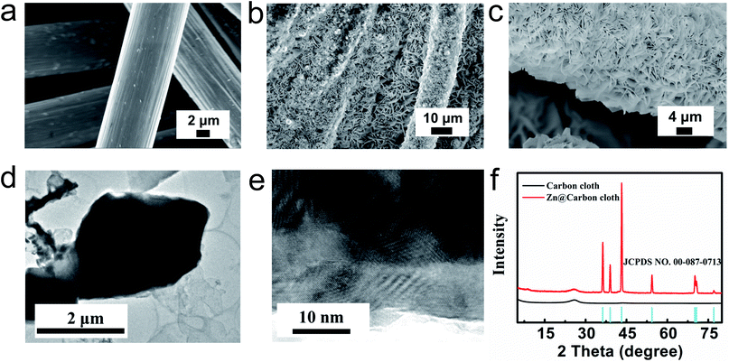
The flexible Zn@CC anode was fabricated by a facile electrodeposition method. The carbon cloth (CC) is woven from smooth carbon fibers with a diameter of about 10 μm, as shown in Fig. 2a. After the electroplating process of zinc, the surface of carbon nanofibers was covered by uniform zinc nanosheet arrays (Fig. 2b and c). From cross-sectional images of the Zn@CC anode (Fig. S2†), the thickness of the as-deposited Zn nanosheet is 2–4 μm. The spaces between zinc nanosheet arrays can increase the surface area of the electrode, and improve the penetration of electrolyte solution. The ordered array nanostructure can also tolerate the volume change during the charge–discharge process. Fig. 2d shows the transmission electron microscopy (TEM) image of the zinc nanosheet. From high-resolution TEM in Fig. 2e, the interlayer distance is around 0.25 nm which is in accordance with the (002) plane of Zn, and this result is also consistent with the XRD pattern (Fig. 2f).The chemical composition and crystalline structure of electrodeposited zinc nanosheet arrays on carbon cloth were characterized by using the XRD pattern in Fig. 2f. The diffraction peaks located at 36.3°, 39°, 43.2°, 54.3°, 70.1°, 70.6° and 77° can be assigned to the reflection peaks of (002), (100), (101), (102), (103), (110) and (004) crystal planes, respectively, which are well indexed to the standard zinc XRD pattern (JCPDS: NO. 00-087-0713).
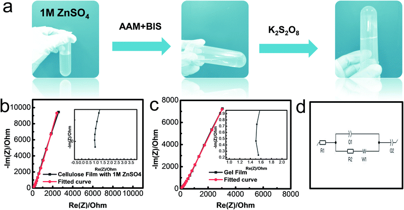
The conductive polyacrylamide (PAAM)-ZnSO4 hydrogels were synthesized via a simple cross-linking process, as shown in Fig. 3a. The electrolyte solution ZnSO4 (1 mol L−1) maintained the flowing state after adding the monomer AAM and cross-linker BIS. The solution transformed into the hydrogel state with the loss of fluidity when the initiator KPS was added. The ionic conductivity of the gel film was measured by using an electrochemical impedance spectroscope (EIS) from 100 mHz to 1 MHz. The Nyquist plots of two different samples, namely a common cellulous film with an electrolyte and PAAM-ZnSO4 gel film, are shown in Fig. 3b and c, respectively. The equivalent circuit (Fig. 3d) consists of two capacitances (C1 and C2), inductance (W1), series resistance (R1) and charge-transfer resistance (R2).34 According to the high-frequency region in the inset figures, the series resistances can be obtained from the interception of Nyquist plots with the real axis; and the charge-transfer resistances can be extrapolated from the diameter of semicircles from high-frequency to medium-frequency.35 Therefore, the equivalent resistances Req of the cellulous film-1 M ZnSO4 and PAAM-ZnSO4 gel film can be obtained through the EIS curve, and the ionic conductivity is calculated via the equation σ = L/(Req × S), and the results are summarized in Table S1.† According to our experiment, the ionic conductivity of the PAAM-ZnSO4 gel film is 5.56 mS cm−1, which is comparable to that of the ZnSO4 aqueous electrolyte.
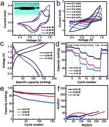
The flexible solid-state zinc battery was assembled in an atmospheric environment with a sandwich structure by using the PANI@CNT film as the cathode, Zn@CC as the anode and the PAAM-ZnSO4 gel film as the separator, as illustrated in the inset image of Fig. 4a. The electrochemical properties of flexible batteries with various monomer aniline concentrations of 0.01 M, 0.05 M, and 0.1 M were measured in this work. The batteries based on different PANI@CNT electrodes prepared with various aniline concentrations of 0.01 M, 0.05 M and 0.1 M are denoted as 0.01 M-battery, 0.05 M-battery and 0.1 M-battery, respectively. The cyclic voltammetry curves are shown in Fig. 4a in a potential window of 0.3–1.6 V at a scan rate of 0.2 mV s−1, exhibiting two pairs of distinct redox peaks of PANI, which are ascribed to the conversion of the leucoemeraldine (LE)/emeraldine salt (ES) and ES/pernigraniline (PN) states of PANI.19,27,36,37 When the concentration of aniline increases to 0.05 M and 0.1 M, the redox peaks shift right and the CV curves become steeper at 1.6 V, indicating that a thick PANI layer needs a higher overpotential. Fig. 4b shows the CV curves at various scan rates of the 0.01 M-battery. The starting several charge–discharge cycle profiles of the batteries are presented in Fig. 4c and S3† at a current density of 0.2 A g−1. Two voltage plateaus appearing at 1.1 V during the discharge process and 1.2 V during the charge process are observed on the charge–discharge curve of the 0.01 M-battery, which is in accordance with the results of the CV test. During the discharge process, Zn@CC is oxidized and PANI is reduced with the de-doping of SO42−, while during the charge process, Zn2+ deposits on the anode and PANI is oxidized with the doping of SO42−. Hence, the overall reaction can be described as:38
| nZn + PANI (ES) (SO42−)n ↔ nZn2+ + PANI (LE) + nSO42−. |
For comparison, the voltage platforms during the charge–discharge process are not obvious for the 0.05 M- and 0.1 M-battery, which is ascribed to the sluggish kinetics of the thick PANI layer.
The rate performance was measured by galvanostatic charge–discharge (GCD) measurements at current density from 0.2 A g−1 to 1 A g−1 with 5 consecutive test cycles. From Fig. 4d, the specific capacity of the 0.01 M-battery is 144 mA h g−1 at a current density of 0.2 A g−1, decreases slightly with the increase of current density, and can recover to the original value when the current density is back to 0.2 A g−1. The relative galvanostatic charge–discharge profiles are shown in Fig. S4.† The capacity is close to half of the theoretical value, since the complete oxidation states from LE to ES to PN cannot be fully realized in the electrolyte.33 However, the specific capacities of the 0.05 M- and 0.1 M-battery are much lower than the value of the 0.01 M-battery at high current density. The capacity of the 0.01 M-battery, 0.05 M-battery and 0.1 M-battery is 90 mA h g−1, 47 mA h g−1 and 30 mA h g−1 at a current density of 1 A g−1, respectively. The EIS plots and rate performance of the Zn ion batteries based on the Zn@CC anode are similar to those of the metal Zn foil anode according to our experiments, demonstrating that the as-prepared Zn@CC has similar fast transport properties to the metal Zn foil (Fig. S5†). The specific capacity of the 0.01 M-battery is comparable to and even better than that of most organic cathode based Zn ion batteries, which is summarized in Table S2.† The cycling stability was measured by GCD at a current density of 0.5 A g−1 (Fig. 4e). After 150 charge–discharge cycles, the capacity of the 0.01 M-battery remains at 98 mA h g−1 which is 91.1% of the initial capacity, indicating its excellent long-term stability. As for the 0.05 M- and 0.1 M-battery, the capacities just retain 75% and 64% of the initial values, respectively, after long-term cycling measurements. The galvanostatic charge–discharge curves before and after cycling at 0.5 A g−1 of the 0.01 M-battery, 0.05 M-battery and 0.1 M-battery are shown in Fig. S6.† In addition, the energy density E of the 0.01 M-battery is 135.45 W h kg−1 at a power density P of 187.30 W kg−1. For the 0.05 M-battery and 0.1 M-battery, the energy density is 113.56 W h kg−1 and 109.65 W h kg−1, respectively.
The superior capacity, rate performance and cycling stability of the 0.01 M-battery over the 0.05 M- and 0.1 M-battery can be explained by the different material structure of PANI deposited on the CNT film with various monomer concentrations. When the concentration of aniline increased to 0.05 and 0.1 mol L−1, the nanowire array structure of PANI disappeared, leaving a dense and thick aggregation of PANI coarse fibers (Fig. S7†). The drawbacks of PANI coarse fibers are that only the outer layers contribute to the capacity, leading to a low capacity. In addition, the thick polymer layer easily detaches from the electrode during the charge–discharge process, resulting in a poor stability and short lifetime.39,40 On the other hand, the vertically aligned structure shows several advantages over disordered nanofibers: (1) the small diameter of nanowires leads to a larger active surface area, which can contribute to larger capacity; (2) the charge transport is more efficient with a shorter diffusion length because of the ordered one-dimensional pathway, which promises a high rate performance, which is confirmed by the EIS tests (Fig. 4f); (3) the nanowire array structure provides sufficient space to accommodate the large volume changes during the charge–discharge process, leading to an improved stability and lifetime.
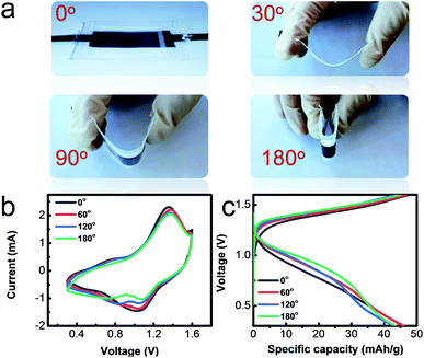
The excellent flexibility of the as-prepared solid-state 0.1 M-battery was demonstrated by bending the battery at different angels of 0°, 30°, 90° and 180°, as shown in Fig. 5a. The CV curves (Fig. 5b) at a scan rate of 0.2 mV s−1 with the operating potential range from 0.3 to 1.6 V and charge–discharge profiles (Fig. 5c) at a current density of 0.5 A g−1 of the solid-state battery exhibit no obvious change under different bending states and consecutive bending cycles (Fig. S8†), indicating its good bendability.
Conclusions
In summary, a high-performance solid-state zinc battery is developed based on a free-standing organic PANI nanowire array cathode and Zn nanosheet array anode in this work. The PANI nanowire array based free-standing electrode is fabricated by CNT vacuum assembly and an in situ aniline chemical polymerization process. The Zn@CC free-standing anode is prepared by electrodeposition of nanosheet arrays on carbon cloth. The electrolyte is a PAAM-ZnSO4 gel polymer electrolyte film synthesized via a cross-linking approach. The orderly aligned nanostructure of PANI nanowires and zinc nanosheets exhibits a large electrochemically active surface area and optimized electron and ion transport path, which endow the as-prepared battery with superior electrochemical performance. The solid-state zinc battery shows a high specific capacity of 144 mA h g−1, and excellent cycling stability with a capacitance retention of 91.1% after 150 cycles. In addition, the as-prepared Zn battery also showed an outstanding flexibility under different bending states with no noticeable change in its electrochemical performance. Based on our results, this flexible solid-state Zn battery is a novel next generation energy storage device for wearable electronics.Conflicts of interest
There are no conflicts to declare.Acknowledgements
We acknowledge the financial support of the National Natural Science Foundation of China (Grant 51822706, 51777200 and 51472238), Youth Innovation Promotion Association of CAS (No. 2017177), Innovative-Talent Program (Institute of Electrical Engineering, Chinese Academy of Sciences), and Beijing Municipal Science and Technology Commission (Grant No. Z171100000917007).Notes and references
- W. Weng, P. N. Chen, S. S. He, X. M. Sun and H. S. Peng, Angew. Chem., Int. Ed., 2016, 55, 6140–6169 CrossRef CAS.
- A. G. Avila and J. P. Hinestroza, Nat. Nanotechnol., 2008, 3, 458–459 CrossRef CAS.
- A. M. Zamarayeva, A. E. Ostfeld, M. Wang, J. K. Duey, I. Deckman, B. P. Lechene, G. Davies, D. A. Steingart and A. C. Arias, Sci. Adv., 2017, 3, e1602051 CrossRef.
- Z. P. Wu, Y. L. Wang, X. B. Liu, C. Lv, Y. S. Li, D. Wei and Z. F. Liu, Adv. Mater., 2019, 31, 1800716 CrossRef PubMed.
- Y. Q. Liu, K. He, G. Chen, W. R. Leow and X. D. Chen, Chem. Rev., 2017, 117, 12893–12941 CrossRef CAS PubMed.
- A. M. Gaikwad, H. N. Chu, R. Qeraj, A. M. Zamarayeva and D. A. Steingart, Energy Technol., 2013, 1, 177–185 CrossRef CAS.
- H. Kim, J. Hong, K. Y. Park, S. W. Kim and K. Kang, Chem. Rev., 2014, 114, 11788–11827 CrossRef CAS.
- W. H. Ren, X. J. Chen and C. Zhao, Adv. Energy Mater., 2018, 8, 1801413 CrossRef.
- W. H. Ren, M. S. Qin, Z. X. Zhu, M. Y. Yan, Q. Li, L. Zhang, D. N. Liu and L. Q. Mai, Nano Lett., 2017, 17, 4713–4718 CrossRef CAS PubMed.
- M. Qin, W. Ren, J. Meng, X. Wang, X. Yao, Y. Ke, Q. Li and L. Mai, ACS Sustainable Chem. Eng., 2019, 7, 11564–11570 CrossRef CAS.
- L. N. Chen, M. Y. Yan, Z. W. Mei and L. Q. Mai, J. Inorg. Mater., 2017, 32, 225–234 CrossRef.
- D. C. R. Espinosa, A. M. Bernardes and J. A. S. Tenorio, J. Power Sources, 2004, 135, 311–319 CrossRef CAS.
- D. Kundu, B. D. Adams, V. D. Ort, S. H. Vajargah and L. F. Nazar, Nat. Energy, 2016, 1, 16119 CrossRef CAS.
- H. F. Li, Z. X. Liu, G. J. Liang, Y. Huang, Y. Huan, M. S. Zhu, Z. X. Pei, Q. Xue, Z. J. Tang, Y. K. Wang, B. H. Li and C. Y. Zhi, ACS Nano, 2018, 12, 3140–3148 CrossRef CAS PubMed.
- M. Song, H. Tan, D. L. Chao and H. J. Fan, Adv. Funct. Mater., 2018, 28, 1802564 CrossRef.
- A. L. Xia, X. M. Pu, Y. Y. Tao, H. M. Liu and Y. G. Wang, Appl. Surf. Sci., 2019, 481, 852–859 CrossRef CAS.
- J. H. Huang, Z. W. Guo, Y. Y. Ma, D. Bin, Y. G. Wang and Y. Y. Xia, Small Methods, 2019, 3, 1800272 CrossRef.
- Z. W. Guo, Y. Y. Ma, X. L. Dong, J. H. Huang, Y. G. Wang and Y. Y. Xia, Angew. Chem., Int. Ed., 2018, 57, 11737–11741 CrossRef CAS.
- J. H. Huang, Z. Wang, M. Y. Hou, X. L. Dong, Y. Liu, Y. G. Wang and Y. Y. Xia, Nat. Commun., 2018, 9, 2906 CrossRef PubMed.
- K. Wang, X. Zhang, C. Li, X. Z. Sun, Q. H. Meng, Y. W. Ma and Z. X. Wei, Adv. Mater., 2015, 27, 7451–7457 CrossRef CAS PubMed.
- H. F. Li, C. P. Han, Y. Huang, M. S. Zhu, Z. X. Pei, Q. Xue, Z. F. Wang, Z. X. Liu, Z. J. Tang, Y. K. Wang, F. Y. Kang, B. H. Li and C. Y. Zhi, Energy Environ. Sci., 2018, 11, 941–951 RSC.
- Z. Q. Wang, N. Bramnik, S. Roy, G. Di Benedetto, J. L. Zunino and S. Mitra, J. Power Sources, 2013, 237, 210–214 CrossRef CAS.
- H. L. Li, T. Lv, H. H. Sun, G. J. Qian, N. Li, Y. Yao and T. Chen, Nat. Commun., 2019, 10, 536 CrossRef PubMed.
- Z. F. Wang, H. F. Li, Z. J. Tang, Z. X. Liu, Z. H. Ruan, L. T. Ma, Q. Yang, D. H. Wang and C. Y. Zhi, Adv. Funct. Mater., 2018, 28, 1804560 CrossRef.
- F. N. Mo, G. J. Liang, Q. Q. Meng, Z. X. Liu, H. F. Li, J. Fan and C. Y. Zhi, Energy Environ. Sci., 2019, 12, 706–715 RSC.
- L. O. O. Ma, Y. W. Zhao, X. X. Ji, J. Zeng, Q. Yang, Y. Guo, Z. D. Huang, X. L. Li, J. Yu and C. Y. Zhi, Adv. Energy Mater., 2019, 9, 1900509 CrossRef.
- J. J. Xu, K. Wang, S. Z. Zu, B. H. Han and Z. X. Wei, ACS Nano, 2010, 4, 5019–5026 CrossRef CAS PubMed.
- N. R. Chiou, C. M. Lui, J. J. Guan, L. J. Lee and A. J. Epstein, Nat. Nanotechnol., 2007, 2, 354–357 CrossRef CAS PubMed.
- J. Yan, T. Wei, Z. J. Fan, W. Z. Qian, M. L. Zhang, X. D. Shen and F. Wei, J. Power Sources, 2010, 195, 3041–3045 CrossRef CAS.
- J. G. Kim, H. Kang, Y. Lee, J. Park, J. Kim, T. K. Truong, E. S. Kim, D. H. Yoon, Y. H. Lee and D. Suh, Adv. Funct. Mater., 2017, 27, 1701108 CrossRef.
- P. H. Tan, S. L. Zhang, K. T. Yue, F. M. Huang, Z. J. Shi, X. H. Zhou and Z. N. Gu, J. Raman Spectrosc., 1997, 28, 369–372 CrossRef CAS.
- I. Sedenkova, M. Trchova and J. Stejskal, Polym. Degrad. Stab., 2008, 93, 2147–2157 CrossRef CAS.
- J. E. P. da Silva, D. L. A. de Faria, S. I. C. de Torresi and M. L. A. Temperini, Macromolecules, 2000, 33, 3077–3083 CrossRef.
- P. L. Taberna, P. Simon and J. F. Fauvarque, J. Electrochem. Soc., 2003, 150, A292–A300 CrossRef CAS.
- S. S. Zhang, K. Xu and T. R. Jow, Electrochim. Acta, 2004, 49, 1057–1061 CrossRef CAS.
- H. D. Tran, D. Li and R. B. Kaner, Adv. Mater., 2009, 21, 1487–1499 CrossRef CAS.
- Y. L. Yin, C. H. Liu and S. S. Fan, Nano Energy, 2015, 12, 486–493 CrossRef CAS.
- A. Guerfi, J. Trottier, I. Boyano, I. De Meatza, J. A. Blazquez, S. Brewer, K. S. Ryder, A. Vijh and K. Zaghib, J. Power Sources, 2014, 248, 1099–1104 CrossRef CAS.
- L. S. Xie, R. Zhang, L. Cui, D. N. Liu, S. Hao, Y. J. Ma, G. Du, A. M. Asiri and X. P. Sun, Angew. Chem., Int. Ed., 2017, 56, 1064–1068 CrossRef CAS PubMed.
- Z. B. Luo, C. C. Li, S. S. Liu, T. Wang and J. L. Gong, Chem. Sci., 2017, 8, 91–100 RSC.
Footnotes |
| † Electronic supplementary information (ESI) available. See DOI: 10.1039/c9na00562e |
| ‡ Xingchi Xiao and Wenjie Liu contributed equally to this work. |
| This journal is © The Royal Society of Chemistry 2020 |

