 Open Access Article
Influence of Ga2O3, CuGa2O4 and Cu4O3 phases on the sodium-ion storage behaviour of CuO and its gallium composites
Rekha
Pilliadugula
a,
Chandrasekaran
Nithya
 b and
N.
Gopala Krishnan
 *a
*a
aDepartment of Physics, National Institute of Technology, Tiruchirappall-620015, Tamil Nadu, India. E-mail: ngk@nitt.edu; Tel: +431-2503607
bDepartment of Chemistry, PSGR Krishnammal College for Women, Peelamedu, Coimbatore-641004, Tamil Nadu, India
First published on 14th February 2020
Abstract
CuO and its gallium composites with various compositions are successfully fabricated by using a hydrothermal technique followed by calcination at 900 °C. The added Ga precursors formed oxides in the composites, such as Ga2O3, CuGa2O4 and Cu4O3, as confirmed through the X-ray diffraction patterns as well as the HRTEM and SAED patterns. Further HRTEM analysis also confirmed that Cu4O3 and CuGa2O4 phases reside on the surface of CuO in the composites with a CuO![[thin space (1/6-em)]](https://www.rsc.org/images/entities/char_2009.gif) :
:![[thin space (1/6-em)]](https://www.rsc.org/images/entities/char_2009.gif) Ga ratio of 90
Ga ratio of 90![[thin space (1/6-em)]](https://www.rsc.org/images/entities/char_2009.gif) :
:![[thin space (1/6-em)]](https://www.rsc.org/images/entities/char_2009.gif) 10. The contents of various oxide phases varied when we increased the amount of Ga in the CuO composites. Changing the ratios of CuO and Ga precursors in the composites is quite effective in tailoring the sodium-ion storage behaviour of CuO. The resultant CuO/Ga composites exhibit remarkable electrochemical performance for sodium-ion batteries in terms of capacity, rate capability and cycling performance. The composite containing 90% CuO and 10% Cu/Ga oxides delivers the highest charge capacity of 661 mA h g−1 at a current density of 0.07 A g−1 with a capacity retention of 73.1% even after 500 cycles. The structure and morphology of the composite (90% CuO and 10% Cu/Ga oxides) was successfully retained after 500 cycles, which was confirmed through ex situ XRD, SEM and HRTEM analyses. The composite also exhibited remarkable rate capability in which it delivered 96 mA h g−1 even at a high current density of 6.6 A g−1. The enhanced electrochemical performances of CuO and its gallium composites are attributed to the presence of Cu4O3 and CuGa2O4 phases. The Cu4O3 phase is actively involved in the redox reaction and the CuGa2O4 phase stabilizes the CuO phase and buffers the volume expansion of CuO during cycling. The present approach eplores great opportunities for improving the electrochemical performance of oxide based anode materials for sodium-ion batteries.
10. The contents of various oxide phases varied when we increased the amount of Ga in the CuO composites. Changing the ratios of CuO and Ga precursors in the composites is quite effective in tailoring the sodium-ion storage behaviour of CuO. The resultant CuO/Ga composites exhibit remarkable electrochemical performance for sodium-ion batteries in terms of capacity, rate capability and cycling performance. The composite containing 90% CuO and 10% Cu/Ga oxides delivers the highest charge capacity of 661 mA h g−1 at a current density of 0.07 A g−1 with a capacity retention of 73.1% even after 500 cycles. The structure and morphology of the composite (90% CuO and 10% Cu/Ga oxides) was successfully retained after 500 cycles, which was confirmed through ex situ XRD, SEM and HRTEM analyses. The composite also exhibited remarkable rate capability in which it delivered 96 mA h g−1 even at a high current density of 6.6 A g−1. The enhanced electrochemical performances of CuO and its gallium composites are attributed to the presence of Cu4O3 and CuGa2O4 phases. The Cu4O3 phase is actively involved in the redox reaction and the CuGa2O4 phase stabilizes the CuO phase and buffers the volume expansion of CuO during cycling. The present approach eplores great opportunities for improving the electrochemical performance of oxide based anode materials for sodium-ion batteries.
1. Introduction
To avoid sporadic power generation, it is highly necessary to develop an efficient system with a controllable and constant electrical energy supply in order to meet the demands of the spectrum of energy needs which vary depending on the scale of consumption (from large to house-hold).1,2 The electrical grid, owing to its inefficient storage, requires replacement with effective electrical energy storage technology.3 Electrical energy storage (EES) establishes a balance between peak generation and peak demand. A timely response to demand can be successfully achieved by electro-chemical energy storage systems (ECESSs), which makes them commercially eminent sources for EES. ECESSs based on batteries have been proposed to be a potential alternative EES technology to the grid and its associated energy storage due to their standout features like cost benefits and sustainable energy supply with eminent cycling efficiency and cycle life.1,4,5 Moreover, batteries can feasibly be used in a variety of high-end applications combined with different working conditions, ranging from large to local energy storage and supply, on account of their compactness in size.1,2According to the increasing needs of today’s market, there have been many types of batteries that work based on ionic electrochemistry. A few of these types attracted commercial attention due to their salient features meant to meet current market demands. Among them, rechargeable lithium ion batteries (LIBs) have acquired commerciality owing to their high values of theoretical capacity.2,6–9 Though LIBs are famous in EES, they have their own challenges due to lithium being a rare and irregularly abundant element on earth.2,10 In this context, sodium ion batteries (NIBs) came into the picture with huge and worldwide abundance and higher electrochemical potential (0.3 V greater than Li, i.e., −2.71 V) than LIBs, which made them relatively cost-effective, and they have the same working features as LIBs.2,11–15 Apart from their advantages, the applicability of NIBs for EES faces a challenge due to the limited theoretical capacities of various materials due to the greater ionic size of Na+ over Li+.11,13,15–18 The major types of materials used as anode materials for NIB applications so far are: carbonaceous materials, metal oxides, metal sulphides, organic and alloy materials, transition metal selenides and transition metal oxides.19,20 Metal oxides are potential candidates for this application due to their good redox potentials, sound energy densities and effective safety features.15 The limited conductivity, slow rate of Na+ kinetics in metal oxide structures and volumetric variations and collapsibility of the structures of metal oxide materials result in low coulombic efficiency, below par rate performance and impairment of cyclability, respectively, limiting their potential as anode materials in NIBs.15 These challenges imposed by metal oxide anode materials need to be dealt with to improve the hindered potential of these materials. The major concerns related to metal oxide based anode materials for NIBs include improvement of capacity, rate capability and cyclic stability, which highly depend on structural and chemical evolution of these materials upon electrochemical redox reactions that take place during sodiation/desodiation processes.
Among transition metal oxides, copper oxide (CuO) gained particular attention with a high theoretical capacity of 674 mA h g−1.15,21–25 Enhanced attention was paid to CuO as an anode material due to its global abundance, cost-effectiveness, high chemical stability and almost non-toxic nature. Much research was carried out on CuO based anode materials for LIBs.21,25 Inauspiciously, as mentioned earlier, there are also concerns about the cyclability of CuO due to significant volume variations and structure collapse during electrochemical conversion reactions.15,21–25 The issue of low conductivity is one more concern to be dealt with for NIBs. Several investigations have been dedicated to overcoming these problems. The preparation of composites with conductive and tough architectures is one way to overcome concerns related to low conductivity and structure collapse.26,27 Synthesis of porous materials to facilitate volume changes in the active anode material, forming 1D nanostructures to limit or reduce the ionic diffusion path lengths, and preparation of composites with carbonaceous materials to improve the electronic/ionic conductivity are some of the strategies developed to enhance the performance of CuO as an anode material. Wang et al. reported porous CuO nanowires as an anode material for rechargeable NIBs.28 Liu et al. used nanorod arrays grown on Cu substrate as an anode material for NIBs.29 Yuan et al. reported the performance of nanosheets as an anode material for NIBs.30 Composites of CuO with carbonaceous materials exhibit improved reversibility.26,27,31 CuO quantum dots encapsulated in carbon nanofibers showed high reversible capacity and were successfully reported by Wang et al. as a binder free anode material for NIBs.32 Li et al. reported that CuO/rGO composites achieved 470 mA h g−1 at a current density of 100 mA g−1 and 350 mA h g−1 at 2000 mA g−1.27 Sanghun et al. proposed a novel single step synthesis method for copper oxide/graphite composite materials that were used as anode materials for rechargeable batteries, in which the interlayer distance of graphite was elevated to a higher value, resulting in high capacity and long-term cycling stability.33 Another major problem associated with metal oxide anode materials is volume expansion and structure collapse, which eventually worsens the cycling stability and capacity. Huggins and Besenhard experimented on the usage of alloyed metal oxides for the first time and succeeded in making them better anode materials for energy storage devices.34–36 Introduction of an electrochemically inactive matrix into the anode material improves the cycling stability as the inactive matrix supports the active material by buffering volumetric changes during electrochemical reversible reactions.37 The presence of an inactive matrix enormously reduces the obtainable capacity of the material. Thus, there is huge demand to study and understand the conversion reactions that take place in the presence of an inactive matrix in order to estimate the optimized amount for having a benign effect on the performance of the cell. In this work we investigate the anodic performance of CuO loaded with Ga in different weight percentages for NIBs. Further, we analyzed the influence of Cu4O3, CuGa2O4 and Ga2O3 phases on the electrochemical performance of CuO for NIBs.
2. Experimental section
2.1 Synthesis of pristine CuO and its gallium composites
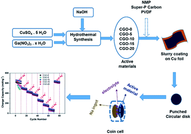
A copper precursor solution was prepared by adding 2.815558 g of copper sulphate pentahydrate (CuSO4·5 H2O) (purchased from Alfa Aesar, 99.9% pure) to 120 mL of double distilled water under magnetic stirring. Once a homogeneous solution was obtained, 0.225 M concentrated NaOH solution was mixed into the copper sulphate solution at room temperature. After obtaining a homogeneous solution upon magnetic stirring, the final pH of the solution was found to be 5, and the solution mixture was transferred into a 200 mL autoclave which was then heat treated at 100 °C for 5 h in a muffle furnace. After cooling the solution down naturally to room temperature, the ensuing blue coloured precipitate was filtered and washed with double distilled water and ethanol several times. The obtained precipitate was then dispersed in double distilled water and dried in a hot air oven at 75 °C overnight. The obtained powder sample was then calcined at 900 °C for 5 h to get black coloured copper oxide (CuO) powders whose chemical phase was confirmed through XRD analysis. To prepare the gallium copper oxide composites, gallium nitrate hydrate (Ga(NO3)3·xH2O) (purchased from Alfa Aesar, 99.9% pure) was added at 5, 10, 15 and 20 wt%, whereas CuSO4·5H2O was added at 95, 90, 85 and 80 wt%. Both the gallium and copper precursors were added in the appropriate weight percentages to double distilled water, and 0.225 M NaOH solution was added to this homogeneous precursor solution in all cases. The same synthesis procedure was followed for all weight ratios as described for pristine CuO synthesis. Post-calcination, the powder samples with Ga loaded at 0, 5, 10, 15 and 20 wt% were named as CGO-0, CGO-5, CGO-10, CGO-15 and CGO-20, respectively, and these codes are used to refer to them throughout this paper. Scheme 1 shows a schematic illustration containing the synthesis and cell design.2.2 Physical characterization
All the synthesized materials were structurally characterized using a Rigaku Ultima-III X-ray diffractometer with Cu-Kα radiation (λ = 1.5406 Å). Morphological and elemental analyses were carried out using a Carl Zeiss-Sigma Scanning Electron Microscope with EDAX provision. HRTEM (high resolution transmission electron microscope) images and SAED (selected area electron diffraction) patterns of CGO-10, before and after cycling, were obtained using a Jeol/JEM 2100 HRTEM. The composition and the oxidation states of different elements in CGO-10 were analyzed by X-ray photoelectron spectroscopy (XPS) with a scan range of 1200 eV. Surface area and pore size analyses of CGO-10 were carried out using N2 adsorption–desorption curves obtained by using the Brunauer–Emmett–Teller method, and the data were obtained on a Micrometrics ASAP 2010 Physisorption & Porosimetry system. Pore size distributions were obtained by employing BJH analysis on the desorption branch.2.3 Electrochemical characterization
The working electrode was prepared by using the traditional slurry coating method in which 80% synthesized active material was mixed with 10% super-P carbon and 10% PVDF binder. Here, super-P carbon acts as a conductive additive. N-methylpyrrolidone was used as a solvent to prepare the slurry homogeneously. The as-obtained homogeneous slurry was coated onto copper foil using an electrode coater and dried under ambient conditions. Circular discs of 18 mm diameter were punched out and dried under vacuum at 120 °C for 12 hours. 2032 type coin cells were finally assembled in an argon filled glove box in which the as-obtained disk was used as the working electrode and a sodium ingot was used as the reference electrode. The electrolyte was sodium perchlorate (NaClO4) in 1![[thin space (1/6-em)]](https://www.rsc.org/images/entities/char_2009.gif) :
:![[thin space (1/6-em)]](https://www.rsc.org/images/entities/char_2009.gif) 1 ethylene carbonate/diethyl carbonate (EC/DEC) (1
1 ethylene carbonate/diethyl carbonate (EC/DEC) (1![[thin space (1/6-em)]](https://www.rsc.org/images/entities/char_2009.gif) :
:![[thin space (1/6-em)]](https://www.rsc.org/images/entities/char_2009.gif) 1 v/v), and Celgard 2400 was used as a separator. The galvanostatic charge/discharge studies were carried out on a programmable battery tester (NEWARE battery analyzer) at various current densities within the potential window between 0.01 and 3 V. The cyclic voltammetry (CV) and electrochemical impedance spectroscopy (EIS) studies were carried out on an electrochemical workstation (SP-150, Biologic SAS, France). The CV studies were carried out between the potential limits of 0.01 and 3 V at a scan rate of 0.1 mV s−1. The EIS studies were carried out with an AC voltage signal of 5 mV and a frequency range between 100 kHz and 5 mHz.
1 v/v), and Celgard 2400 was used as a separator. The galvanostatic charge/discharge studies were carried out on a programmable battery tester (NEWARE battery analyzer) at various current densities within the potential window between 0.01 and 3 V. The cyclic voltammetry (CV) and electrochemical impedance spectroscopy (EIS) studies were carried out on an electrochemical workstation (SP-150, Biologic SAS, France). The CV studies were carried out between the potential limits of 0.01 and 3 V at a scan rate of 0.1 mV s−1. The EIS studies were carried out with an AC voltage signal of 5 mV and a frequency range between 100 kHz and 5 mHz.
3. Results and discussion
3.1 XRD analysis
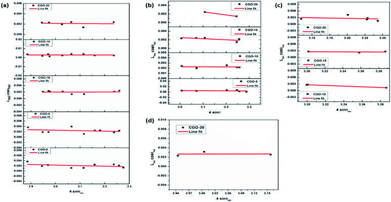
Samples of pure copper oxide and composites of copper and gallium oxides containing 5, 10, 15 and 20 wt% of gallium precursor (i.e., Ga(NO3)3·xH2O), calculated with respect to copper precursor (i.e., CuSO4·5H2O) weight, were structurally analysed by XRD. The obtained patterns of CGO-0, CGO-5, CGO-10, CGO-15 and CGO-20 are shown in Fig. 1. The phases of the synthesized samples matched well with the standards in the ICSD database. Through phase confirmation, it has been ascertained that there are four oxide phases of Cu and Ga found in the synthesized composites. They are CuO (copper oxide), copper gallium oxide (CuGa2O4), paramelaconite (Cu4O3) and gallium oxide (β-Ga2O3), which matched well with the ICSD standard patterns with reference numbers 01-080-1268, 00-044-0183, 01-083-1665 and 01-087-1901, and have monoclinic (space group: C2/c), cubic (space group: Fd3m), tetragonal (space group: I41/amd) and monoclinic (space group: C2/m) structures, respectively. CGO-0 showed diffraction peaks corresponding to CuO alone, whereas when the gallium precursor was introduced at 5 wt%, CGO-5 showed peaks for CuO and CuGa2O4. In addition to these two phases, CGO-10, CGO-15 and CGO-20 also showed peaks for the Cu4O3 phase, and CGO-20 exhibited peaks corresponding to Ga2O3 in addition to the prior mentioned oxide phases. The XRD patterns of all samples showed no traces of additional phases to the prior mentioned ones. The content of each phase was calculated as a percentage in terms of the ratio of the integral intensity of each phase over the sum of the integral intensities of all phases present in the sample, as reported in Table 1. The percentage of CuO phase was found to be 100%, 83.90%, 73.08%, 49.18% and 38.58% in CGO-0, CGO-5, CGO-10, CGO-15 and CGO-20, respectively. CGO-5 contained 16.10% CuGa2O4, whereas the CuGa2O4 content was found to be 22.90%, 27.25% and 6.59% in CGO-10, CGO-15 and CGO-20, respectively. The Cu4O3 content was estimated to be 4.02%, 23.57% and 39.25% in CGO-10, CGO-15 and CGO-20, respectively. The Ga2O3 phase has been found only in CGO-20, and its content has been found to be 15.59%. The presence of CuO decreased gradually with increasing Ga content from CGO-0 to CGO-20. Ga precipitated in the form of CuGa2O4 in CGO-5, CGO-10, CGO-15 and CGO-20, whereas in CGO-20, there is formation of Ga2O3 in addition to the CuGa2O4 phase, which shows that the abundance of Ga content in CGO-20 perturbed the equilibrium of CuGa2O4 phase formation which led to a favourable phase equilibrium for Ga2O3 and so lower probability for the formation of CuGa2O4. With an increase in Ga loading from 5 wt% to 10 wt%, Cu4O3 formation became more prominent. Cu4O3 started appearing in CGO-10 and the amount increased with Ga loading until CGO-20. As β-Ga2O3 is known to be a relatively electrochemically inactive phase,38 CGO-20 is speculated to show poor electrochemical anodic performance among all the samples owing to its relatively greater content of Ga2O3. It has been proved that both CuO and Cu4O3 are electrochemically active materials, and thus the presence of both of these phases may enhance the storage capability of the prepared composites. Thus, the presence of the novel phase CuGa2O4 plays a vital role in controlling the anodic activity of the material. It is expected that the CuGa2O4 phase is responsible for enhancing the anode material stability by means of buffering the structural collapse of the material that happens during electrochemical cycling. Based on this assumption, it is expected that the sodium-ion storage capability of CGO-5, CGO-10 and CGO-15 may be better than that of CGO-0 and CGO-20, owing to the CuGa2O4 content in them. Further, Cu4O3 was investigated as an anode material for LIBs and was shown to exhibit superior rate performance and lower polarization owing to its lower impedance than CuO.39 Thus, the collective and optimized proportional presence of the CuO, CuGa2O4 and Cu4O3 phases in the composites is expected to affect the electrochemical performance of the composites. The contribution of instrumental error to the broadening of the peaks is corrected by following eqn (1), where the full width at half maximum (FWHM) of the XRD peak profile of a Si standard is used for calibration purposes. In eqn (1),40,41Lobserved denotes the FWHM of the obtained XRD pattern, Linstrument is the FWHM of the standard reference peak profile, and Lhkl is the FWHM of the peak corresponding to the (hkl) crystalline plane after instrumental correction. The crystallite size and micro strain of each phase in each sample are found by following the Williamson–Hall (W–H) method (Fig. 2) in which line broadening in XRD is assumed to be the result of a cumulative effect of finite crystallite size and micro strain. Thus, in this analysis these two effects on peak broadening are de-convoluted and the final equation is given in eqn (2), where Lhkl represents the FWHM of the (hkl) plane, θhkl is the Bragg diffraction angle corresponding to the (hkl) peak orientation, k denotes the shape factor, λ is the wavelength of the X-rays, ε is the strain and D denotes the crystallite size.40,42–44 The W–H analytical method is considered to be an improved technique relative to Scherrer’s method of analysis, as the strain contribution to peak broadening is neglected in Scherrer’s equation.40–44 The corresponding equation for the Scherrer method is given in eqn (3). In eqn (3), all variables have their usual meaning as described earlier. The crystallite sizes and micro strain values of the various chemical phases that are present in all samples under investigation are tabulated and shown in Table 1. Negative values of micro strain represent compressive strain whereas positive values indicate tensile strain.| Lhkl = {(Lobserved2 − Linstrument2)}1/2 | (1) |
 | (2) |
 | (3) |
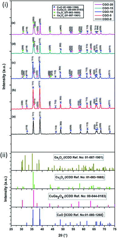 | ||
| Fig. 1 (i) XRD patterns of (a) CGO-0, (b) CGO-5, (c) CGO-10, (d) CGO-15, and (e) CGO-20; (ii) reference XRD patterns of CuO, CuGa2O4, Cu4O3 and Ga2O3. | ||
| Sample code | Phase | Crystal system | Lattice parameters | Crystallite size (nm) | Micro strain (×10−3) | |
|---|---|---|---|---|---|---|
| CGO-0 | CuO | Monoclinic | a (Å) | 4.7508 ± 0.0251 | 15.69 | −2.14 |
| b (Å) | 3.4328 ± 0.0284 | |||||
| c (Å) | 5.1985 ± 0.208 | |||||
| Beta (°) | 97.2681 ± 0.576 | |||||
| Unit cell volume V (Å)3 | 84.254 | |||||
| CGO-5 | CuO | Monoclinic | a (Å) | 4.7357 ± 0.2511 | 16.89 | −1.84 |
| b (Å) | 3.4181 ± 0.0379 | |||||
| c (Å) | 5.1741 ± 0.2039 | |||||
| Beta (°) | 98.08 ± 0.0578 | |||||
| Unit cell volume V (Å)3 | 82.922 | |||||
| CuGa2O4 | Cubic | a (Å) | 8.3269 ± 0.0200 | 7.04 | −4.67 | |
| Unit cell volume V (Å)3 | 577.369 | |||||
| CGO-10 | CuO | Monoclinic | a (Å) | 4.6905 ± 0.0053 | 81.62 | 0.11 |
| b (Å) | 3.4262 ± 0.0034 | |||||
| c (Å) | 5.1398 ± 0.0204 | |||||
| Beta (°) | 99.59 ± 0.18 | |||||
| Unit cell volume V (Å)3 | 81.446 | |||||
| CuGa2O4 | Cubic | a (Å) | 8.3066 ± 0.0060 | 50.41 | −0.15 | |
| Unit cell volume V (Å)3 | 573.143 | |||||
| Cu4O3 | Tetragonal | a (Å) | 5.8308 ± 0.0027 | 2.60 | −15.63 | |
| c (Å) | 9.9541 ± 0.0063 | |||||
| Unit cell volume V (Å)3 | 338.426 | |||||
| c/a | 1.7072 ± 0.0011 | |||||
| CGO-15 | CuO | Monoclinic | a (Å) | 4.6697 ± 0.0219 | 42.32 | −0.12 |
| b (Å) | 3.4166 ± 0.0043 | |||||
| c (Å) | 5.1344 ± 0.0107 | |||||
| Beta (°) | 99.56 ± 0.38 | |||||
| Unit cell volume V (Å)3 | 80.777 | |||||
| CuGa2O4 | Cubic | a (Å) | 8.2680 ± 0.055 | 13.43 | −2.56 | |
| Unit cell volume V (Å)3 | 565.208 | |||||
| Cu4O3 | Tetragonal | a (Å) | 5.8195 ± 0.002 | 18.04 | −1.57 | |
| c (Å) | 9.9524 ± 0.0052 | |||||
| Unit cell volume V (Å)3 | 336.25 | |||||
| c/a | 1.7106 ± 0.0021 | |||||
| CGO-20 | CuO | Monoclinic | a (Å) | 4.6919 ± 0.0102 | 40.93 | −0.40 |
| b (Å) | 3.4088 ± 0.0097 | |||||
| c (Å) | 5.0601 ± 0.0384 | |||||
| Beta (°) | 99.61 ± 0.20 | |||||
| Unit cell volume V (Å)3 | 79.96 | |||||
| CuGa2O4 | Cubic | a (Å) | 8.2145 ± 0.0015 | 5.50 | −7.23 | |
| Unit cell volume V (Å)3 | 559.16 | |||||
| Cu4O3 | Tetragonal | a (Å) | 5.8038 ± 0.0022 | 11.77 | −2.81 | |
| c (Å) | 9.9497 ± 0.0058 | |||||
| Unit cell volume V (Å)3 | 335.144 | |||||
| c/a | 1.7143 ± 0.0010 | |||||
| Ga2O3 | Monoclinic | a (Å) | 5.8002 ± 0.0015 | 58.85 | 0.11 | |
| b (Å) | 3.26814 ± 0.0016 | |||||
| c (Å) | 12.2508 ± 0.0010 | |||||
| Beta (°) | 103.98 ± 0.18 | |||||
| Unit cell volume V (Å)3 | 231.25 | |||||
The lattice parameters of the unit cells corresponding to different phases were obtained by refining and fitting the XRD peaks of the corresponding phases, and the obtained values are shown in Table 1. It can be found from Table 1 that the CuO phase in CGO-0 showed a crystallite size of 15.69 nm, which is its lowest size among all the other samples and is accompanied by a compressive micro strain of 2.14 × 10⁻³. The CuO phase showed crystallite sizes of 16.89, 81.62, 42.32 and 40.93 nm in CGO-5, CGO-10, CGO-15 and CGO-20, respectively. The crystallite sizes of CuGa2O4 in CGO-5, CGO-10, CGO-15 and CGO-20 are found to be 7.04, 50.41, 13.43 and 5.50 nm, respectively. The crystallite sizes of Cu4O3 are found to be 2.60, 18.04 and 11.77 nm in CGO-10, CGO-15 and CGO-20, respectively. Ga2O3, which existed only in CGO-20, was found to exhibit a crystallite size of 58.85 nm.
Naing et al.45 and Liao et al.46 showed that grain size enormously affects the electrochemical behavior of metal alloys. It has been proved that the coarser the crystallite, the better the rate performance, owing to larger grain boundary areas that allow diffusion of electrolyte ions through them, and finer crystallites in anode materials increase the cycle life, as they resist flow of electrolyte ions due to their narrower grain boundaries.47 As mentioned earlier, CuO and Cu4O3 are electrochemically active materials, whereas the presence of Ga either in the form of a ternary oxide, CuGa2O4, or as a binary oxide, Ga2O3, worsens the electrochemical performance due to the redox inactive behavior of Ga. However, the presence of Ga with Cu, i.e. CuGa2O4, in the anode material may increase the cycle life by providing a buffering effect against structural collapse or volume expansions that take place in the active matrix during charge/discharge cycles. Moreover, Cu4O3 has been proved to exhibit superior rate performance and capacity retention over CuO and Cu2O.39 Thus, considering the above factors and the crystallite sizes obtained from XRD, it can be assumed that the large crystallite size of CuO in CGO-10 can lead to an improvement in rate performance, but may reduce the cycle life due to the formation of a greater quantity of residual phases. But, the presence of an inactive phase, i.e. CuGa2O4, with relatively larger crystallite size, and the presence of Cu4O3 with relatively finer crystallite size may increase the cycle life of the CGO-10 anode material among all the samples. Although CGO-10 is expected to show superior rate performance and cycle stability, CGO-5, CGO-10 and CGO-15 are also expected to show enhanced anodic performance compared to CGO-0. CGO-20, owing to the presence of inactive Ga2O3, may exhibit relatively lower electrochemical performance.
3.2 Morphological studies
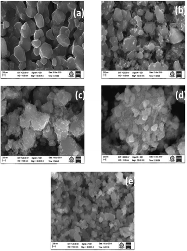
Morphological observations are carried out through SEM micrographs as shown in Fig. 3. It has been observed that CGO-0 showed a beach stone-like morphology with irregular particle shapes. It is clear from Fig. 3 that introduction of gallium into the system promoted the precipitation of Ga phases on top of the CuO particles observed in Fig. 3a. This accumulation of secondary phases is clearly visible in the figure as tiny particles covering the CuO particles, and the coverage of the beach stone-like particles by powder-like particles increased from CGO-5 to CGO-20. In CGO-15 and CGO-20, the Ga phases became dominant and covered almost all of the CuO particles, and the CuO particles became almost invisible under microscopic scanning. The aspect ratios of the CuO particles in all samples are calculated as the ratio between the length of the longest dimension (along the length) of the particle to the diameter along the shortest dimension (along the breadth), as the particles are irregular in shape. The calculated average aspect ratios for all samples are given in Table 2. The aspect ratios of the particles varied irregularly from sample-to-sample and can be correlated with the formation of different binary and ternary oxides of Cu and Ga (CuGa2O4, Cu4O3) and the strain associated with their formation. It is evident that particles with lower dimensions can show relatively enhanced electrochemical performance, and thus it can be presumed that CGO-10, owing to its lower aspect ratio, may exhibit better rate performance.| Sample no. | Sample code | Aspect ratio |
|---|---|---|
| 1 | CGO-0 | 1.33 |
| 2 | CGO-5 | 1.41 |
| 3 | CGO-10 | 1.19 |
| 4 | CGO-15 | 1.40 |
| 5 | CGO-20 | 1.63 |
Fig. 4 shows elemental analyses of the samples carried out through EDAX incorporated in the SEM. The atomic% and weight% of Cu, Ga and O are in accordance with the proportions of Cu and Ga precursors added. The Ga content increased with increasing Ga precursor wt%. Ga wt% in CGO-0, CGO-5, CGO-10, CGO-15 and CGO-20 are found to be 0 wt%, 7.2 wt%, 15.2 wt%, 22.7 wt% and 31.9 wt%, respectively. It can be said from these results that Ga incorporation into the base material was successfully carried out, and the deviation of these values from the added wt% of Ga is owing to the fact that the added wt% is based on the amounts of precursor salts used, not on the actual Ga content.
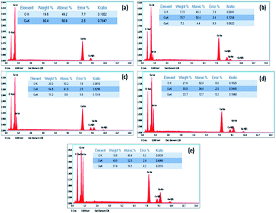 | ||
| Fig. 4 EDAX plots with quantitative elemental analysis of (a) CGO-0, (b) CGO-5, (c) CGO-10, (d) CGO-15 and (e) CGO-20. | ||
TEM micrographs of CGO-10 are shown in Fig. 5. These micrographs are consistent with those from SEM analysis. Fig. 5a clearly depicts small particles of Cu4O3 and CuGa2O4 on top of bigger particles of CuO. Fig. 5b is a magnified portion of the smaller particle aggregates, and their particle sizes varied in the range of 30–85 nm. An HRTEM image and the SAED pattern of CGO-10 are shown in Fig. 5c and d, respectively. Lattice fringes are clearly observed in CGO-10, in which the (220) diffraction planes corresponding to Cu4O3 and CuGa2O4 have d-spacings of 0.206 and 0.293 nm, respectively. Well defined bright spots formed into rings are observed in the SAED pattern, which shows that these samples are polycrystalline and the grains are monocrystalline. In the SAED pattern of CGO-10, the spots designated as a, b and c correspond to the CuO, CuGa2O4 and Cu4O3 phases and were assigned to the (![[1 with combining macron]](https://www.rsc.org/images/entities/char_0031_0304.gif) 12), (220) and (200) planes with d-spacings of 0.196, 0.293 and 0.290 nm, respectively. All the d-spacing values found from the SAED pattern of CGO-10 are in good agreement with those found from the corresponding XRD pattern.
12), (220) and (200) planes with d-spacings of 0.196, 0.293 and 0.290 nm, respectively. All the d-spacing values found from the SAED pattern of CGO-10 are in good agreement with those found from the corresponding XRD pattern.
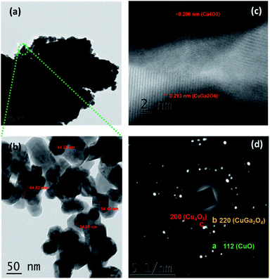 | ||
| Fig. 5 TEM micrographs of CGO-10 at different magnifications: (a) 200 nm; (b) 50 nm; (c) HRTEM image and (d) SAED pattern of CGO-10. | ||
3.3 BET analysis
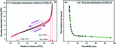
The surface area of CGO-10 was obtained from BET N2 adsorption–desorption studies. The N2 adsorption–desorption profiles of CGO-10 are shown in Fig. 6a, and the corresponding pore size distribution is shown in Fig. 6b. As shown in Fig. 6a, CGO-10 showed a type-III isotherm for both the adsorption and desorption processes with an H3 type hysteresis loop according to the IUPAC classification.46,47 H3 type hysteresis is a characteristic of meso sized pores, and the narrow loop appeared with a lower limit of p/p0 = 0.16 up to p/p0 = 0.94, exhibiting the dominance of mesoporosity in the sample. Also, a short and narrow loop appeared at high relative pressures between p/p0 = 0.94 and p/p0 = 0.99, which corresponds to a small amount of nearly macro sized pores. Fig. 6b shows the pore volume distribution as a function of pore width. The surface area of CGO-10 has been obtained from the N2 adsorption–desorption profile by following the BET (Brunauer–Emmett–Teller) method, and the value was found to be 11.5171 m2 g−1. The average pore diameter was obtained by employing the BJH (Barrett–Joyner–Halenda) analytical method on the desorption branch, and the pore diameter was found to be 5.2015 nm. The formation of pores on the particle surface may be due to the liberation of water and hydroxyl ions during calcination.48,493.4 XPS analysis
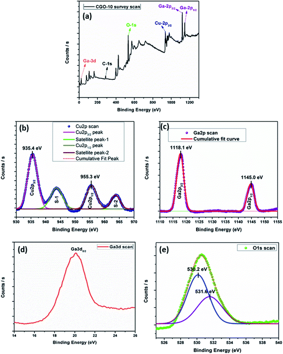
Investigations of the chemical bonding states of different elements in the CGO-10 sample are carried out through X-ray photoelectron spectroscopy (XPS). The XPS survey spectrum showed the presence of Cu, Ga and O in the sample (Fig. 7a). The XPS peaks of the elements mentioned above were de-convoluted using the Gaussian fitting function. The Cu-2p (Fig. 7b) scan exhibited four peaks among which two are satellite peaks and designated as S-1 and S-2 centred at 943.6 eV and 963.7 eV, respectively.50 The Cu-2p scan also showed two strong photoelectron emissions de-convoluted at 935.4 eV and 955.3 eV, corresponding to the Cu-2p3/2 and Cu-2p1/2 electronic levels, respectively.51,52 These are the characteristic peaks of Cu(II), and the Cu2+ oxidized charge state in CuGa2O4 exhibited a spin–orbit splitting energy separation of 19.9 eV which matched the previously reported values well.51–54 The Ga-2p scan showed two peaks centred at 1118.18 eV and 1145.08 eV corresponding to Ga-2p3/2 and Ga-2p1/2, respectively, as shown in Fig. 7c51, with an energy separation of 26.9 eV which matched the previously reported value well.51,54,55 The Ga-3d scan shown in Fig. 7d exhibits a peak at around 20.08 eV corresponding to Ga-3d5/2.56–58 The O-1s XPS scan is shown in Fig. 7e and has two de-convoluted peaks, one centered at 530.2 eV that corresponds to metal–oxygen bonding,52,59 and the other one at 531.6 eV, corresponding to surface absorbed O2.60 The slight shift of the O-1s peak towards higher binding energy than the reported values may be due to an interaction between the binary and ternary oxide phases present in the sample.61 The observation of all the above described peaks in the sample gives evidence for the presence of CuO and CuGa2O4 in CGO-10.3.5 Charge/discharge studies
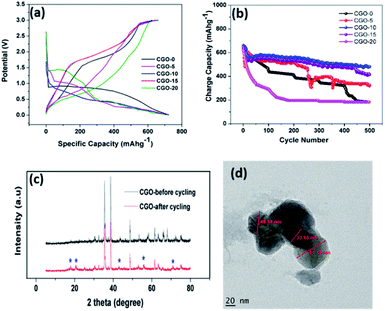
In order to investigate the sodium storage behaviour of the CGO composites we examined the galvanostatic charge/discharge behaviour at 0.07 A g−1 between the potential limits 0.01 and 3 V. Fig. 8a presents the first charge/discharge curves of the CGO composites in which the composites delivered charge capacities of 624, 640, 661, 647 and 618 mA h g−1 for CGO-0, CGO-5, CGO-10, CGO-15 and CGO-20, respectively. The charge/discharge profiles of the composites vary from that of pristine CuO which indicates that Cu4O3 also participated in the electrochemical reaction of CuO for sodium-ion storage. It is interesting to note that though the charge/discharge profiles of CGO-10 and CGO-15 are identical, likewise the profiles of CGO-5 and CGO-20, all deviate from that of pristine CuO. The deviation is due to the formation of Cu4O3, CuGa2O4 and Ga2O3 phases in the composites. However, the content of the phases varied when the amount of Ga in the composites was increased from 5 to 20 wt%. Pristine CuO exhibited broad plateaus at around 0.82–0.5 V and 1.7–2.1 V in the discharge and charge curves, respectively. The broad plateau in the discharge curve represents the multiple reduction processes involved in solid–electrolyte interphase (SEI) formation on the electrode surface: intermediate CuII1−xCuIxO1−x/2 phase formation, generation of the Cu2O phase and the decomposition of Cu2O to Cu and Na2O. Similarly, the broad plateau in the charge profile indicates the reverse reaction of the discharge process. The composites exhibit three plateaus, viz. 0.3–0.14, 0.8–0.4 and 1.4–0.9 V in the discharge curve and three plateaus, viz. 0.4–0.78, 0.9–1.6 and 1.7–2.7 V in the charge curve. The three reduction plateaus of the composites are due to the intermediate phase formation of CuII1−xCuIxO1−x/2 and SEI film formation, reduction of CuO to Cu2O and further conversion of Cu2O to Cu. The oxidation peaks correspond to the decomposition of the SEI film, the oxidation process of Cu to Cu2O and further oxidation of Cu2O to CuO. The three plateaus in the charge and discharge profiles are obtained at slightly different potentials for all the composites, which can be attributed to the variation in content of the Cu4O3, CuGa2O4 and Ga2O3 phases in different composites. The contents of the electrochemically active Cu4O3 and CuGa2O4 phases are higher in CGO-10 and CGO-15 but they are lower in CGO-5 and CGO-20. In CGO-5 and CGO-20, the electrochemically inactive β-Ga2O3 phase dominates the electrochemical process during cycling. The high capacities of CGO-10 and CGO-15 may be ascribed to the fact that the electrochemically active Cu4O3 phase39,62 together with the CuGa2O4 phase enhances the capacity of the CuO phase. The Cu4O3 phase is also present in the case of CGO-5 and CGO-20, however, the content of CuGa2O4 is very low and there is more Ga2O3 in CGO-20 (β-Ga2O3 is known to be redox inactive38). Here, the CuGa2O4 phase may act as a matrix to enhance the capacity of CuO during electrochemical reactions.
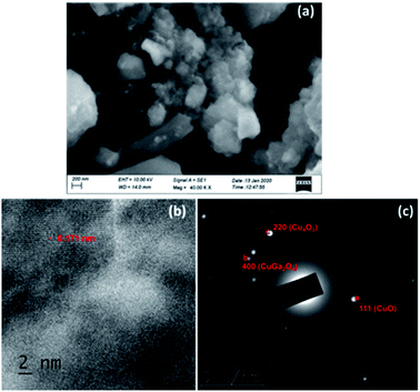
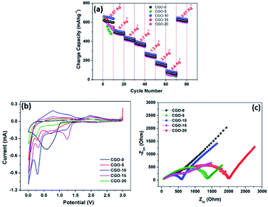
Fig. 8b depicts the cycling performance of the CGO composites at a current density of 0.07 A g−1 over 500 cycles. The first cycle charge capacities are 624, 640, 661, 647 and 618 mA h g−1 for CGO-0, CGO-5, CGO-10, CGO-15 and CGO-20, respectively, whereas at the 500th cycle the obtained charge capacities are 183, 319, 481, 415 and 183 mA h g−1, respectively. The corresponding capacity retentions are 29.3, 49.8, 73.1, 64.1 and 29.6%, respectively. The obtained cycling performance clearly indicates that the cycling stability of CuO is greatly enhanced by the electrochemically active Cu4O3 phase together with the CuGa2O4 matrix. The inferior performance of CGO-0, CGO-5 and CGO-20 is attributed to large volume expansion15 during the electrochemical reaction which resulted in loss of contact between the current collector and the electrode material. In order to investigate the stability of the electrode material after 500 cycles, we carried out ex situ XRD (Fig. 8c), TEM (Fig. 8d), ex situ SEM (Fig. 9a) and HRTEM (Fig. 9b and c) on the CGO-10 electrode. Interestingly, the structure and morphology of CGO-10 are well maintained even after 500 cycles. The ex situ XRD pattern of CGO-10 after cycling showed the characteristic peaks of CGO-10 with minor impurity peaks which may be due to the conductive carbon and binder used for the electrode coating. TEM and SEM images of CGO-10 after cycling are shown in Fig. 8d and 9a, respectively. There is no noticeable change in particle morphology and size even after prolonged cycling of the material. An HRTEM image of CGO-10 after cycling and the corresponding SAED pattern are shown in Fig. 9b and c, respectively. Lattice fringes are clearly observed in CGO-10 after cycling, and the (020) plane of CuO with a d-spacing of 0.171 nm is clearly observed in the HRTEM image of CGO-10 after cycling (from Fig. 9b). The well defined bright spots formed into rings in the diffraction pattern are attributed to the polycrystalline sample and the monocrystalline grains. The spots labelled a, b and c in the SAED pattern of CGO-10 after cycling are assigned to the (![[1 with combining macron]](https://www.rsc.org/images/entities/char_0031_0304.gif) 11), (400) and (220) diffraction planes corresponding to the CuO, CuGa2O4 and Cu4O3 phases with d-spacing values of 0.253, 0.207 and 0.206 nm, respectively. All the d-spacing values found from the SAED pattern of CGO-10 after cycling are in good agreement with those found from the corresponding XRD pattern. The above obtained results confirmed that the charge/discharge behaviour and cycling stability of the CuO material are greatly enhanced by the Cu4O3 phase and the CuGa2O4 matrix. The rate capability of the CuO/Ga2O3 composites was investigated between the potential limits of 0.01 and 3 V at different current densities, as shown in Fig. 10a. Compared to the other composites, the CGO-10 composite exhibits better rate capability, with charge capacities of 661, 519, 447, 401, 281, 187 and 96 mA h g−1 at current densities of 0.07, 0.1, 0.3, 0.7, 1.3, 3.3 and 6.6 A g−1, respectively. It is interesting to note that the cell exhibited a charge capacity of 647 mA h g−1 when the cell is cycled back from high current density to low current density (0.07 A g−1). The rate capability results confirmed that CGO-10 exhibits good rate performance and structural stability at high current densities. Aside from CGO-10, the other composites exhibited poor rate performance at high current densities. The obtained capacities and cycling stability are superior compared to previous literature.27,63 In order to further understand the electrochemical reactions of the CGO composites, we carried out cyclic voltammetry studies (Fig. 10b) at a scan rate of 0.1 mV s−1 between the potential limits of 0.01 and 3 V. The cyclic voltammograms are quite consistent with the charge/discharge behaviour of the CGO composites. The cathodic peak was observed at 0.57 V and the anodic peak was observed at 1.95 V for the pristine CuO material. The broad cathodic peak corresponds to multiple reduction processes involved in the decomposition of the electrolyte solvents, i.e. EC and DEC, to form a SEI film on the electrode surface, the formation of an intermediate CuO phase, i.e. CuII1−xCuIxO1−x/2, the generation of the Cu2O phase and the decomposition of Cu2O to Cu and Na2O. During the charge process, a broad oxidation peak is observed at around 1.82 V, which corresponds to the oxidation process involved in the formation of the CuO phase from the Cu2O phase. The obtained CV curve of CuO is quite consistent with the previously reported literature.28 All the composites exhibited three reduction peaks, viz. 1.23, 0.7 and 0.28 V, during discharge and three oxidation peaks at 0.78, 1.28 and 1.98 V during charge. Like the charge/discharge profiles, the CV curves of CGO-10 and CGO-15 are quite similar, while those of CGO-5 and CGO-20 appear to be similar except for the redox peak intensities. The obtained CV profiles of the CGO composites are in accordance with the previously reported literature.27 The highest capacities of the CGO composites are attributed to the combined redox reactions of CuO and Cu4O3, as we couldn’t identify the peak signatures separately since Cu4O3 also forms a 2CuO + Cu2O composite which itself exhibits several redox peaks according to L. Zhao et al.,62 and the mechanism of storing lithium ions is still not clear. From the CV profiles we clearly confirmed that only the CuO and Cu4O3 phases are involved in the redox reactions, however the CuGa2O4 phase acts as an inactive matrix to stabilize the CuO phase during cycling.
11), (400) and (220) diffraction planes corresponding to the CuO, CuGa2O4 and Cu4O3 phases with d-spacing values of 0.253, 0.207 and 0.206 nm, respectively. All the d-spacing values found from the SAED pattern of CGO-10 after cycling are in good agreement with those found from the corresponding XRD pattern. The above obtained results confirmed that the charge/discharge behaviour and cycling stability of the CuO material are greatly enhanced by the Cu4O3 phase and the CuGa2O4 matrix. The rate capability of the CuO/Ga2O3 composites was investigated between the potential limits of 0.01 and 3 V at different current densities, as shown in Fig. 10a. Compared to the other composites, the CGO-10 composite exhibits better rate capability, with charge capacities of 661, 519, 447, 401, 281, 187 and 96 mA h g−1 at current densities of 0.07, 0.1, 0.3, 0.7, 1.3, 3.3 and 6.6 A g−1, respectively. It is interesting to note that the cell exhibited a charge capacity of 647 mA h g−1 when the cell is cycled back from high current density to low current density (0.07 A g−1). The rate capability results confirmed that CGO-10 exhibits good rate performance and structural stability at high current densities. Aside from CGO-10, the other composites exhibited poor rate performance at high current densities. The obtained capacities and cycling stability are superior compared to previous literature.27,63 In order to further understand the electrochemical reactions of the CGO composites, we carried out cyclic voltammetry studies (Fig. 10b) at a scan rate of 0.1 mV s−1 between the potential limits of 0.01 and 3 V. The cyclic voltammograms are quite consistent with the charge/discharge behaviour of the CGO composites. The cathodic peak was observed at 0.57 V and the anodic peak was observed at 1.95 V for the pristine CuO material. The broad cathodic peak corresponds to multiple reduction processes involved in the decomposition of the electrolyte solvents, i.e. EC and DEC, to form a SEI film on the electrode surface, the formation of an intermediate CuO phase, i.e. CuII1−xCuIxO1−x/2, the generation of the Cu2O phase and the decomposition of Cu2O to Cu and Na2O. During the charge process, a broad oxidation peak is observed at around 1.82 V, which corresponds to the oxidation process involved in the formation of the CuO phase from the Cu2O phase. The obtained CV curve of CuO is quite consistent with the previously reported literature.28 All the composites exhibited three reduction peaks, viz. 1.23, 0.7 and 0.28 V, during discharge and three oxidation peaks at 0.78, 1.28 and 1.98 V during charge. Like the charge/discharge profiles, the CV curves of CGO-10 and CGO-15 are quite similar, while those of CGO-5 and CGO-20 appear to be similar except for the redox peak intensities. The obtained CV profiles of the CGO composites are in accordance with the previously reported literature.27 The highest capacities of the CGO composites are attributed to the combined redox reactions of CuO and Cu4O3, as we couldn’t identify the peak signatures separately since Cu4O3 also forms a 2CuO + Cu2O composite which itself exhibits several redox peaks according to L. Zhao et al.,62 and the mechanism of storing lithium ions is still not clear. From the CV profiles we clearly confirmed that only the CuO and Cu4O3 phases are involved in the redox reactions, however the CuGa2O4 phase acts as an inactive matrix to stabilize the CuO phase during cycling.
In order to gain further insight into the charge/discharge profiles and CV curves of pristine CuO and CGO composites, we carried out EIS analysis and obtained Nyquist plots which are shown in Fig. 10c. The EIS parameters are listed in Table 3. All Nyquist plots show one semicircle in the high frequency region and a line inclined at 45° in the low frequency region, which is called the Warburg region. This Warburg region is a signature of the Na+ ion diffusion process occurring in the electrode material during cycling. Depressed semicircles are observed in the case of CGO-10 and CGO-15, whereas the other CGO composites exhibit semicircles with high Rct (Table 3). This indicates that CGO-10 and CGO-15 exhibit lower impedance as compared to the other CGO composites. From the electrochemical studies we clearly confirmed that the enhanced electrochemical performances of the CGO composites are mainly attributed to the presence of Cu4O3 and CuGa2O4 phases, in which the Cu4O3 phase is actively involved in the redox reactions and the CuGa2O4 phase stabilizes the CuO phase by buffering the volume expansion of CuO during cycling.
| Sample no. | Sample | R s (Ω) | R ct (Ω) | C dl (mF) |
|---|---|---|---|---|
| 1 | CGO-0 | 163 | 490 | 20 |
| 2 | CGO-5 | 47 | 1323 | 48 |
| 3 | CGO-10 | 101 | 516 | 72 |
| 4 | CGO-15 | 83 | 772 | 61 |
| 5 | CGO-20 | 324 | 1692 | 21 |
4. Conclusion
In summary, we have fabricated CGO composites with different weight percentages of Ga through a simple hydrothermal method. The HRTEM images and SAED patterns confirmed that the particle size varies from 30 to 85 nm and also showed that the Cu4O3 and CuGa2O4 phases reside on the surface of the CuO phase. The composites exhibit significantly improved capacity and capacity retention as compared to the pure CuO phase at a current density of 0.07 A g−1. The CGO-10 composite (CuO with 10 wt% Ga) exhibited the highest charge capacity of 481 mA h g−1 with capacity retention of 73.1% at a current density of 0.07 A g−1 over 500 cycles. The improved capacity and capacity retention of the composites are mainly attributed to the Cu4O3 phase as well as the CuGa2O4 phase, in which Cu4O3 effectively reduces the charge-transfer resistance and the CuGa2O4 phase buffers the volume expansion of the CuO particles during cycling. The obtained results demonstrate that the composites are considered as promising anode materials for sodium-ion batteries.Conflicts of interest
There are no conflicts to declare.Acknowledgements
One of the authors, Dr C. Nithya, wishes to thank the Department of Science and Technology (DST, India) for a Women Scientist Award (SR/WOS-A/CS-20/2017).References
- B. Dunn, H. Kamath and J. M. Tarascon, Electrical Energy Storage for the Grid: A Battery of Choices, Science, 2011, 334, 928 CrossRef CAS PubMed.
- Y. You and A. Manthiram, Progress in High-Voltage Cathode Materials for Rechargeable Sodium-Ion Batteries, Adv. Energy Mater., 2018, 8, 1701785 CrossRef.
- B. Guo, M. Niu, X. Lai and L. Chen, Application research on large-scale battery energy storage system under Global Energy Interconnection framework, Global Energy Interconnection, 2018, vol. 1, p. 79 Search PubMed.
- B. H. Rao, S. L. Arun and M. P. Selvan, Framework of Locality Electricity Trading System for Profitable Peer-to-Peer Power Transaction in Locality Electricity Market, IET Smart Grid, 2019 DOI:10.049/iet-stg.2019.0131.
- B. H. Rao, S. L. Arun and M. P. Selvan, An electric power trading framework for smart residential community in smart cities, IET Smart Cities, 2019, 1, 40, DOI:10.1049/iet-smc.2019.0055.
- W. Zhang, Z. X. Chi, W. X. Mao, R. W. Lv, A. M. Cao and L. J. Wan, One-Nanometer Precision Control of Al2O3 Nanoshells through a Solution-Based Synthesis Route, Angew. Chem., Int. Ed., 2014, 53, 12776 CrossRef CAS PubMed.
- P. F. Wang, H. R. Yao, X. Y. Liu, J. N. Zhang, L. Gu, X. Q. Yu, Y. X. Yin and Y. G. Guo, Ti-substituted NaNi0.5Mn0.5−xTixO2 Cathodes with Reversible O3-P3 Phase Transition for High Performance Sodium-Ion Batteries, Adv. Mater., 2017, 29, 1700210 CrossRef PubMed.
- L. Mu, S. Xu, Y. Li, Y. S. Hu, H. Li, L. Chen and X. Huang, Prototype Sodium-Ion Batteries Using an Air-Stable and Co/Ni-Free O3-Layered Metal Oxide Cathode, Adv. Mater., 2015, 27, 6928 CrossRef CAS PubMed.
- R. Y. Wang, C. D. Wessells, R. A. Huggins and Y. Cui, Highly Reversible Open Framework Nanoscale Electrodes for Divalent Ion Batteries, Nano Lett., 2013, 13, 5748 CrossRef CAS.
- C. Fang, Y. Huang, W. Zhang, J. Han, Z. Deng, Y. Cao and H. Yang, Routes to High Energy Cathodes of Sodium-Ion Batteries, Adv. Energy Mater., 2016, 6, 1501727 CrossRef.
- J. Y. Hwang, S. T. Myung and Y. K. Sun, Sodium-ion batteries: present and future, Chem. Soc. Rev., 2017, 46, 3529 RSC.
- H. Kim, H. Kim, Z. Ding, M. H. Lee, K. Lim, G. Yoon and K. Kang, Recent Progress in Electrode Materials for Sodium-Ion Batteries, Adv. Energy Mater., 2016, 6, 1600943 CrossRef.
- D. Kundu, E. Talaie, V. Duffort and L. F. Nazar, The Emerging Chemistry of Sodium Ion Batteries for Electrochemical Energy Storage, Angew. Chem., Int. Ed., 2015, 54, 3431 CrossRef CAS PubMed.
- Y. Zhao, L. P. Wang, M. T. Sougrati, Z. Feng, Y. Leconte, A. Fisher, M. Srinivasan and Z. Xu, A Review on Design Strategies for Carbon Based Metal Oxides and Sulfides Nanocomposites for High Performance Li and Na Ion Battery Anodes, Adv. Energy Mater., 2017, 7, 1601424 CrossRef.
- L. Wang, Z. Wei, M. Mao, H. Wang, Y. Li and J. Ma, Metal oxide/graphene composite anode materials for sodium-ion batteries, Energy Storage Materials, 2019, 16, 434 CrossRef.
- S. W. Kim, D. H. Seo, X. Ma, G. Ceder and K. Kang, Electrode Materials for Rechargeable Sodium-Ion Batteries: Potential Alternatives to Current Lithium-Ion Batteries, Adv. Energy Mater., 2012, 2, 710 CrossRef CAS.
- H. Pan, Y. S. Hu and L. Chen, Room-temperature stationary sodium-ion batteries for large-scale electric energy storage, Energy Environ. Sci., 2013, 6, 2338 RSC.
- J. Ma, Z. Wei, L. Wang, M. Zhuo, W. Ni and H. Wang, Layered Tin Sulfide and Selenide Anode Materials for Li- and Na-ion Batteries, J. Mater. Chem. A, 2018 10.1039/C8TA02695E.
- Y. Jiang, G. Zou, H. Hou, J. Li, C. Liu, X. Qiu and X. Ji, Composition Engineering Boosts Voltage Windows for Advanced Sodium-Ion Batteries, ACS Nano, 2019, 13, 10787, DOI:10.1021/acsnano.9b05614.
- Y. Zhang, C. Liu, Xu Gao, Z. Luo, J. Hu, G. Zou, H. Hou, Z. Xu and X. Ji, Revealing the activation effects of high valence cobalt in CoMoO4 towards highly reversible conversion, NanoEnergy, 2020, 68, 104333, DOI:10.1016/j.nanoen.2019.104333.
- W. Guo, W. Sun and Y. Wang, Multi-Layer CuO@NiO Hollow Spheres: Microwave-Assisted Metal-Organic-Framework Derivation and Highly Reversible Structure-Matched Stepwise Lithium Storage, ACS Nano, 2015, 9, 11462 CrossRef CAS PubMed.
- D. Yin, G. Huang, Z. Na, X. Wang, Q. Li and L. Wang, CuO Nanorod Arrays Formed Directly on Cu Foil from MOFs as Superior Binder-Free Anode Material for Lithium-Ion Batteries, ACS Energy Lett., 2017, 2, 1564 CrossRef CAS.
- F. Klein, R. Pinedo, B. B. Berkes, J. Janek and P. Adelhelm, Kinetics and Degradation Process of CuO as Conversion Electrode for Sodium-Ion Batteries: An Electrochemical study combined with Pressure Monitoring and DEMS, J. Phys. Chem. C, 2017, 121, 8679 CrossRef CAS.
- L. Zhang, Y. Wang, D. Xie, Y. Tang, C. Wu, L. Cui, Y. Li, X. Ning and Z. Shan, In situ transmission electron microscopy study of the electrochemical sodiation process for a single CuO nanowire electrode, RSC Adv., 2016, 6, 11441 RSC.
- F. Klein, R. Pinedo, P. Hering, A. Polity, J. Janek and P. Adelhelm, Reaction Mechanism and Surface Film Formation of Conversion Materials for Lithium- and Sodium-Ion Batteries: A XPS Case Study on Sputtered Copper Oxide (CuO) Thin Film Model Electrodes, J. Phys. Chem. C, 2016, 120, 1400 CrossRef CAS.
- P. C. Rath, J. Patra, D. Saikia, M. Mishra, J. Chang and H. Kao, Highly enhanced electrochemical performance of ultrafine CuO nanoparticles confined in ordered mesoporous carbons as anode materials for sodium-ion batteries, J. Mater. Chem. A, 2016, 4, 14222 RSC.
- D. Li, D. Yan, X. Zhang, J. Li, T. Lu and L. Pan, Porous CuO/reduced graphene oxide composites synthesized from metal–organic frameworks as anodes for high-performance sodium-ion batteries, J. Colloid Interface Sci., 2017, 497, 350 CrossRef CAS PubMed.
- L. Wang, K. Zhang, Z. Hu, W. Duan, F. Cheng and J. Chen, Porous CuO nanowires as the anode of rechargeable Na-ion batteries, Nano Res., 2014, 7, 199 CrossRef CAS.
- Y. Liu, Y. Qiao, W. X. Zhang, P. Hu, C. J. Chen, Z. Li, L. X. Yuan, X. L. Hu and Y. H. Huang, Facile fabrication of CuO nanosheets on Cu substrate as anode materials for electrochemical energy storage, J. Alloys Compd., 2014, 586, 208 CrossRef CAS.
- S. Yuan, X. L. Huang, D. L. Ma, H. G. Wang, F. Z. Meng and X. B. Zhang, Engraving Copper Foil Give Large-Scale Binder-Free Porous CuO Arrays for a High-Performance Sodium-Ion Battery Anode, Adv. Mater., 2014, 26, 2273 CrossRef CAS PubMed.
- A. Kim, M. K. Kim, K. Cho, J. Woo, Y. Lee, S. Han, D. Byun, W. Choi and J. K. Lee, One-Step Catalytic Synthesis of CuO/CuO in Graphitized Porous Carbon Matrix Derived from the Cu-based Metal–Organic Framework for Li- and Na-Ion Batteries, ACS Appl. Mater. Interfaces, 2016, 8, 19514 CrossRef CAS PubMed.
- X. Wang, Y. Liu, Y. Wang and L. Jiao, CuO Quantum Dots Embedded in Carbon Nanofibers as Binder-Free Anode for Sodium Ion Batteries with Enhanced Properties, Small, 2016, 12, 4865 CrossRef CAS PubMed.
- S. Cho, Y.-k. Ahn, Z. Yin, D.-J. You, H. Kim, Y. Piao, J. Yoo and Y. S. Kim, Novel synthesis of Copper oxide/graphite composite for high performance rechargeable battery anode, DOI:10.1002/chem.201701931.
- J. Yang, M. Winter and J. O. Besenhard, Small particle size multiphase Li-alloy anodes for lithium-ion-batteries, Solid State Ionics, 1996, 90, 281 CrossRef CAS.
- R. A. Huggins and B. A. Boukamp, US Pat., 4436796, 1984.
- P. Roy and S. K. Srivastava, Nanostructured anode materials for lithium ion batteries, J. Mater. Chem. A, 2015, 3, 2454 RSC.
- M. V. Reddy, G. V. Subba Rao and B. V. R. Chowdari, Metal Oxides and Oxysalts as Anode Materials for Li Ion Batteries, Chem. Rev., 2013, 113, 5364 CrossRef CAS PubMed.
- B. N. Ganguly, V. Verma, D. Chatterjee, B. Satpati, S. Debnath and P. Saha, Study of Gallium Oxide Nanoparticles Conjugated with β-cyclodextrin – An Application to Combat Cancer, ACS Appl. Mater. Interfaces, 2016, 8, 17127 CrossRef CAS PubMed.
- L. Zhao, H. Chen, Y. Wang, H. Che, P. Gunawan, Z. Zhong, H. Li and F. Su, Facile Solvothermal Synthesis of Phase-Pure Cu4O3 Microspheres and Their Lithium Storage Properties, Chem. Mater., 2012, 24, 1136 CrossRef CAS.
- A. Khorsand Zak, W. H. A. Majid, M. E. Abrishami and R. Yousefi, X-ray analysis of ZnO nanoparticles by Williamson–Hall and size–strain plot methods, Solid State Sci., 2011, 13, 251 CrossRef CAS.
- K. D. Rogers and P. Daniels, An X-ray Diffraction study of the effects of heat treatment on bone mineral microstructure, Biomaterials, 2002, 23, 2577 CrossRef CAS PubMed.
- Y. T. Prabhu, K. V. Rao, V. S. S. Kumar and B. S. Kumari, X-Ray Analysis by Williamson–Hall and Size–Strain Plot Methods of ZnO Nanoparticles with Fuel Variation, World J. Nano Sci. Eng., 2014, 4, 21 CrossRef CAS.
- C. Suranarayana and M. G. Norton, X-Ray Diffraction: A Practical Approach, Springer, New York, 1998 Search PubMed.
- R. Srinivasan, N. Rajeswari Yogamalar, R. Justin Joseyphus and A. Chandra Bose, Estimation of Lattice Strain, Stress, Energy Density and Crystallite size of the Spherical Yttrium Oxide Nanoparticles, Funct. Mater. Lett., 2009, 2, 131 CrossRef CAS.
- N. N. Aung and W. Zhou, Effect of grain size and twins on corrosion behaviour of AZ31B magnesium alloy, Corros. Sci., 2010, 52, 589 CrossRef CAS.
- J. Liao, M. Hotta and N. Yamamoto, Corrosion behavior of fine-grained AZ31B magnesium alloy, Corros. Sci., 2012, 61, 208 CrossRef CAS.
- Y. Domi, H. Usui, K. Sugimoto and H. Sakaguchi, Effect of Silicon Crystallite Size on its Electrochemical Performance for Lithium-Ion Batteries, Energy Technol., 2019 DOI:10.1002/ente.201800946.
- M. Thommes, K. Kaneko, A. V. Neimark, J. P. Olivier, F. Rodriguez-Reinoso, J. Rouquerol and K. S. W. Sing, Physisorption of gases, with special reference to the evaluation of surface area and pore size distribution (IUPAC Technical Report), Pure Appl. Chem., 2015, 87, 1051 CAS.
- K. S. W. Sing, D. H. Everett, R. A. W. Haul, L. Moscou, R. A. Pieroti, J. Rouquerol and T. Siemieniewska, Reporting Physisorption data for Gas/Solid Systems with Special Reference to the Determination of Surface Area and Porosity, Pure Appl. Chem., 1985, 57, 603 CAS.
- M. Orita, H. Ohta and M. Hirano, Deep-ultraviolet transparent conductive β-Ga2O3 thin films, Appl. Phys. Lett., 2000, 77, 4166 CrossRef CAS.
- A. M. Zardkhoshoui and S. S. H. Davarani, Designing a flexible all-solid-state supercapacitor based on CuGa2O4 and FeP–rGO electrodes, J. Alloys Compd., 2019, 773, 527 CrossRef CAS.
- A. A. Ensafi, S. E. Moosavifard, B. Rezaei and S. Kamari Kaverlavani, Engineering onion-like nanoporous CuCo2O4 hollow spheres derived from bimetal–organic frameworks for high-performance asymmetric supercapacitors, J. Mater. Chem. A, 2018, 6, 10497 RSC.
- S. Kamari Kaverlavani, S. E. Moosavifard and A. Bakouei, Self-templated synthesis of uniform nanoporous CuCo2O4 double-shelled hollow microspheres for high-performance asymmetric supercapacitors, Chem. Commun., 2017, 53, 1052 RSC.
- H. Wei, Z. Chen, Z. Wu, W. Cui, Y. Huang and W. Tang, Epitaxial growth and characterization of CuGa2O4 films by laser molecular beam epitaxy, AIP Adv., 2017, 7, 115216 CrossRef.
- D. Liu, X. Mo, K. Li, Y. Liu, J. Wang and T. Yang, The performance of spinel bulk-like oxygen-deficient CoGa2O4 as an air-cathode catalyst in microbial fuel cell, J. Power Sources, 2017, 359, 355 CrossRef CAS.
- X. Yu, X. An, A. Shavel, M. Ibanez and A. Cabot, The effect of the Ga content on the photocatalytic hydrogen evolution of CuIn1 − xGaxS2 nanocrystals, J. Mater. Chem. A, 2014, 2, 12317 RSC.
- C. Ye, M. D. Regulacio, S. H. Lim, Q. H. Xu and M. Y. Han, Colloidal Nanocrystals of Wurtzite-Type Cu2ZnSnS4: Facile Noninjection Synthesis and Formation Mechanism, Chem.–Eur. J., 2012, 18, 11258 CrossRef CAS PubMed.
- NIST-XPS database, version 3.5, http://srdata.nist.gov/xps/ Search PubMed.
- H. Yan, Y. Lu, K. Zhu, T. Peng, X. Liu, Y. Liu and Y. Luo, Growth of highly mesoporous CuCo2O4@C core–shell arrays as advanced electrodes for high-performance supercapacitors, Appl. Surf. Sci., 2018, 439, 883 CrossRef CAS.
- W. Song, J. Lischner, V. G. Rocha, H. Qin, J. Qi and H. L. Joseph, et al., Tuning the Double Layer of Graphene Oxide through Phosphorus Doping for Enhanced Supercapacitance, ACS Energy Lett., 2017, 2, 1144–1149, DOI:10.1021/acsenergylett.7b00275.
- N. M. Vuong, et al., CuO-Decorated ZnO Hierarchical Nanostructures as Efficient and Established Sensing Materials for H2S Gas Sensors, Sci. Rep., 2016, 6, 26736 CrossRef PubMed.
- L. Zhao, H. Chen, Y. Wang, H. Che, P. Gunawan, Z. Zhong, H. Li and F. Su, Facile Solvothermal Synthesis of Phase-Pure Cu4O3 Microspheres and Their Lithium Storage Properties, Chem. Mater., 2012, 24, 1136 CrossRef CAS.
- P. C. Rath, J. Patra, D. Saikia, M. Mishra, C.-M. Tseng, J.-K. Chang and H.-M. Kao, A Comparative Study on the Morphology-Dependent Performance of Various CuO Nanostructures as Anode Materials for Sodium-Ion Batteries, ACS Sustainable Chem. Eng., 2018, 6, 10876 CrossRef CAS.
| This journal is © The Royal Society of Chemistry 2020 |

