 Open Access Article
Effect of the structure and morphology of carbon nanotubes on the vibration damping characteristics of polymer-based composites
Anand
Joy
 a,
Susy
Varughese
 b,
Anand K.
Kanjarla
a,
Sankaran
S.
a and
Prathap
Haridoss
 *a
*a
aDepartment Metallurgical and Materials Engineering, Indian Institute of Technology Madras, Chennai 600036, Tamil Nadu, India. E-mail: prathap@iitm.ac.in; Fax: +91 44 2257 0545; Tel: +91 44 2257 4771
bDepartment of Chemical Engineering, Indian Institute of Technology Madras, Chennai 600036, Tamil Nadu, India
First published on 3rd February 2020
Abstract
The structure and morphology of the reinforcing material play an important role in the vibration damping characteristics of polymer composites. In this work, multiwalled carbon nanotubes (MWCNTs) with different structures and morphologies are incorporated into a polymer matrix. The vibration damping characteristics of the nanocomposites, in Oberst beam configuration, are studied using a free vibration test in cantilever mode. Inner tube oscillation is established as the vibration damping mechanism by correlating the extent of the loss factor obtained from the two nanocomposites with the dissimilarities in the structure and morphology of the two varieties of MWCNTs. Inner tube oscillation is simulated using molecular dynamics (MD). Since the open-ended double walled CNT (DWCNT) models used in earlier studies over predict the damping, we propose a capped DWCNT model. This can simulate the atomic interactions at the end caps of the tube. This study indicates that the contributions to the observed damping have their origins in the interaction between atoms that constitute the inner and outer tubes rather than the inter-tube frictional energy loss.
1. Introduction
Polymer based composites combine the viscoelastic properties of the matrix material as well as the interfacial properties of the reinforcing material resulting in enhanced vibration damping.1 Hence, they are widely used in passive vibration damping applications in aircrafts, automobiles, trains, submarines, ships, etc.1–3 Significant improvement in vibration damping can be achieved by incorporating nano-scale particles as a reinforcement into the polymer matrix.4,5 The structure and morphology of the reinforcing material affect the damping characteristics of the bulk composite. For example, even though both boron nitride nanotubes (BNNTs) and multiwalled carbon nanotubes (MWCNTs) have a tubular structure, their microstructure is significantly different. The BNNTs have discontinuous “bamboo-like” nodes,6 whereas the MWCNTs have a continuous tubular structure. Compared to the BNNT reinforced composites, the MWCNT incorporated composites have higher vibration damping.7 This was attributed to the microstructure of the nano-fillers. The sword-in-sheath or inner tube oscillation mechanism7 (sliding of the inner tubes) is favoured by the structure of MWCNTs which results in higher energy dissipation.In another study, CNTs with two or more number of tubes were found to be a better reinforcement for damping application compared to single walled carbon nanotubes (SWCNTs).8 Molecular dynamics (MD) simulation of lateral oscillation of a SWCNT with chirality (5,5) and a double walled carbon nanotube (DWCNT) which is comprised of an open-ended inner tube and outer tube with chiralities (5,5) and (10,10) respectively was carried out.9 In the simulation, the individual SWCNT and DWCNT were placed in a cantilever beam configuration and the free end of the cantilever was displaced to set lateral oscillation in them. It is observed that the vibration damping of the DWCNT is an order of magnitude higher than that of the SWCNT. The inner tube oscillation in the DWCNT resulted in higher energy dissipation compared to the SWCNT.
The potential applications of the inner tube oscillation in MWCNTs are in nano-electro-mechanical systems (NEMSs) to build nano-engines, motors, oscillators, etc.10–14 Low friction between adjacent tubes and low wear during inner tube oscillation11,12 are the other added advantages of MWCNTs for their application in NEMSs.
MWCNTs synthesized by different techniques have significantly different structures and morphologies.15 The present study focuses on the effect of differences in the structure and morphology of CNTs on the vibration damping behaviour in polymer composites. The MWCNTs considered in this study are synthesized by two well-known methods, viz., plasma arc discharge and chemical vapor deposition (CVD) techniques. The CNTs synthesized by the plasma arc discharge technique are straight over the entire length (henceforth referred to as straight MWCNTs (sMWCNTs)), whereas those synthesized by CVD are coiled and entangled (henceforth referred to as coiled MWCNTs or cMWCNTs). In this work, we show that the vibration damping characteristics of sMWCNT reinforced epoxy composites are better than those reinforced with cMWCNTs. The micro-structure responsible for the differences in the damping behaviour is simulated using MD. Open ended CNT models used in earlier studies over predict the damping.16–18 Hence, we propose an end capped CNT model which can simulate the atomic interactions at the tube ends in closed CNTs. The variation of dissipated energy and the dissipation rate with respect to the axial inner wall distance was estimated. The results show the mechanism of damping in CNTs, which originates from the interactions between atoms that constitute the inner and outer tubes.
2. Experimental details
2.1 Materials
The epoxy resin used in this study is based on diglycidyl ether of bisphenol A (DGEBA) and has a viscosity of 450–650 mPa s at 25 °C. The curing agent is polyamidoamine with a viscosity of 10![[thin space (1/6-em)]](https://www.rsc.org/images/entities/char_2009.gif) 000–25
000–25![[thin space (1/6-em)]](https://www.rsc.org/images/entities/char_2009.gif) 000 mPa s at 25 °C. Both were purchased from Huntsman International India Pvt. Ltd. Mumbai, India. Methods adopted in previous research have been followed for the synthesis and purification of arc discharge CNTs.19 The arc discharge CNTs are referred to as “sMWCNTs”. CNTs synthesized by CVD were purchased from Chengdu Organic Chemicals Co., Ltd, China. These CNTs are referred to as “cMWCNTs”. This terminology is based on TEM analysis, which is discussed in Section 4.2.
000 mPa s at 25 °C. Both were purchased from Huntsman International India Pvt. Ltd. Mumbai, India. Methods adopted in previous research have been followed for the synthesis and purification of arc discharge CNTs.19 The arc discharge CNTs are referred to as “sMWCNTs”. CNTs synthesized by CVD were purchased from Chengdu Organic Chemicals Co., Ltd, China. These CNTs are referred to as “cMWCNTs”. This terminology is based on TEM analysis, which is discussed in Section 4.2.
2.2 Fabrication of the epoxy/CNT nanocomposite
Both varieties of CNTs were ultrasonicated in ethanol using a bath ultrasonicator (CREST Ultrasonics, NJ, USA) for 10 min with 25 and 132 kHz frequencies operated in parallel. Epoxy resin was added to the ultrasonicated CNT–ethanol dispersion and stirred for 30 min using a magnetic stirrer. The solution was heated at 85 °C for 10 h to remove ethanol by evaporation. The dispersion was then degassed by keeping it at 40 °C in an oven for 30 min. The curing agent was added to this (ratio of resin to curing agent, 2![[thin space (1/6-em)]](https://www.rsc.org/images/entities/char_2009.gif) :
:![[thin space (1/6-em)]](https://www.rsc.org/images/entities/char_2009.gif) 1 by weight). It was manually stirred using a glass rod for 5 min and then stirred using a magnetic stirrer for 15 min. Finally, it was injected into a Teflon mould lined with silicone rubber. Curing was done for seven days at room temperature. Epoxy composites with 0.5, 1, 2.5 and 5 wt% of CNTs (both cMWCNTs and sMWCNTs) were prepared. Details of the mould and the injection process are described elsewhere.20,21
1 by weight). It was manually stirred using a glass rod for 5 min and then stirred using a magnetic stirrer for 15 min. Finally, it was injected into a Teflon mould lined with silicone rubber. Curing was done for seven days at room temperature. Epoxy composites with 0.5, 1, 2.5 and 5 wt% of CNTs (both cMWCNTs and sMWCNTs) were prepared. Details of the mould and the injection process are described elsewhere.20,21
2.3 Material testing and characterization
The free vibration test was conducted according to ASTM E756-05 in Oberst beam configuration (one side damped).22 2 mm thick aluminium was chosen as the base material and a 2 mm thick nanocomposite layer was cast on this. The beam dimensions were 200 mm (length) and 10 mm (width). The free length was 180 mm. An initial tip displacement was applied to the beam using an impact hammer (Model 5800B4, Dynapulse, Dytran Instruments). The tip displacement was recorded using an accelerometer (Dytran Instruments) with a sensitivity of 100 mV g−1. The frequency range of the accelerometer was 5 to 10![[thin space (1/6-em)]](https://www.rsc.org/images/entities/char_2009.gif) 000 Hz. An NI 9234 data acquisition system from “National Instruments” was used to collect the data through “m+p smart office” application. Loss factors at the first two natural frequencies were calculated by the half power bandwidth method from the frequency response function (FRF). From this the loss factors of the nanocomposites were calculated by using Ross–Kerwin–Ungar (RKU) equations23 given in the ASTM standard specified above. For a given CNT content, five samples were tested. The average value of the loss factor with standard deviation in the first two modes was plotted against the CNT content.
000 Hz. An NI 9234 data acquisition system from “National Instruments” was used to collect the data through “m+p smart office” application. Loss factors at the first two natural frequencies were calculated by the half power bandwidth method from the frequency response function (FRF). From this the loss factors of the nanocomposites were calculated by using Ross–Kerwin–Ungar (RKU) equations23 given in the ASTM standard specified above. For a given CNT content, five samples were tested. The average value of the loss factor with standard deviation in the first two modes was plotted against the CNT content.
In order to characterize the nano-scale spacing at the spherical ends of the CNTs, both the varieties were ultrasonicated at 25 kHz and 132 kHz operated in parallel for 10 min in ethanol. A small drop of this was added onto a carbon coated copper grid. It was then examined using an FEI Tecnai T20 TEM operated at 200 kV. For studying the CNT/epoxy interface in the nanocomposite, electron transparent slices were made using a Leica EM UC7 ultramicrotome and examined using an FEI Tecnai T20 TEM. Further high-resolution microscopy analysis was conducted using an FEI Titan TEM operated at 80 kV equipped with an image corrector.
3. Simulation details
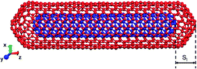
The MD simulations were carried out to understand the feasibility of inner-tube oscillations in CNTs contributing to damping and to estimate the energy dissipation. Previous MD simulation studies used open ended CNTs to simulate inner-tube oscillations.16–18 However, it is observed from the TEM characterization that the CNTs exist with closed ends, like a capped structure. In this study, a CNT model comprising two tubes, a capped (5,5) inner tube and a capped (10,10) outer tube, was used (Fig. 1). The diameter of each tube is determined from the chiral indices (n, m) using the equation , where aC–C = 0.142 nm is the carbon–carbon bond length in the graphene lattice. This set of chiral indices were selected since they result in an inner tube distance, along the radial direction, equal to 3.39 Å. It is close to the realistic value, i.e., 3.4 Å, measured from the TEM images. The spacing between the tubes along the axial direction is termed the axial inner tube distance (Sl). The Sl of the DWCNTs was varied from 2.5 to 10 Å.
The atomic interactions within a tube were described using adaptive inter-molecular reactive bond order (AIREBO) potential.24 This many-body interaction potential can accurately predict the mechanical properties of CNTs as well as the elastic modulus of graphene.25–28 The inter tube interactions in DWCNTs were described using Lennard–Jones (LJ) potential. The parameters used for this potential are σC–C = 3.3407 Å, εC–C = 0.286 KJ mol−1 and a cut off distance rc = 15 Å.29 The system energy is minimized by using the conjugate gradient method. This is then equilibrated at 300 K in a canonical ensemble for 0.1 ns. The time step was 0.01 fs. The inner tube was set to oscillation when the outer tube was displaced along the axis towards the inner tube. Oscillations were performed in a micro-canonical ensemble for 0.8 ns with a time step of 1 fs. The LAMMPS software package was used for all the calculations.30
4. Results and discussion
4.1 Comparison of the damping behaviour of straight and coiled MWCNTs
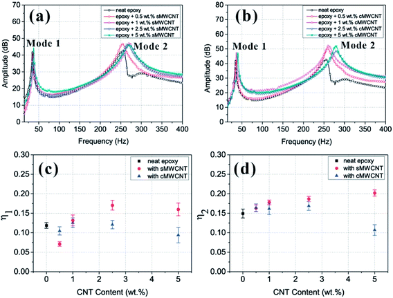
The frequency response functions obtained for nanocomposites reinforced with straight and coiled MWCNTs are given in Fig. 2(a) and (b) respectively. Loss factors in mode 1 (η1) and mode 2 (η2) are calculated by using the procedure given in Section 2.1 and plotted against the CNT content (Fig. 2(c) and (d)). In both the modes, the nanocomposite with sMWCNTs exhibited the highest loss factor; with the increase of the sMWCNT content, the loss factor increases. In the case of cMWCNT reinforced nanocomposites, the loss factor decreases with the increase of the cMWCNT content. In the first mode, the nanocomposites reinforced with 2.5 wt% sMWCNTs exhibited the highest loss factor. It is around 45% higher than that of neat epoxy. In the second mode, the nanocomposites with 5 wt% sMWCNTs exhibited the highest loss factor. It is around 36.5% higher than that of neat epoxy.The incorporation of an optimum content of CNTs increased the vibration damping of nanocomposites compared to that of neat epoxy. The trend in the increase is not identical for the two types of nanocomposites. A strong effect of the structure and morphology of CNTs on vibration damping is also observed. The microstructure of these CNTs needs to be analysed to determine the mechanism of vibration damping.
4.2 Microstructure of CNTs
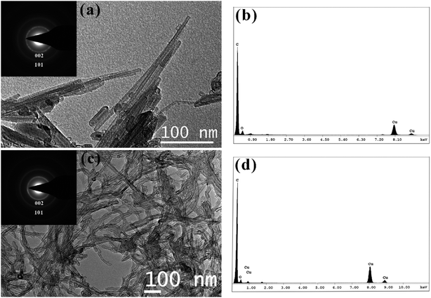
The bright field TEM images of CNTs synthesized by arc discharge and CVD techniques are shown in Fig. 3(a) and (c) respectively. The two varieties of CNTs have distinctly different microstructures. The arc discharge CNTs are straight over the entire length, whereas the CVD CNTs are individually coiled and mutually entangled with many bends and kinks along the length. Selected area electron diffraction (SAED) patterns shown in the inset of Fig. 3(a) and (c) reveal similar reflections for both varieties of CNTs. The pristine nature of their surfaces has been revealed by the energy dispersive X-ray spectra (EDS) of sMWCNTs and cMWCNTs, which are shown in Fig. 3(b) and (d) respectively. The peaks corresponding to copper are from the supporting copper grids and that corresponding to oxygen could be from copper oxide. The diameter of at least 100 CNTs in both the varieties was measured using ImageJ software from the bright field TEM images. The average diameters of sMWCNTs and cMWCNTs are 15.2 ± 5.5 nm and 16.6 ± 6 nm respectively. The average diameters of both varieties of CNTs are very close, within one standard deviation of each other.4.3 Molecular dynamics simulation of inner tube oscillation
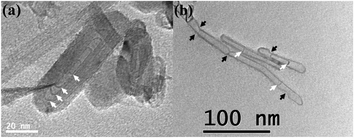
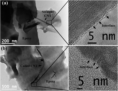
From the free vibration test, a higher loss factor was obtained for nanocomposites with straight CNTs. The difference in the microstructure between the two types of nanocomposites was characterized by TEM. At a particular CNT content, the only difference between the two types of nanocomposites is in the structure and morphology of CNTs. Inner tube oscillation17,18,31,32 is favoured by the structure of sMWCNTs. This is due to the uniform cross section over the entire length of this type of CNT (Fig. 4(a)), whereas the kinks and bends in the cross section of coiled CNTs (Fig. 4(b)) hinder the inner tube oscillation. The sMWCNTs are observed to have more number of inner tubes compared to the cMWCNTs, as visible from the TEM images shown in Fig. 4 (inner tubes are marked using white arrows). Also, the input stress in the free vibration test is around 100 times higher than the shear resistant to inner tube oscillation, which is 0.06 MPa (ref. 14) to 0.08 MPa.13,33The inner tube was set to oscillation when the outer tube was displaced towards the inner tube by a few angstroms which depends on the axial inner tube distance, Sl. In the real case, this displacement was assumed to have resulted from the impact force during the free vibration test. At the epoxy–CNT interface, the synergistic effect of van der Waals forces, mechanical interlocking, thermal mismatch and Poisson's contraction results in high interfacial strength.34 The reported values of interfacial strength are in the range of 70 to 100 MPa.35,36 Hence, the outer tube is coupled to the epoxy matrix through a continuous interface between the matrix and CNTs. The brightfield TEM images of single CNTs of both sMWCNTs and cMWCNTs dispersed in the epoxy matrix are shown in Fig. 5(a) and (b) respectively. High resolution images show the continuous interlocked epoxy–CNT interface. This indicates that, under the application of an external load, the response of the outer tube is coupled with the epoxy matrix. However, the inner tubes show a delayed response because of their inertia. This disturbs the stability of the atomic configuration. As a result, the inner tubes oscillate.
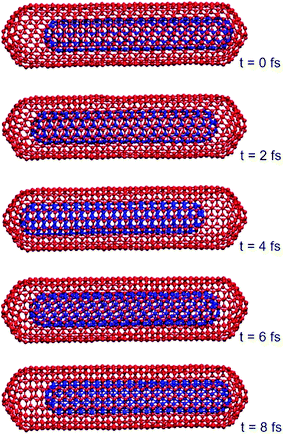
One cycle of such oscillation of the inner tube is shown in Fig. 6. The time period of oscillation is observed to be 8 fs. The potential energy of the inner tube for a time interval of 0.8 ns is shown in Fig. 7.
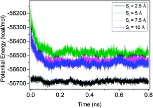 | ||
| Fig. 7 Variation of the potential energy of the inner tube for various axial inner tube distances, Sl = 2.5, 5, 7.5 and 10 Å. | ||
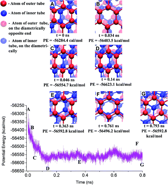
In this, the atoms in the red colour are of the outer tube and in the blue colour are of the inner tube. The atoms in pale red and pale blue are of the outer and inner tubes but at the diametrically opposite end. The inner tube oscillation starts from point A and stops at point E. Three random points were shown in between the starting and ending of the inner tube oscillation. At point B, the atoms of the inner tube are exactly below the atoms of the outer tube, resulting in higher potential energy. Hence, the oscillation continues to minimize the energy. The potential energy at point C is lower than that at point E. However, the oscillation continued from point C. This is due to the momentum of the inner tubes at point C. It is observed that after 0.363 ns, i.e., at point E, there is no considerable axial displacement for the inner tube. Even though the inner tube oscillation progressed through many lower energy states, the oscillation stops only when the momentum of the inner tube cannot overcome the van der Waals interaction between the tubes. The inner tube tries to minimize the energy further by rotation without a significant axial movement. As a result, a lower energy state, which is marked as point G in Fig. 8, is reached.
4.4 Dissipated energy
The energy dissipated by inner tubes is estimated using| ΔE = EFinal − EInitial | (1) |
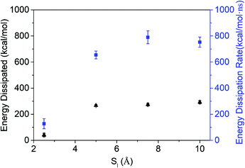 | ||
| Fig. 9 The variation of energy dissipated and the energy dissipation rate in a DWCNT with different axial inner tube distances, Sl, obtained from MD simulations. | ||
The present study explored interface derived damping, a type of energy dissipation mechanism in which the energy dissipation occurs due to the sliding of available interfaces.37 In MWCNTs, there are interfaces within each CNT. These tubes act individually and hence are free to slide inside each other.11 From the loss factor calculated by the free vibration damping test, it is observed that the sMWCNTs are a better reinforcement for damping applications than cMWCNTs. From the MD simulation, significant energy dissipation is observed during the inner tube oscillation in a DWCNT. A proportional increase in the dissipated energy can be expected as the number of inner tubes increases.
5. Conclusions
In this work, epoxy resin reinforced with straight and coiled MWCNTs was prepared and subjected to free vibration tests in order to understand the contributions of the microstructure to the vibration damping behaviour. It is observed that the nanocomposites with straight MWCNTs have a higher loss factor compared to those with coiled MWCNTs in the first and second modes. The loss factor increases with increasing concentration of straight CNTs, whereas it levels off with increasing coiled CNT content. The higher damping observed in the case of composites with straight MWCNTs is attributed to the inner tube oscillations. A higher number of inner tubes are observed in the case of straight MWCNTs and inner tube oscillation is favoured in the case of straight MWCNTs due to the uniform cross section over the entire length. However, in the case of coiled MWCNTs, due to the kinks and bends the free sliding oscillations of the inner tubes are hindered. Molecular dynamics (MD) simulations carried out on DWCNTs are used to explain the energy dissipation originating from the inner tube oscillations. The driving force for the oscillation is the minimization of the interaction potential of the inner tubes. The dissipated energy and the rate of dissipation increased significantly when the axial inner tube distance is increased from Sl = 2.5 Å to 5 Å. However, the energy dissipation rate decreased beyond Sl = 7.5 Å, resulting from the increased time of inner tube oscillation.Conflicts of interest
There are no conflicts to declare.Acknowledgements
The authors gratefully acknowledge the Materials Science Division of the Naval Physical and Oceanographic Laboratory, Cochin, India for the technical discussions and suggestions and the Naval Research Board (NRB) of the Government of India for the financial support.References
- R. Chandra, S. Singh and K. Gupta, Damping studies in fiber-reinforced composites–a review, Compos. Struct., 1999, 46(1), 41–51 CrossRef.
- M. Kireitseu, D. Hui and G. Tomlinson, Advanced shock-resistant and vibration damping of nanoparticle-reinforced composite material, Composites, Part B, 2008, 39, 128–138 CrossRef.
- D. D. L. Chung, Review: Materials for vibration damping, J. Mater. Sci., 2001, 36(24), 5733–5737 CrossRef CAS.
- S. W. Hudnut and D. Chung, Use of submicron diameter carbon filaments for reinforcement between continuous carbon fiber layers in a polymer-matrix composite, Carbon, 1995, 33(11), 1627–1631 CrossRef CAS.
- R. Johnson, J. Tang and R. Pitchumani, Characterization of damping in carbon nanotube filled fiberglass reinforced thermosetting-matrix composites, J. Mater. Sci., 2011, 46(13), 4545–4554 CrossRef CAS.
- J. Wang, C. H. Lee and Y. K. Yap, Recent advancements in boron nitride nanotubes, Nanoscale, 2010, 2(10), 2028–2034 RSC.
- R. Agrawal, A. Nieto, H. Chen, M. Mora and A. Agarwal, Nanoscale damping characteristics of boron nitride nanotubes and carbon nanotubes reinforced polymer composites, ACS Appl. Mater. Interfaces, 2013, 5(22), 12052–12057 CrossRef CAS PubMed.
- H. Rajoria and N. Jalili, Passive vibration damping enhancement using carbon nanotube-epoxy reinforced composites, Compos. Sci. Technol., 2005, 65(14), 2079–2093 CrossRef CAS.
- H. Jiang, M. F. Yu, B. Liu and Y. Huang, Intrinsic energy loss mechanisms in a cantilevered carbon nanotube beam oscillator, Phys. Rev. Lett., 2004, 93(18), 185501 CrossRef CAS PubMed.
- A. Fennimore, T. Yuzvinsky, W. Q. Han, M. Fuhrer, J. Cumings and A. Zettl, Rotational actuators based on carbon nanotubes, Nature, 2003, 424(6947), 408 CrossRef CAS.
- J. Cumings and A. Zettl, Low-friction nanoscale linear bearing realized from multi-wall carbon nanotubes, Science, 2000, 289(5479), 602–604 CrossRef CAS.
- A. N. Kolmogorov and V. H. Crespi, Smoothest bearings: interlayer sliding in multiwalled carbon nanotubes, Phys. Rev. Lett., 2000, 85(22), 4727 CrossRef CAS PubMed.
- Q. Zheng and Q. Jiang, Multiwalled carbon nanotubes as gigahertz oscillators, Phys. Rev. Lett., 2002, 88(4), 045503 CrossRef.
- J. L. Rivera, C. McCabe and P. T. Cummings, Oscillatory behaviour of double-walled nanotubes under extension: a simple nanoscale damped spring, Nano Lett., 2003, 3(8), 1001–1005 CrossRef CAS.
- J. Sumfleth, K. Prehn, M. H. Wichmann, S. Wedekind and K. Schulte, A comparative study of the electrical and mechanical properties of epoxy nanocomposites reinforced by cvd-and arc-grown multi-wall carbon nanotubes, Compos. Sci. Technol., 2010, 70(1), 173–180 CrossRef CAS.
- M. V. Prasad and B. Bhattacharya, Molecular dynamics simulations of carbon nanotube based oscillators having topological defects, Int. J. Nanosci., 2011, 10(01n02), 355–359 CrossRef CAS.
- P. Tangney, S. G. Louie and M. L. Cohen, Dynamic sliding friction between concentric carbon nanotubes, Phys. Rev. Lett., 2004, 93(6), 065503 CrossRef PubMed.
- W. Guo, Y. Guo, H. Gao, Q. Zheng and W. Zhong, Energy dissipation in giga-hertz oscillators from multiwalled carbon nanotubes, Phys. Rev. Lett., 2003, 91(12), 125501 CrossRef PubMed.
- A. J. Berkmans, S. Ramakrishnan, G. Jain and P. Haridoss, Aligning carbon nanotubes, synthesized using the arc discharge technique, during and after synthesis, Carbon, 2013, 55, 185–195 CrossRef.
- A. Joy, S. Varughese, S. Shanmugam and P. Haridoss, Multiwalled carbon nanotube reinforced epoxy nanocomposites for vibration damping, ACS Appl. Nano Mater., 2019, 2, 736–743 CrossRef CAS.
- A. Joy, S. Varughese, S. Shanmugam and P. Haridoss, Role of interface on damping characteristics of multi-walled carbon nanotube reinforced epoxy nanocomposites, Mater. Res. Express, 2019, 1050c4 CrossRef CAS.
- E756-05(2010) A, in Standard test method for measuring vibration-damping properties of materials, ASTM International, West Conshohocken, PA, 2010 Search PubMed.
- D. Ross, E. Ungar and E. Kerwin, Structural damping, ASME, 1959, pp. 49–88 Search PubMed.
- S. J. Stuart, A. B. Tutein and J. A. Harrison, A reactive potential for hydrocarbons with intermolecular interactions, J. Chem. Phys., 2000, 112(14), 6472–6486 CrossRef CAS.
- H. Zhao, K. Min and N. R. Aluru, Size and chirality dependent elastic properties of graphene nanoribbons under uniaxial tension, Nano Lett., 2009, 9(8), 3012–3015 CrossRef CAS PubMed.
- K. Dilrukshi, M. Dewapriya and U. Puswewala, Size dependency and potential field influence on deriving mechanical properties of carbon nanotubes using molecular dynamics, Theor. Appl. Mech. Lett., 2015, 5(4), 167–172 CrossRef.
- V. R. Coluci, S. O. Dantas, A. Jorio and D. S. Galvão, Mechanical properties of carbon nanotube networks by molecular mechanics and impact molecular dynamics calculations, Phys. Rev. B: Condens. Matter Mater. Phys., 2007, 75, 075417 CrossRef.
- J. Zhao, N. Wei, Z. Fan, J. W. Jiang and T. Rabczuk, The mechanical properties of three types of carbon allotropes, Nanotechnology, 2013, 24(9), 095702 CrossRef PubMed.
- A. Kutana and K. Giapis, Transient deformation regime in bending of single-walled carbon nanotubes, Phys. Rev. Lett., 2006, 97(24), 245501 CrossRef CAS PubMed.
- S. Plimpton, Fast parallel algorithms for short-range molecular dynamics, J. Comput. Phys., 1995, 117(1), 1–19 CrossRef CAS.
- S. Legoas, V. Coluci, S. Braga, P. Coura, S. Dantas and D. S. Galvao, Molecular-dynamics simulations of carbon nanotubes as gigahertz oscillators, Phys. Rev. Lett., 2003, 90(5), 055504 CrossRef CAS.
- X. Zhang, G. Santoro, U. Tartaglino and E. Tosatti, Dynamical phenomena in fast sliding nanotube models, Philos. Mag., 2013, 93(8), 922–948 CrossRef CAS.
- M. F. Yu, B. I. Yakobson and R. S. Ruoff, Controlled sliding and pullout of nested shells in individual multiwalled carbon nanotubes, J. Phys. Chem. B, 2000, 104(37), 8764–8767 CrossRef CAS.
- K. K. Ang and K. S. Ahmed, An improved shear-lag model for carbon nanotube reinforced polymer composites, Composites, Part B, 2013, 50, 7–14 CrossRef CAS.
- X. Chen, L. Zhang, M. Zheng, C. Park, X. Wang and C. Ke, Quantitative nanomechanical characterization of the van der waals interfaces between carbon nanotubes and epoxy, Carbon, 2015, 82, 214–228 CrossRef CAS.
- C. A. Cooper, S. R. Cohen, A. H. Barber and H. D. Wagner, Detachment of nanotubes from a polymer matrix, Appl. Phys. Lett., 2002, 81(20), 3873–3875 CrossRef CAS.
- D. Chung, Interface-derived solid-state viscoelasticity exhibited by nanostructured and microstructured materials containing carbons or ceramics, Carbon, 2018, 567–581 Search PubMed.
| This journal is © The Royal Society of Chemistry 2020 |

