 Open Access Article
Mechanically durable and long-term repairable flexible lubricant-infused monomer for enhancing water collection efficiency by manipulating droplet coalescence and sliding†
Hui
Zhou
ab,
Xueshan
Jing
ab and
Zhiguang
Guo
 *ab
*ab
aHubei Collaborative Innovation Centre for Advanced Organic Chemical Materials, Ministry of Education Key Laboratory for the Green Preparation and Application of Functional Materials, Hubei University, Wuhan 430062, People's Republic of China
bState Key Laboratory of Solid Lubrication, Lanzhou Institute of Chemical Physics, Chinese Academy of Sciences, Lanzhou 730000, People's Republic of China. E-mail: zguo@licp.cas.cn; Fax: +86-931-8277088; Tel: +86-931-4968105
First published on 19th February 2020
Abstract
Lubricant-infused surfaces have attracted widespread attention due to their excellent liquid and organic solution repellency. On account of their high condensation heat transfer coefficient and low nucleation energy barrier, many lubricant-infused surfaces have been applied in water collection. However, they have a number of shortcomings, such as an unstable lubricating layer, poor mechanical/chemical stability and hard shedding, which severely limit the application of slippery surfaces. In this work, the silicone oil was infused into a superhydrophobic monomer (SHM) to form a flexible lubricant-infused monomer (FLIM) with outstanding sliding ability and omniphobicity for low surface energy liquids. Because the silicone oil is similar to the base molecule, there is a strong interacting force to hold the lubricant layer to the surface of the SHM. In addition, the high viscosity of the silicone oil further strengthens the lubricant layer adhesion. Therefore, the FLIM could resist hot liquid and high shear stress (up to 5000 rpm). In addition, the FLIM substrate possessed a self-similar low surface energy structure, which could endure various physical and chemical damages, such as abrasion, scratching, stretching, strong acid and alkali. Finally, pinned droplets could coalesce into large droplets to slide down its surface, resulting from the strain/release due to the high degree of deformation of the surface, which highly enhanced water/liquid coalescence and collection. The preparation of the FLIM was green and the chemicals involved were inexpensive and environmentally friendly, and thus it can be applied for large-scale water collection.
1. Introduction
Taking inspiration from lotus leaves,1 rice leaves2 and butterfly wings,3 bioinspired superwettable materials have been introduced into our lives and there have been great advances in their fabrication.4–7 Especially, superhydrophobic materials with a high contact angle and low rolling angle possess great application value in anti-icing,8,9 self-cleaning,10 drag reduction,11 corrosion-resistance12 and oil-water separation.13 However, for their production and extensive utilization in real-world settings, their low environment friendliness and mechanical/chemical stability urgently need to be solved.7 Although fluorinated substances and volatile organic compounds can reduce the surface energy of surfaces, they have been identified as a source of toxic pollutants, and thus their use is restricted.14 Recently, it has been reported that some superhydrophobic materials were fabricated using nonfluorinated or waterborne materials.15–17 However, they suffer from chemical and mechanical damage in various environments, such as strong acid and alkali, high temperature, UV irradiation, scratching, touching and abrasion, and thus easily lose their superhydrophobicity.18 Therefore, new superhydrophobic materials need to be prepared to resist various damages. For example, an ultra-robust superhydrophobic fabric with mechanical stability, UV durability, and UV shielding property was prepared successfully.19 Therefore, other new superhydrophobic materials still need to be fabricated to resist various damages.Recently, many researchers infused lubricants into porous substrates with nano-topography and low surface energy to form stable and inert slippery interfaces, inspired by the Nepenthes pitcher plant.20–22 In addition, Zhu et al. prepared a lubricant-impregnated coating with long-term stable slipperiness and self-replenishment properties via a simple method.23 Due to the existence of a lubricating liquid, slippery surfaces have the ability to realize omniphobicity and low sliding angles. However, the problems of poor locking lubricant, chemical instability and fragile structure severely limit the development of slippery surfaces. Accordingly, many articles have been reported to improve the stability of the lubricant layer.24–26 Nevertheless, the substrate structure was easily destroyed by scratching, compression and abrasion, and thus the slippery surfaces lost their sliding and lubricant locking ability.
Collecting fog by employing different strategies is an important way to solve the water shortage problem in arid regions. Accordingly, numerous biomimetic fog-harvesting materials, superhydrophobic surfaces27,28 and hydrophobic/hydrophilic surfaces,29,30 have been studied and fabricated to collect water based on inspiration from the Namib Desert beetle,31 spider silk32 and cactus.33 The collection of water is usually divided into three parts, including water capture, water supply and water removal.34,35 Water capture is the process of capturing tiny droplets on the surface of harvesting materials. Water supply is the process of coalescence between droplets in a fog episode and water droplets. Water removal (drainage) is the process of drainage of harvested water. Under the action of gravity, the gradually growing droplets slide down from the surface. However, compared to superhydrophobic surfaces and hydrophobic/hydrophilic surfaces, FLIM surfaces have better water collection capacity due to their excellent heat transfer efficiency and low nucleation energy, which has been proved in previous reports.36,37 Because the thickness of the infused lubricant decreases with time, the rough base layer is exposed and the water sliding ability cannot exist for a long period. In addition, on a rigid substrate, the droplets are easily blown away by natural wind. Also, the pinned water droplets on water-harvesting surfaces limit the nucleation of new droplets, thus hindering the water collection. Thus, it is important to speed up the growth of droplets or bring together tiny droplets to slide down quickly.
Recently, bulk materials with a self-similar structure, foams, sponge, and layer-by-layer coatings have attracted much attention due to their excellent mechanical properties.7 Herein, silicone oil was infused into an SHM to form a super-durable FLIM with a sliding angle of less than 5° and omniphobicity. The lubricant in this work was silicone oil (PDMS), which was similar to the bulk substrate prepared using PDMS. Therefore, the lubricant could be locked in the SHM firmly. Due to the mechanical and chemical durability of the monomer material, the FLIM exhibited outstanding ability to resist hot water, scratching, strong acid/alkali and high shear stress. To determine the most suitable lubricant thickness for water collection, the lubricant layer thickness was calculated based on the change in lubricant quality, and a water collection experiment was carried out. Under the action of external force, the FLIM could control the sliding of the droplet by compressing and stretching. Hence, the pinned droplets could coalesce into large droplets to slide down the surface according to strain/release due to the high degree of deformation of the surface, which highly enhanced the water/liquid coalescence and collection. The FLIM greatly improved the life of the slippery material and improved the water collection efficiency under various extreme conditions.
2. Experimental
2.1 Materials
Polydimethylsiloxane (PDMS) silicone elastomer precursor (Sylgard 184A) and the curing agent (Sylgard 184B) were obtained from Dow Corning Corporation. SiO2 nanoparticles were purchased from Meryer Chemical Technology Co., LTD. Trimethylsiloxy-terminated PDMS (silicone oil) was purchased from Shanghai Macklin Biochemical Technology Co., Ltd.2.2 Preparation of the slippery silicon monomer
![[thin space (1/6-em)]](https://www.rsc.org/images/entities/char_2009.gif) :
:![[thin space (1/6-em)]](https://www.rsc.org/images/entities/char_2009.gif) 1 in a 50 mL beaker, and then stirred at 1000 rpm. Next, SiO2 nanoparticles were dispersed in water at a ratio of 1
1 in a 50 mL beaker, and then stirred at 1000 rpm. Next, SiO2 nanoparticles were dispersed in water at a ratio of 1![[thin space (1/6-em)]](https://www.rsc.org/images/entities/char_2009.gif) :
:![[thin space (1/6-em)]](https://www.rsc.org/images/entities/char_2009.gif) 10. Then, the dispersed solution (solution A) of water and SiO2 nanoparticles was added to the uncured PDMS dropwise at a rate of 50 mL h−1 under stirring using a magnetic stirring apparatus at a speed of 1000 rpm. Herein, the mass ratio of Sylgard 184
10. Then, the dispersed solution (solution A) of water and SiO2 nanoparticles was added to the uncured PDMS dropwise at a rate of 50 mL h−1 under stirring using a magnetic stirring apparatus at a speed of 1000 rpm. Herein, the mass ratio of Sylgard 184![[thin space (1/6-em)]](https://www.rsc.org/images/entities/char_2009.gif) :
:![[thin space (1/6-em)]](https://www.rsc.org/images/entities/char_2009.gif) water
water![[thin space (1/6-em)]](https://www.rsc.org/images/entities/char_2009.gif) :
:![[thin space (1/6-em)]](https://www.rsc.org/images/entities/char_2009.gif) SiO2 was 20
SiO2 was 20![[thin space (1/6-em)]](https://www.rsc.org/images/entities/char_2009.gif) :
:![[thin space (1/6-em)]](https://www.rsc.org/images/entities/char_2009.gif) 10
10![[thin space (1/6-em)]](https://www.rsc.org/images/entities/char_2009.gif) :
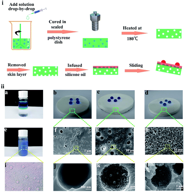
:![[thin space (1/6-em)]](https://www.rsc.org/images/entities/char_2009.gif) 1. Upon the addition of the nanoparticle dispersion solution gradually, a white and creamy emulsion was formed. After stirring for 1 h, the emulsion was poured into a polystyrene Petri dish and placed under vacuum to degas for 3 h, which was vital for the discharge of gas. To cure PDMS and prevent water in the emulsion from evaporation, the polystyrene Petri dish was sealed and placed in an oven at 70 °C for 3 h. Finally, the prepared silicon monomer was placed in an oven at 180 °C for 2 h, and the water evaporated to form a micro/nano-structure during heating. Therefore, the SHM was prepared. The whole preparation process is shown in Fig. 1i.
1. Upon the addition of the nanoparticle dispersion solution gradually, a white and creamy emulsion was formed. After stirring for 1 h, the emulsion was poured into a polystyrene Petri dish and placed under vacuum to degas for 3 h, which was vital for the discharge of gas. To cure PDMS and prevent water in the emulsion from evaporation, the polystyrene Petri dish was sealed and placed in an oven at 70 °C for 3 h. Finally, the prepared silicon monomer was placed in an oven at 180 °C for 2 h, and the water evaporated to form a micro/nano-structure during heating. Therefore, the SHM was prepared. The whole preparation process is shown in Fig. 1i.
2.3 Stability tests for SHM and FLIM
The stability of the SHM was tested under many conditions, such as finger touching, scratching, folding, high compression of 10 MPa and tape peeling. The friction test was carried out under a pressure of 1 kg using 400 mesh sandpaper. The compression and tensile properties were tested using an electronic universal testing machine. The sliding speeds of water droplets under different temperatures on the FLIM (5° tilt angle) were measured. After the FLIM was rubbed repeatedly, its surface was refilled, and the sliding performance was tested again. The experimental results showed that the sliding property remained unchanged after repeated friction.To explore the locking lubricant ability, the FLIM was placed under various spin rates and then its sliding performance was tested again.
2.4 Water collection measurements
In our work, the prepared samples with dimensions of 3 × 2.3 × 0.3 cm3 were fixed in a self-made testing system to evaluate the fog-harvesting performance. The purpose-built fog collection test system consisted of a commercial humidifier (tank with a capacity of 1.6 L and fog output of 200 mL h−1) and a large glass container with the humidifier. The as-prepared samples with different surface wettabilities fixed on a holder were perpendicular to the horizontal plane in front of the fog outlet so that the water droplets collected by the surface could roll down on account of gravity. Herein, to avoid the influence of air flow on the fog and external wind, the sample was placed in a glass container. Then, the FLIM was placed on the bracket in front of the mist outlet and perpendicular to the horizontal plane. The collected water droplets were removed from the surface under gravity.The distance between the samples and fog outlet was 5 cm, and the distance between the fog outlet and collection container was 15 cm. Placing the same fog collection container as a control group was necessary, which was beneficial to eliminate the influence of external fog. The duration of one cycle measurement was 1 h and all experimental data were averaged after five measurements. The flow rate and speed of this commercial humidifier were 0.0556 g s−1 and about 25 cm s−1, respectively. During the experiment, the temperature and relative humidity around the samples were 18 °C and 70%, respectively. The weight of the collected water was measured with an electronic balance. The efficiency of fog collection and droplet circulation was calculated using the relationship η = m/t, where m is the mass of the collected water after 1 h, and t is the time of the fog collection process.
2.5 Characterization
The microstructure and morphology of the samples were observed via field-emission scanning electron microscopy (FESEM, JSM-6701F). The static water contact angle (SCA) of the specimens was measured using a JC2000D system with a 5 μL droplet. The surface compositions of the ZnO samples were analyzed via energy dispersive spectroscopy (EDS) attached to a scanning electron microscope (SEM, JEOL JSM-5600LV). Their quantitative elemental composition was characterized via X-ray photoelectron spectroscopy (XPS, Thermo Scientific ESCALAB 250Xi). Compression and tensile properties were tested using an electronic universal testing machine (EZ Test EZ-LX).3. Results and discussion
3.1 The preparation of flexible liquid infused monomer
To prepare the liquid-infused monomer, the preparation of an SHM was necessary. Due to its low surface energy (γSV = 20 mJ m−2), PDMS was modified to prepare the superhydrophobic substrate.38 During the preparation process, water was added to PDMS dropwise to form a uniform emulsion under the conditions of no surfactant or electrolyte, as shown in Fig. 1ii(a and e). With the constant addition of water droplets, the emulsion became thicker and the phase separation of the oil–water occurred. As shown in Fig. 1ii(i), water droplets with a similar diameter were dispersed in the uncured PDMS. After curing at 180 °C, the water phase formed different morphologies in the uncured PDMS, which existed throughout the whole bulk material. As shown in Fig. S1b,† the microscopic pores filled the entire monomer. As displayed in Fig. 1ii(f and g), the diameter of the cavity showed a big difference, resulting from the droplet coalescence since the emulsions were heated to initiate curing.To improve the superhydrophobicity of the monomer, a large amount of SiO2 nanoparticles was dissolved in water and added to PDMS. Therefore, the bulk mater material was full of micro-nanostructures after heating at 180 °C. The SiO2 nanoparticles were tightly attached to the wall of every hole (see Fig. 1ii(g and k)). The contact angle on the SHM was 156° and the roll angle was 5° (see the Fig. 1ii(c)). However, initially, the hydrophobicity of the SHM was blocked by the “skin” that hid the hydrophobic structure, which had a contact angle of 127° and the water droplets were pinned in the surface. Hence, the hydrophobicity of the SHM was poor, as shown in Fig. 1ii(d, h, l) and S1a.† When only water was added, the inner wall of the hole was smooth and the hydrophobicity was poor, and the contact angle was only 120° and water droplets were pinned on the surface (see Fig. 1ii(b, f, j) and S1a†).
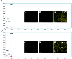
To obtain the micro-nanostructure, SiO2 nanoparticles were dispersed in the water/PDMS emulsion. After curing and heating, the SiO2 nanoparticles were attached to the wall of every hole. As shown in Fig. 2a and b, the prepared sample only has three elements of C, Si, O. Also, the Si content of the SHM increased from 9.15% to 28.93% compared to the sample without the silica particles, which proved that the SiO2 nanoparticles were embedded in the SHM. After removing the skin of the SHM, silicone oil was injected onto the surface of the sample to form a uniform oil film under high-speed centrifugation. The reason why silicone oil was chosen is that its molecule is similar to the substrate molecule and it has high viscosity, which are beneficial for its attachment to the surface to form a uniform lubricant layer. In addition, silicone oil possesses a low surface tension (less than 25 mN m−1) and has superior stabilities against thermal, chemical, and photo-catalytic degradation.39,40 Accordingly, the flexible slippery monomer was successfully prepared.
3.2 The mechanical abilities of the superhydrophobic monomer
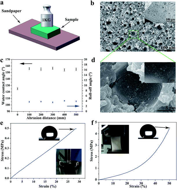
By reason of the self-similar structure and flexibility of silicone, the SHM had superior ability to resist abrasion, compression, stretching, and touching. After destruction by mechanical damage, although the surface structure was destroyed, the new superhydrophobic structure reappeared and the hydrophobicity did not change. This is because the low-surface-energy microstructures are extended to the whole volume. As shown in Fig. 3a, the sample was rubbed multiple times on sandpaper under a pressure of 1 kg. Initially, the skin of the original sample exhibited poor hydrophobicity. With an increase in the abrasion distance, no significant changes in contact angle and roll angle were observed at 156° and 5°, respectively (see Fig. 3c). Herein, we only measured the length of 500 mm for the friction. However, the SHM could resist longer friction lengths if the sample is not depleted.This is because the low surface energy microstructures were extended to the whole monomer. As displayed in Fig. 3b and d, the SHM had a new structure exposed after abrasion for 100 mm and the SiO2 nanoparticles were still attached to the inner wall of the holes. Furthermore, the SHM could resist other mechanical damage such as finger touching, high compression for 10 MPa, tape peeling and bending, as shown in Fig. S2.† After heating at 250 °C, the SHM still maintained outstanding superhydrophobicity.
Moreover, the SHM possessed superior tensile and compression resistance by reason of the flexibility of the silicone, which dispersed energy upon the deformation of the elastic material. The superhydrophobic flexible monomer had outstanding tensile and compressive properties. As shown in Fig. 3e and f, the stretching and compressing strength of the SHM was investigated by performing tensile and compression tests.
Samples with a size of 10 × 10 mm2 and 40 × 20 mm2 were subjected to tensile and compress tests under the action of external force at a speed of 10 mm min−1. As displayed in Fig. 3e, the compression strength and strain were about 0.5 MPa and 30%, respectively (the external force here could only reach 500 N). After the external force was unloaded, the sample returned to its original shape without hydrophobicity change. Furthermore, the stress strength and strain were about 4.5 MPa and 50% (see Fig. 3f). Although the sample broke, the sample had good elasticity, and the hydrophobicity and microscopic morphology did not change. The reason why the SHM had excellent mechanical properties was because the SiO2 nanoparticles were fixed throughout the sample and exhibited strong interfacial interactions with PDMS. Also, the silicone could resist external damage by dispersing energy upon the deformation of the elastic material. Therefore, the SHM had superior mechanical properties to endure various damage.
3.3 Sliding ability and stability of flexible lubricant-infused monomer
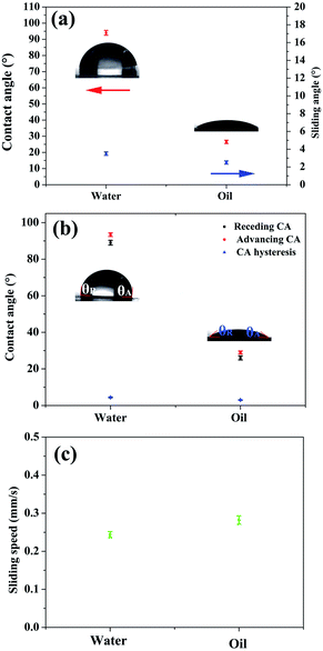
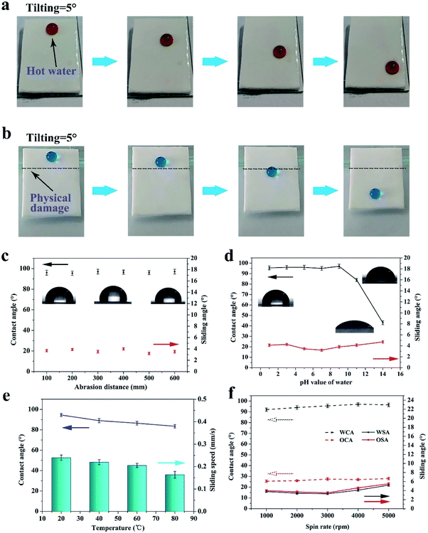
After the skin of the SHM was removed, silicone oil was infused to form a uniform lubricant layer under high speed centrifugation. Due to the high viscosity and intermolecular attraction, the lubricant existed stably in the micropores, and thus could resist various harsh working conditions, such as hot water, scratching, high shear stress and compression. The surface of FLIM retained its omniphobicity for water and oleic oil. The contact angles of water and oleic oil were 96° and 26°, respectively. Also, on the surface of the FLIM, the water droplet and oleic oil could slide from it easily with sliding angles of 3.4° and 2.6°, respectively (see Fig. 4a). The sliding angle of water was larger than oleic oil because the contact angle (CA) hysteresis of water was larger than oleic oil. As shown in Fig. 4b, the CA hysteresis of water is 2.9°, while that of oleic oil is 2.3°. Upon dropping 10 μL water and oleic oil on a 5° tilted surface, the sliding speed of water was 0.244 mm s−1 and water was 0.282 mm s−1 (see Fig. 4c).To explore the stability of the FLIM, its characteristics of resisting hot water, physical damage and high shear stress were measured. The silicone oil was locked in the SHM to form a stable lubricant layer because the intermolecular attraction of the silicone oil molecular was similar to that of the PDMS substrate. Also, its flexible self-similar structure could resist various physical damage by releasing energy after deformation.
For the mechanical stability, as shown in Fig. 5b, despite the scratch on the FLIM, water droplets could still slide down from the 5° tilted surface. This is because the silicone oil had fluidity that can be filled into the scratch, reforming a uniform continuous oil layer.
Furthermore, the FLIM could endure abrasion. Although the slide angle of the sample increased sharply after abrasion for 10 mm and the lubricant layer was reduced by 62.1% and the sliding angle of water increased to 14.5°, the slide angle returned to the original value after refilling. After abrasion several times, the large loss in lubrication caused the oil layer to disappear. However, a new similar structure was exposed after the friction (see Fig. 3b), and the new oil layer was restored to the original sliding angle and contact angle after refilling, as shown in Fig. 5c.
To explore the stability of the lubricant layer, the sample was placed on a centrifuge to undergo different shear stress. As shown in Fig. 5f, the water and oleic acid contact angle had a tendency to increase with an increase in the spin rate.
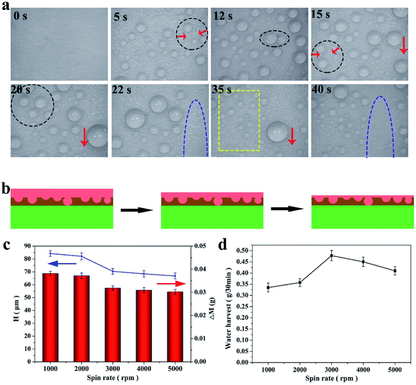
Since the thickness of the lubricant layer was thinning, the contact angle of water and oleic acid became 96° and 27°, respectively. Moreover, the sliding angle of water and oleic acid increased first and then decreased. This is because initially, the lubricant layer was too thick to prevent the movement of the droplets, while the lubricant layer was too thin and the exposure of the rough substrate prevented the movement of the droplets. As displayed in Fig. 6b, the lubricant layer thinned with an increase in the spin rate. However, the thickness of the lubricant layer was still about 55 μm at 5000 rpm, which exhibited that the FLIM has excellent ability to lock the lubricant.
In addition, the FLIM had superior ability to resist hot water and strong acid and alkali solution. The image of hot water sliding on the 5° tilt surface of the FLIM is shown in Fig. 5a. As the water temperature increased, the contact angle decreased from 94° to 83.5° because the surface tension of water decreases with an increase in temperature (see Fig. 5e).9 Also, the sliding speed of the hot water decreased with an increase in temperature since the condensed vapor of hot water on the lubricant layer hindered the movement of the water droplets.20 However, the speed was not significantly reduced, which was 0.164 mm s−1 at 80 °C compared to 0.24 mm s−1 at 20 °C. The sliding state is shown in Fig. 5a. Furthermore, the FLIM exhibited outstanding ability to endure strong acid and alkali. The contact angle of water does not change under strong acid conditions. In contrast, under strong alkali conditions, the contact angle on the FLIM changed from 96.5° to 43° (see Fig. 5d). However, the sliding angle was still less than 4°. Therefore, the FLIM had outstanding chemical and mechanical stability to endure a variety of extreme conditions, which greatly expands its range of applications.
3.4 The flexible lubricant-infused monomer for water collection
Fog, which is an important water source in arid regions, is an effective way to solve water issues. Therefore, fog harvesting is a potential way to obtain freshwater in arid areas. Herein, a stable FLIM, exhibiting omniphobicity for many liquids, was fabricated to harvest water in various harsh working conditions. Usually, water collection is divided into three parts, water capture (condensation), water supply and water removal, which are mainly described in following part. For water capture, many droplets condensed on the FLIM, and the water droplets increased with increase of time (see Fig. 6a). The reason why the FLIM was chosen to collect water was that its nucleation energy barrier is lower for infused surfaces compered to superhydrophobic surfaces, which is beneficial to collect fog. In addition, with time, the water droplets grew gradually, as shown in Fig. 6a for 5 s and 12 s. The micro-nano structures could capture more droplets and accelerate the growth rate of droplets on them.41–43 Also, the lubricant layer has a superior heat transfer performance, which promoted the growth of the condensed droplets. As the fog continued to be captured, many droplets accumulated into larger droplets slowly. As shown in Fig. 6a by the black circles and red down arrow, the small droplets collected into larger droplets, and slid away under the force of gravity.Since the infused silicone oil replaced the air layer in the micro/nanostructures, the droplets easily grew and moved due to the higher thermal conductivity of the lubricant than gas and negligible CA hysteresis. The droplets moved continuously at high speed and removed other droplets, paving the way for the nucleation of new droplets. As displayed in the yellow box in Fig. 6a, the FLIM continued to capture fog and form new droplets in the blank area. Therefore, the FLIM could collect more water continuously.
It is worth noting that the thickness of the infused silicone oil had an important effect on the water collection. Herein, the thickness of the lubricant was controlled by the spin rate and calculated based on the changes in the quality of the lubricant layer. The thickness, H (μm), can be calculated according to the following formula:
 | (1) |
When the spin rate increased, the quality of the lubricant layer decreased from 0.0468 g to 0.0371 g and its thickness decreased from 68.7 μm to 54.46 μm (see Fig. 6c). The amount of water collected varied with the thickness of the lubricant layer, as displayed in Fig. 6d. At the 3000 rpm (the thickness of the lubricant layer was 57.4 μm), the FLIM collected the most water with 0.478 g/30 min. At 1000 rpm, the thickness of the lubricating layer was thicker to form droplets with significant wrapping layers, and thus non-agglomerated droplets were formed. When the oil layer was too thin, the droplet mobility became slow and the nucleation efficiency became worse, thus the quality of water collection was 0.4103 g/30 min at 5000 rpm. Hence, a reasonable thickness of the lubricant layer is beneficial to collect water.
3.5 Enhancing water collection by the relaxation of the imposed strain
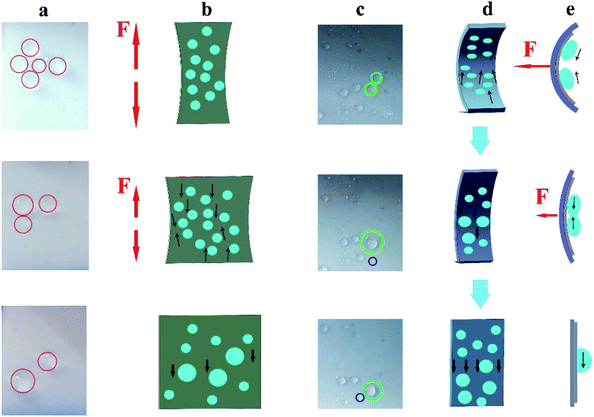
In the relaxed state, droplets could slide freely on the FLIM. However, when tension was applied, the sample was deformed and changed from a flat surface into a rough and porous surface. The deformation induced by stretching reduced the pressure in the porous matrix and caused the lubricant to retreat into the pores.44 Therefore, even at large sliding angles, the sliding of the droplets on the stretched surface slowed down or even stopped. As shown in the first image in Fig. 7a, the droplet did not slide on the surface of the vertical stretch relative to the sliding angle of 3.4° in the relaxed state. In the previous section, we explored the tensile property of the FLIM, which could be stretched by about 50% (see Fig. 3f). Hence, the sliding state could be controlled by deforming the surface by applying an external force. When the pulling force was gradually reduced, the distance between fixed droplets was also reduced, causing them to aggregate into large droplets until the sliding threshold value was exceeded, and then removed from the FLIM. The sliding large droplets slid down together with the small droplets nearby. As displayed in Fig. 7b, as the tensile stress decreased, the small water droplets coalesced along the reverting direction until they started sliding. Similarly, when an external force was applied, the FLIM was compressed and changed into the relaxed state (see Fig. 7d). The attached droplets coalesced in the direction of relaxation, and their size increased sharply, causing them to fall off. As shown in the green circle in Fig. 7c, the droplets moved in the direction of relaxation and pooled together to become large droplets. When the external force was released, the large droplets slid down against the resistance. By stretching and compressing the surface to be greatly deformed, a large number of adjacent tiny droplets could be brought together to become large droplets, which could be quickly removed on the surface, and this is beneficial to collect water. Thus, the movement of the droplet could be manipulated artificially.Due to its remarkably high deformation ability, the FLIM has potential to collect more water compared to undeformed surfaces. Herein, we explored the impact of different compression times (2 min per cycle, 4 min per cycle, and 6 min per cycle) on water collection. The compressed process is shown in Fig. 7d. After the measurement, more water could be collected every 2 min to reach 0.3092 g/30 min. Also, although only 0.278 g was collected at 4 min per cycle, this was slightly higher than the uncompressed FLIM, as shown in Fig. S3.† This is because in about 2 min or 6 min, many small adhered droplets formed on the slippery surface. As the force compressed, the small droplets converged into larger droplets and slid off the surface (see Fig. 7e, where the adjacent droplets were brought together into a large droplet and slid down). While in about 4 min, many large droplets slipped off, with only a small number of small droplets attached to the surface. Therefore, more water could be collected by compressing the FLIM. Furthermore, the thickness of the lubricant layer did not change after multiple compressions.
4. Conclusion
Recently, lubricant-infused surfaces have attracted increasing attention due to their omniphobicity and outstanding sliding ability.24,25 However, there are many shortcomings in the traditional lubricant infused materials that limit their development, such as poor locking lubricant ability and hot liquid repellency, and fragile structure.9,45 PDMS with a low surface tension is used as a hydrophobic material due to its superior stability against thermal, chemical, and photo-catalytic degradation.46,47 Herein, silicone oil was infused into an SHM to form a durable FLIM with a sliding angle of less than 4° and omniphobicity for low surface energy liquids. Herein, the lubricant was trimethylsiloxy-terminated PDMS, which is similar to the substrate prepared using PDMS. Hence, strong interactions existed between the silicone oil molecules and substrate molecules. Also, the silicone oil possessed high viscosity. Thus, the lubricant layer could be locked in the surface firmly. Due to the durable bulk substrate and stable lubricant layer, the FLIM exhibited outstanding ability to resist hot water, scratching, strong acid/alkali and high shear stress. Furthermore, the oil layer thickness was calculated based on the change in lubricant quality, and thus a reasonable lubricant thickness should be applied for water collection. Under the action of external force, the deformation of the FLIM induced by stretching reduced the pressure in the porous matrix and caused the lubricant to retreat into the pores. Therefore, the FLIM could control the sliding of the droplet by compressing and stretching. In addition, according to the high degree of deformation of the surface resulting from the strain/release, the pinned droplets could coalesce into large droplets to slide down the surface. Therefore, the water/liquid coalescence and collection were highly improved and enhanced. Accordingly, the durable FLIM has great potential applications in water collection since it can withstand extreme severe working conditions.Conflicts of interest
There are no conflicts to declare.Acknowledgements
This work is supported by the National Natural Science Foundation of China (No. 51675513 and 51735013)Notes and references
- Y. M. Zheng, X. F. Gao and L. Jiang, Soft Matter, 2007, 3, 178–182 RSC.
- L. Feng, S. H. Li, Y. S. Li, H. J. Li, L. J. Zhang, J. Zhai, Y. L. Song, B. Q. Liu, L. Jiang and D. B. Zhu, Adv. Mater., 2002, 14, 1857–1860 CrossRef CAS.
- W. Barthlott and C. Neinhuis, Planta, 1997, 202, 1–8 CrossRef CAS.
- Y. H. Sung, Y. D. Kim, H. J. Choi, R. Shin, S. Kang and H. Lee, Appl. Surf. Sci., 2015, 349, 169–173 CrossRef CAS.
- F. Xiao, S. J. Yuan, B. Liang, G. Q. Li, S. O. Pehkonen and T. J. Zhang, J. Mater. Chem. A, 2015, 3, 4374–4388 RSC.
- W. Jiang, J. He, M. Mao, S. J. Yuan, H. F. Lu and B. Liang, Ind. Eng. Chem. Res., 2016, 55, 5545–5555 CrossRef CAS.
- X. S. Jing and Z. G. Guo, J. Mater. Chem. A, 2018, 6, 16731–16768 RSC.
- D. Mangini, C. Antonini, M. Marengo and A. Amirfazli, Cold Reg. Sci. Technol., 2015, 109, 53–60 CrossRef.
- X. S. Jing and Z. G. Guo, Nanoscale, 2019, 11, 8870–8881 RSC.
- S. S. Latthe, P. Sudhagar, A. Devadoss, M. Kumar, S. H. Liu, C. Terashima, K. Nakata and A. Fujishima, J. Mater. Chem. A, 2015, 3, 14263–14271 RSC.
- J. Yong, F. Chen, Q. Yang, J. Huo and X. Hou, Chem. Soc. Rev., 2017, 46, 4168–4217 RSC.
- N. Wang, D. Xiong, Y. Deng, Y. Shi and K. Wang, ACS Appl. Mater. Interfaces, 2015, 7, 6260–6272 CrossRef CAS PubMed.
- X. T. Zhu, Z. Z. Zhang, Y. M. Song, J. Y. Yan, Y. Y. Wang and G. N. Ren, J. Taiwan Inst. Chem. Eng., 2017, 71, 421–425 CrossRef CAS.
- M. H. Russell, W. R. Berti, B. Szostek and R. C. Buck, Environ. Sci. Technol., 2008, 42, 800–807 CrossRef CAS PubMed.
- H. Ye, L. Zhu, W. Li, H. Liu and H. Chen, J. Mater. Chem. A, 2017, 5, 9882–9890 RSC.
- A. Milionis, K. Dang, M. Prato, E. Loth and I. S. Bayer, J. Mater. Chem. A, 2015, 3, 12880–12889 RSC.
- G. N. Ren, Y. M. Song, X. M. Li, Y. L. Zhou, Z. Z. Zhang and X. T. Zhu, Appl. Surf. Sci., 2018, 428, 520–525 CrossRef CAS.
- C. H. Xue and J. Z. Ma, J. Mater. Chem. A, 2013, 1, 4146–4161 RSC.
- G. N. Ren, Y. M. Song, X. M. Li, B. Wang, Y. L. Zhou, Y. Y. Wang, B. Ge and X. T. Zhu, J. Colloid Interface Sci., 2018, 522, 57–62 CrossRef CAS PubMed.
- U. Manna and D. M. Lynn, Adv. Mater., 2015, 27, 3007–3012 CrossRef CAS PubMed.
- U. Manna, N. Raman, M. A. Welsh, Y. M. Zayas-Gonzalez, H. E. Blackwell, S. P. Palecek and D. M. Lynn, Adv. Funct. Mater., 2016, 26, 3599–3611 CrossRef CAS.
- H. F. Bohn and W. Federle, Proc. Natl. Acad. Sci. U. S. A., 2004, 101, 14138–14143 CrossRef CAS PubMed.
- X. T. Zhu, J. W. Lu, X. M. Li, B. Wang, Y. M. Song, X. Miao, Z. J. Wang and G. N. Ren, Ind. Eng. Chem. Res., 2019, 58, 8148–8153 CrossRef CAS.
- R. Togasawa, F. Ohnuki and S. Shiratori, ACS Appl. Nano Mater., 2018, 1, 1758–1765 CrossRef CAS.
- M. Tenjimbayashi, J. Y. Park, J. Muto, Y. Kobayashi, R. Yoshikawa, Y. Monnai and S. Shiratori, ACS Biomater. Sci. Eng., 2018, 4, 1871–1879 CAS.
- S. Wooh and H. J. Butt, Angew. Chem., Int. Ed., 2017, 56, 4965–4969 CrossRef CAS PubMed.
- C. Dorrer and J. Rühe, Langmuir, 2008, 24, 6154–6158 CrossRef CAS.
- L. Zhang, J. Wu, M. N. Hedhili, X. Yang and P. Wang, J. Mater. Chem. A, 2015, 3, 2844–2852 RSC.
- Z. W. Yu, F. F. Yun, Y. Q. Wang, L. Yao, S. X. Dou, K. S. Liu, L. Jiang and X. L. Wang, Small, 2017, 13, 1701403 CrossRef PubMed.
- L. S. Zhong, J. Feng and Z. G. Guo, J. Mater. Chem. A, 2019, 7, 8405–8413 RSC.
- R. Parker and C. R. Lawrence, Nature, 2001, 414, 33 CrossRef PubMed.
- Y. Zheng, H. Bai, Z. Huang, X. Tian, F.-Q. Nie, Y. Zhao, J. Zhai and L. Jiang, Nature, 2010, 463, 640 CrossRef CAS PubMed.
- J. Ju, H. Bai, Y. Zheng, T. Zhao, R. Fang and L. Jiang, Nat. Commun., 2012, 3, 1247 CrossRef PubMed.
- B. White, A. Sarkar and A. M. Kietzig, Appl. Surf. Sci., 2013, 284, 826–836 CrossRef CAS.
- K. C. Park, P. Kim, A. Grinthal, N. He, D. Fox, J. C. Weaver and J. Aizenberg, Nature, 2016, 531, 78 CrossRef CAS PubMed.
- S. Anand, A. T. Paxson, R. Dhiman, J. D. Smith and K. K. Varanasi, ACS Nano, 2012, 6, 10122–10129 CrossRef CAS PubMed.
- H. Tsuchiya, M. Tenjimbayashi, T. Moriya, R. Yoshikawa, K. Sasaki, R. Togasawa, T. Yamazaki, K. Manabe and S. Shiratori, Langmuir, 2017, 33, 8950–8960 CrossRef CAS PubMed.
- A. Davis, S. Surdo, G. Caputo, I. S. Bayer and A. Athanassiou, ACS Appl. Mater. Interfaces, 2018, 10, 2907–2917 CrossRef CAS PubMed.
- Z. Y. Deng, W. Wang, L. H. Mao, C. F. Wang and S. V. Chen, J. Mater. Chem. A, 2014, 2, 4178–4184 RSC.
- Q. F. Xu, Y. Liu, F. J. Lin, B. Mondal and A. M. Lyons, ACS Appl. Mater. Interfaces, 2013, 5, 8915–8924 CrossRef CAS PubMed.
- Y. Lu, L. Yu, Z. Zhang, S. Wu, G. Li, P. Wu, Y. Hu, J. Li, J. Chub and D. Wu, RSC Adv., 2017, 7, 11170–11179 RSC.
- H. G. Andrews, E. A. Eccles, W. C. Schofield and J. P. Badyal, Langmuir, 2011, 27, 3798–3802 CrossRef CAS.
- L. S. Zhong, H. Zhu, Y. Wu and Z. G. Guo, J. Colloid Interface Sci., 2018, 525, 234–242 CrossRef CAS.
- X. Yao, Y. H. Hu, A. Grinthal, T. S. Wong, L. Mahadevan and J. Aizenberg, Nat. Mater., 2013, 12, 529–534 CrossRef CAS PubMed.
- Q. Li and Z. G. Guo, J. Colloid Interface Sci., 2019, 536, 507–515 CrossRef CAS.
- Z. Y. Deng, W. Wang, L. H. Mao, C. F. Wang and S. Chen, J. Mater. Chem. A, 2014, 2, 4178–4184 RSC.
- S. Wooh, N. Encinas, D. Vollmer and H.-J. Butt, Adv. Mater., 2017, 29, 1604637 CrossRef PubMed.
Footnote |
| † Electronic supplementary information (ESI) available. See DOI: 10.1039/d0na00003e |
| This journal is © The Royal Society of Chemistry 2020 |

