 Open Access Article
Perpendicularly aligned nanodomains on versatile substrates via rapid thermal annealing assisted by liquid crystalline ordering in block copolymer films†
Ting
Qu
,
Song
Guan
,
Xiaoxiong
Zheng
and
Aihua
Chen
 *
*
School of Materials Science and Engineering, Beihang University, Beijing 100191, P. R. China. E-mail: chenaihua@buaa.edu.cn
First published on 4th March 2020
Abstract
The highly ordered perpendicularly aligned cylindrical and lamellar microdomains within block copolymer (BCP) films have important applications in diverse fields. However, the fast normal orientation of self-assembled nanostructures on arbitrary substrates without tedious pre- and postprocessing has been a challenging issue in manufacturing miniaturized devices. Here, we outline the potential for extending the hierarchical self-assembly within azobenzene-containing PS-b-PMA(Az) films to inherently assist in the formation of normally aligned domains using a rapid thermal annealing process (140 °C for 5 min). Liquid crystalline (LC) mesogens in PS-b-PMA(Az) films self-assemble to form a parallelly aligned sematic phase after thermal annealing, as confirmed by grazing-incidence small-angle X-ray scattering (GISAXS), wide-angle X-ray diffraction (WAXD) and ultraviolet-visible (UV-vis) spectra. This sub-phase contributes to broadening of the PS-cylinder-phase window (0.083 ≤ fPS < 0.49) and ∼12 nm PS cylinder structures. Perpendicular cylinders or lamellae are observed on various substrates, such as silicon wafers, flexible polyethylene terephthalate (PET) sheets and conductive aluminum foils. Additionally, the good reactive ion etching (RIE) rate difference between the two blocks makes these BCPs more attractive for advancing the field of BCP lithographic applications for fabricating flexible microelectronic devices.
1. Introduction
Self-assembled block copolymer (BCP) thin films with ordered microdomains of 5–100 nm in feature size have been extensively investigated due to their significant potential applications in the microelectronics industry1–4 and in high-storage media.5–7 For bulk BCPs, their self-assembled nanostructures are generally determined by three parameters: the overall polymerization degree (N), the Flory–Huggins interaction parameter (χ), and their volume fractions (f).8–12 There are abundant investigations focused on forming microphase-separated morphologies of BCPs with small feature sizes by enhancing the χ value.13–15 Nevertheless, for the aforementioned applications, utilizing ordered microphase-separated structures as a film on a substrate is necessary. In addition to these three parameters, the interface interactions among the air, BCP and substrate are also substantial factors affecting the nanostructures, especially their orientation within BCP thin films.16–19 Solvent or thermal annealing as a posttreatment is necessary to determine the orientation and alignment of BCP microdomains.20–24 In industry, thermal annealing is preferred because it avoids the use of solvents and the associated problems, such as dewetting and corrosion.25 Moreover, the thermal annealing time is relatively shorter, so it can match the requirements of industrial processes.26 Generally, perpendicularly aligned nanostructures, including lamellae and cylinders on a substrate, are in high demand for the aforementioned applications.27 Substrate neutralization is an effective pretreatment method for removing the affinity preference of blocks toward the substrate to induce normal alignment. Random copolymer brush coatings,28 roughening,29 and graphoepitaxy30 are frequently utilized pretreatment approaches. However, most of these methods are used for hard substrates, especially Si wafers. Flexible substrates, such as transparent polyethylene terephthalate (PET) sheets and conductive aluminum foils, have been rarely reported to date, even though they are highly desired for the increasingly developing fields of flexible and wearable electronic devices.31Poly(styrene-b-methyl methacrylate) (PS-b-PMMA) is by far the most widely studied block copolymer and most favorable for industrial applications due to its easy synthetic accessibility, high quality and good etching selectivity. Perpendicular orientation of microdomains can be obtained via thermal annealing at relatively high temperatures (180–250 °C) on a neutralized substrate. In general, a long annealing time (>several hours) is necessary with very few exceptions.32,33 The feature size of this system is difficult to reach below 22 nm because of its low χ value.26,34 Much attention has thus been focused on this BCP and related ones with incorporated segments to improve their performance in next-generation lithography.35,36 However, to date, it has remained a formidable challenge to obtain normally aligned cylindrical or lamellar domains within BCP films with small feature sizes on versatile substrates by rapid thermal annealing (such as several minutes) at low temperatures.
Previously, some groups reported that azobenzene-containing liquid crystalline (LC) segments in the side chain of poly(methacrylate) hydrophobic blocks (denoted as PMA(Az)) assist in the formation of normally aligned cylindrical microdomains,37–39 including poly(ethylene oxide) (PEO)40–42 and poly(4-vinylpyridine) (P4VP),43via thermal or solvent annealing. The phase window of cylinders is quite broad for these BCPs. Additionally, long-term solvent annealing is required for P4VP-b-PMA(Az) films,43 which is not suitable for applications in next-generation lithography. Moreover, the etching selectivity of these BCPs is insufficient.44,45
Here, we select PS-b-PMMA as the BCP backbone and incorporate azobenzene segments into the side chain of PMMA, namely, PS-b-PMA(Az), to combine the good etching selectivity of PS-b-PMMA and the assistance of the LC segments with microphase separation and orientation. This BCP is expected to form a crisscross structure, that is, in-plane microphase-separated domains and out-of-plane LC layers. The characteristic hierarchically ordered structures endow the surface with nonpreferential vertical alignment of microdomains within PS-b-PMA(Az) films via rapid thermal annealing at low temperature on various substrates. Lamellar and cylindrical structures with tunable feature sizes can be obtained by changing the BCP compositions. This work further expands the approach of incorporating LC mesogens into the side chain of BCPs to the facile fabrication of normally aligned microdomains, and more importantly, it should significantly contribute to BCP lithography for flexible microelectronic devices.
2. Experimental section
2.1 Materials
Styrene (St, 99%, Aldrich) was distilled under reduced pressure. Chlorobenzene (PhCl, 99.0%, Aldrich), ethyl 2-bromoisobutyrate (98%, Alfa), petroleum ether (98%, J&K Chemical), tetrahydrofuran (THF, 99%, Aldrich), dichloromethane (CH2Cl2, 98%, J&K Chemical), methanol (98%, J&K Chemical), and N,N,N′,N′′,N′′-pentamethyldiethylenetriamine (PMDETA, 99.0%, Aladdin) were used as received. Cu(I)Cl (99.9%, Alfa) was stored under nitrogen. The 11-[4-(4-butylphenylazo)phenoxy]undecyl methacrylate (MA(Az)) monomer was synthesized according to previous reports.462.2 Synthesis of PS macroinitiators via ATRP
An example of the synthesis of a PS macroinitiator via atom transfer radical polymerization (ATRP) is as follows. Ethyl 2-bromoisobutyrate (40 mg, 0.2 mmol), St (1.50 g, 14 mmol), PMDETA (50.0 μL, 0.24 mmol), CuCl (19.8 mg, 0.2 mmol) and 6 mL of PhCl were added to a 50 mL Schlenk tube and degassed by three freeze–pump–thaw cycles. The tube was sealed under vacuum and then stirred at 110 °C for 16 h. The reaction was quenched with liquid nitrogen. The crude product was diluted with dichloromethane and then passed through a neutral Al2O3 column to remove the catalyst. The filtrate was precipitated thrice into methanol. The filter residue was dried under vacuum at 30 °C for 24 h to yield PS as a white solid (1.3 g, monomer conversion of 87%). The degree of polymerization (DP) measured by 1H nuclear magnetic resonance (NMR) was 60. The Mn(GPC) and Mw/Mn measured by GPC are 6.7 kg mol−1 and 1.13, respectively.2.3 Synthesis of PS-b-PMA(Az) BCPs via ATRP
PS60 macroinitiators (0.33 g, 0.05 mmol), MA(Az) (0.5 g, 1 mmol), PMDETA (13.3 μL, 0.06 mmol), CuCl (5.3 mg, 0.05 mmol) and 6 mL of PhCl were added to a 50 mL Schlenk tube and degassed by three freeze–pump–thaw cycles. The reaction was stirred at 110 °C for 16 h, and then treated by the same method as mentioned above to obtain products (0.5 g yellow powders with a monomer conversion of 60%). The DP of PMA(Az) measured by 1H NMR is 15. The Mn(GPC) and Mw/Mn of BCP are 14.8 kg mol−1 and 1.20, respectively. Thin films were prepared by spin-coating 1 wt% chloroform solutions of PS-b-PMA(Az) block copolymers onto various substrates. The resulting film thicknesses were ca. 100–150 nm in this work. BCPs with different DP were synthesized by the same methods.2.4 Characterization
1H NMR spectra were recorded on a Bruker DMX 400 MHz spectrometer using chloroform-d as a solvent. Mn(GPC) and polydispersity indexes (PDIs) of PS macroinitiators and BCPs were determined on a Waters 2410 GPC system relative to a series of polystyrene standards with THF as the eluent. DSC measurements were recorded on a NETZSCH DSC214 instrument. Each thermal scan was performed under nitrogen flow from 20 to 200 °C at a rate of 10 °C min−1 upon the first cooling and second heating process. A Hitachi SU-8200 scanning electron microscope (SEM) was used to image the surface and cross-sectional morphology of the BCP films using a 10 kV acceleration voltage. The samples were sputtered with gold. Transmission electron microscopy (TEM) experiments were carried out at room temperature with a JEOL-2100 microscope operating at 200 kV. Solutions of 1 wt% PSm-b-PMA(Az)n BCPs in toluene were dropped onto the water surface. After 1 min, the thin films were transferred onto a copper grid and dried at 30 °C for 24 h. The samples were thermally annealed at 140 °C for 5 min and then exposed to RuO4 vapor for 20 min to selectively stain the PS blocks. The surface morphologies of the annealed PS-b-PMA(Az) films were observed using an atomic force microscope (AFM). AFM images were collected by using a Bruker Resolve probe microscope in tapping mode. Grazing-incidence small angle X-ray scattering (GISAXS) measurements were conducted with the BL16B1 beamline at the Shanghai Synchrotron Radiation Facility (SSRF), China, with an X-ray wavelength of 1.24 Å. The incidence angle of the X-rays was set to 0.15°. A sample-to-detector distance was 1947.5 mm with an exposure time of 60 s for all the samples. Wide-angle X-ray diffraction (WAXD) was conducted on a Bruker D8 Advance X-ray diffractometer with Cu Kα monochromatic radiation (40 kV, 40 mA, λ = 0.15406 nm) at room temperature. For WAXD measurements, PS-b-PMA(Az) samples were annealed at 140 °C for 24 h. The liquid crystalline (LC) textures of PS-b-PMA(Az) samples were observed under a Shang Guang 59XF microscope with a Shang Guang XRD thermocontrol system. For UV-vis measurements, 1 wt% solutions of PSm-b-PMA(Az)n block copolymers in chloroform were spin-coated onto quartz slides and subsequently annealed for 5 min under vacuum at 140 °C. A Shimadzu UV-2600 spectrophotometer was used to obtain the UV-vis absorption spectra of films.3. Results and discussion
3.1 Synthesis of PS-b-PMA(Az) block copolymers
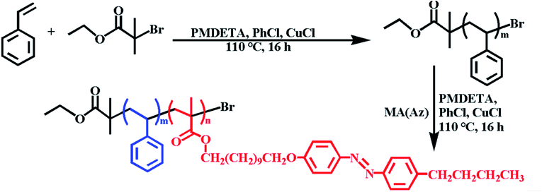
The synthesis of PS-b-PMA(Az) BCPs was achieved by ATRP. As shown in Scheme 1, styrene monomers were polymerized by using ethyl 2-bromoisobutyrate as the initiator, chlorobenzene (PhCl) as solvent and Cu(I)Cl complexed with PMDETA as the catalyst. The obtained PS macroinitiator was then used for the synthesis of PS-b-PMA(Az). The synthetic route to the 11-[4-(4-butylphenylazo)phenoxy]undecyl methacrylate (MA(Az)) monomer was described in a previous publication.46 A series of PSm-b-PMA(Az)n BCPs with different repeating units were synthesized by adjusting the feed ratio of MA(Az)/PS. Typical 1H nuclear magnetic resonance (NMR) spectra of PS and PS-b-PMA(Az) BCPs are shown in Fig. S1.† The number-average molar mass (Mn(NMR)) and degree of polymerization (DP) for the PS and PMA(Az) blocks were calculated from the 1H NMR spectra. In their gel permeation chromatography (GPC) chromatograms (Fig. S2†), all the obtained BCPs exhibit a monomodal peak and low polydispersity index (PDI) values ranging from 1.12 to 1.28. The comparative information about the PS macroinitiators and BCPs is summarized in Table 1.| Sample | M n (NMR, kg mol−1) | M n (GPC, kg mol−1) | M w/Mnc | DPPSd | DPPMA(Az)e | f PS | Morphologyg |
|---|---|---|---|---|---|---|---|
| a Number-average molecular weight determined by NMR. b Number-average molecular weight determined by GPC. c Polydispersity determined by GPC calibrated with polystyrene standards. d Polymerization degree of PS. e Polymerization degree of PMA(Az). f Volume fraction of PS calculated by using the molecular weight and density (PS: 1.05 g cm−3 and PMA(Az): 1.10 g cm−3) of each block. g Morphology of the block copolymer film determined by SEM observations. | |||||||
| PS28 | 2.9 | 3.1 | 1.12 | 28 | — | 1 | — |
| PS42 | 4.4 | 4.7 | 1.12 | 42 | — | 1 | — |
| PS60 | 6.3 | 6.7 | 1.13 | 60 | — | 1 | — |
| PS100 | 10.4 | 11.0 | 1.18 | 100 | — | 1 | — |
| 28-68 | 36.4 | 37.4 | 1.25 | 28 | 68 | 0.083 | Cylinders |
| 42-16 | 12.3 | 13.8 | 1.18 | 42 | 16 | 0.37 | Cylinders |
| 60-15 | 13.7 | 14.8 | 1.20 | 60 | 15 | 0.46 | Cylinders |
| 100-59 | 39.4 | 40.1 | 1.28 | 100 | 59 | 0.27 | Cylinders |
| 100-44 | 32.1 | 33.1 | 1.26 | 100 | 44 | 0.33 | Cylinders |
| 100-35 | 27.6 | 28.2 | 1.25 | 100 | 35 | 0.39 | Cylinders |
| 100-32 | 26.1 | 27.0 | 1.25 | 100 | 32 | 0.41 | Cylinders |
| 100-27 | 23.7 | 24.1 | 1.24 | 100 | 27 | 0.45 | Cylinders |
| 100-24 | 22.2 | 22.9 | 1.23 | 100 | 24 | 0.49 | Cylinders + lamellae |
| 100-22 | 21.2 | 21.8 | 1.23 | 100 | 22 | 0.50 | Lamellae |
| 100-18 | 19.3 | 19.9 | 1.22 | 100 | 18 | 0.55 | Lamellae |
3.2 Liquid crystalline properties of PS-b-PMA(Az) block copolymers
Fig. S3† shows the typical differential scanning calorimetry (DSC) curves of PS-b-PMA(Az) BCPs on their first cooling and second heating processes. All BCPs exhibited a clear endothermic transition at 95–125 °C, attributable to the phase transition between the smectic phase and isotropic phase (Sm–I). The transition temperature increases with increasing LC content. In addition, there were peaks at ∼65 °C and ∼90 °C, which can be assigned to the glass transition temperature (Tg) of PMA(Az) and PS, respectively.47,48 Fig. S4a† shows a polarized optical microscopic (POM) image of PS100-b-PMA(Az)44. The pellet sample was heated to 140 °C and then cooled slowly. The batonnet texture appeared upon cooling to 110–105 °C, corresponding to the smectic LC phase. Therefore, the thermal treatment temperature for the BCPs was fixed at 140 °C, slightly higher than that of the Sm–I transition of the PMA(Az) blocks. The LC phase of the BCPs was further confirmed by wide-angle X-ray diffraction (WAXD) (Fig. S4b†). Before measurement, the samples were thermally annealed at 140 °C for 24 h. There are two peaks at 2θ = 2.74° and 5.48° in the WAXD spectrum, which can be assigned to [001] and [002] diffractions, respectively, coming from the smectic phase LC layer at a periodicity of d001 = λ/(2![[thin space (1/6-em)]](https://www.rsc.org/images/entities/char_2009.gif) sin
sin![[thin space (1/6-em)]](https://www.rsc.org/images/entities/char_2009.gif) θ) = 3.22 nm.
θ) = 3.22 nm.
3.3 Self-assembled nanostructures of PS-b-PMA(Az) thin films
Fig. S5† shows the scanning electron microscopy (SEM) images of PS100-b-PMA(Az)44 films annealed at 140 °C for different times. There is no regular structure formed for the as-prepared film (Fig. S5a and b†). After annealing for 1 min, some stripes and dots can be observed (Fig. S5c and d†). This observation indicates that phase separation began to partly occur because of insufficient motion of the two segments during short-term treatment. When the annealing time was extended to 3 min, more dots can be found (Fig. S5e and f†). Notably, ordered dot patterns appeared, generally after annealing for 5 min at 140 °C (Fig. S5g and h†). Therefore, the annealing procedure of 140 °C for 5 min was selected to ensure the equilibrium morphology of the nanodomains in PS-b-PMA(Az) films.The self-assembled nanostructures of BCP films after thermal annealing at 140 °C for 5 min were characterized by atomic force microscopy (AFM) and transmission electron microscopy (TEM). Fig. 1a and b show the AFM height images of PS100-b-PMA(Az)44 and PS100-b-PMA(Az)22 with fPS values of 0.33 and 0.50, respectively. The bright and dark regions are assigned to PS and PMA(Az) domains, respectively. The dot patterns were observed when fPS = 0.33 (Fig. 1a), indicating vertically aligned PS cylindrical domains surrounded by the PMA(Az) matrix. The average center-to-center distance and the diameter of the PS cylinders are (37.0 ± 1.6) nm and (25.2 ± 1.4) nm, respectively. In Fig. 1b, overall finger-printed patterns formed for PS100-b-PMA(Az)22, suggesting a normally aligned lamellar structure with an average width of (24.0 ± 1.1) nm and a center-to-center distance of (36.1 ± 1.0) nm. In TEM images (Fig. S6†), the bright and dark parts correspond to PMA(Az) and PS microdomains, respectively, due to the selective staining of PS by ruthenium tetroxide (RuO4) vapor. The insets in Fig. S6† are the corresponding fast Fourier transform (FFT) images, further indicating ordered cylindrical and lamellar structures, respectively.
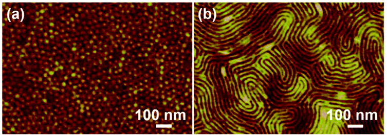 | ||
| Fig. 1 AFM height images of cylindrical PS100-b-PMA(Az)44 (a) and lamellar PS100-b-PMA(Az)22 (b) thin films after thermal annealing at 140 °C for 5 min. | ||
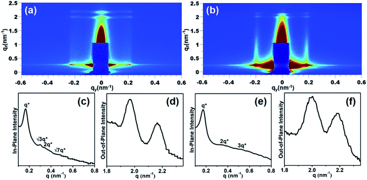
To further evaluate the orientation in a large area, the samples were characterized by grazing-incidence small-angle X-ray scattering (GISAXS) with an incident angle of 0.15°. Fig. 2a and b show the GISAXS images of PS100-b-PMA(Az)44 and PS100-b-PMA(Az)22 films, respectively. Scattering signals in the in-plane and out-of-plane direction appeared, corresponding to the vertical alignment of microphase separated structures and parallel orientation of LC ordering, respectively. Fig. 2c shows the in-plane profile of Fig. 2a. The relative peak positions can be attributed to 1![[thin space (1/6-em)]](https://www.rsc.org/images/entities/char_2009.gif) :
:![[thin space (1/6-em)]](https://www.rsc.org/images/entities/char_2009.gif) √3
√3![[thin space (1/6-em)]](https://www.rsc.org/images/entities/char_2009.gif) :
:![[thin space (1/6-em)]](https://www.rsc.org/images/entities/char_2009.gif) 2
2![[thin space (1/6-em)]](https://www.rsc.org/images/entities/char_2009.gif) :
:![[thin space (1/6-em)]](https://www.rsc.org/images/entities/char_2009.gif) √7, illustrating a hexagonal arrangement with a periodicity of 37.8 nm calculated from the first-order reflection of qxy = 0.166 nm−1. The out-of-plane profile is shown in Fig. 2d, indicating the smectic LC layer structure, with a spacing of 3.22 nm calculated from qxz = 1.95 nm−1. This value is consistent with values from our previous studies.49 The out-of-plane profile is similar to that of PS100-b-PMA(Az)22 films (Fig. 2f), whereas the in-plane profile is quite different. As shown in Fig. 2e, the first-order reflection shifts to 0.174 nm−1 with a periodicity of 36.1 nm. The peaks can be assigned to 1
√7, illustrating a hexagonal arrangement with a periodicity of 37.8 nm calculated from the first-order reflection of qxy = 0.166 nm−1. The out-of-plane profile is shown in Fig. 2d, indicating the smectic LC layer structure, with a spacing of 3.22 nm calculated from qxz = 1.95 nm−1. This value is consistent with values from our previous studies.49 The out-of-plane profile is similar to that of PS100-b-PMA(Az)22 films (Fig. 2f), whereas the in-plane profile is quite different. As shown in Fig. 2e, the first-order reflection shifts to 0.174 nm−1 with a periodicity of 36.1 nm. The peaks can be assigned to 1![[thin space (1/6-em)]](https://www.rsc.org/images/entities/char_2009.gif) :
:![[thin space (1/6-em)]](https://www.rsc.org/images/entities/char_2009.gif) 2
2![[thin space (1/6-em)]](https://www.rsc.org/images/entities/char_2009.gif) :
:![[thin space (1/6-em)]](https://www.rsc.org/images/entities/char_2009.gif) 3, indicating the lamellar structure. The results are in good accordance with those from the AFM and TEM images. It can be concluded that in each case, the LC ordering layers in PMA(Az) blocks are normal to the PS microdomains, leading to a crisscross structure, which is beneficial for rapidly forming vertically aligned microphase-separated structures via mild thermal annealing. The etching rate difference between two blocks is of great importance for transferring patterns in BCP lithographic applications.
3, indicating the lamellar structure. The results are in good accordance with those from the AFM and TEM images. It can be concluded that in each case, the LC ordering layers in PMA(Az) blocks are normal to the PS microdomains, leading to a crisscross structure, which is beneficial for rapidly forming vertically aligned microphase-separated structures via mild thermal annealing. The etching rate difference between two blocks is of great importance for transferring patterns in BCP lithographic applications.
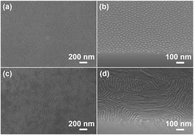
Reactive ion etching (RIE) has been frequently utilized in the microelectronics industry. It is well known that the etching rate of PS is much lower than that of PMMA, which endows PS-b-PMMA with good etching selectivity.50,51 In this study, LC segments were incorporated into PMMA backbones, leading to an etching rate that is slightly slower than that of PMMA but still much faster than that of PS (Fig. S7†). The etching rates of PMA(Az) and PS were also measured. It is 2.8 nm s−1 for PMA(Az), which is ∼1.6 times faster than that of PS (1.7 nm s−1) under 50 W O2/Ar RIE. In other words, the etching rate difference between PS and PMA(Az) is good for this application. Then, we recorded the cylindrical structures of PS100-b-PMA(Az)44 films under different RIE conditions. As shown in Fig. S8,† the microdomains were best imaged after etching with 50 W O2/Ar for 30 s. Clearly, PS cylinders vertically aligned on the substrate after the removal of the PMA(Az) matrix (Fig. S8i and j†). Therefore, the etching conditions were fixed at 50 W O2/Ar RIE for 30 s. Fig. 3 shows the representative top surface and cross-sectional SEM images of PS cylinders and lamellae after RIE. Perpendicularly aligned PS cylinders and lamellae are well maintained after the removal of the PMA(Az) block. For PS cylinders (Fig. 3a and b), the average periodicity and diameter are (37.4 ± 1.5) nm and (25.9 ± 2.0) nm, respectively. The corresponding data for the PS lamellae in Fig. 3c and d are (36.8 ± 1.5) nm and (24.5 ± 1.8) nm, respectively.
Generally, the cylindrical phase window for common coil–coil BCPs is 0.2 ≤ f ≤ 0.35.52,53 In this work, LC segments were incorporated into the side chain of hydrophobic blocks, which is expected to affect the alignment and phase window. A series of BCPs with different compositions were synthesized to investigate their influence on the self-assembled structures, as shown in Fig. S9–S11† and summarized in Table 1. As mentioned above, normal cylinders and lamellae were obtained when fPS = 0.33 and 0.50, respectively. Fig. S9† shows the SEM images of PS100-b-PMA(Az)n films after RIE. It can be seen that ordered cylinders were obtained with fPS values in the range of 0.27–0.45. Accordingly, the diameter of the PS cylinders increased from (22.1 ± 1.1) nm to (26.4 ± 1.2) nm. As fPS continuously increased to 0.49, a lamellar structure, mixed with cylinders, appeared, as clearly characterized in Fig. S10.† Pure lamellae formed when fPS reached 0.55 (Fig. S11†). Microphase separation failed to occur if the PS volume fractions were further increased, especially for the PS100 series. Previously, other PMA(Az)-based block copolymer thin films, including PEO-b-PMA(Az)40 and P4VP-b-PMA(Az)43 were reported. It is difficult to obtain vertically aligned lamellar structures in these systems. Here, PS-b-PMA(Az) films formed perpendicularly aligned both cylinders and lamellae with a definite lamellar phase window.
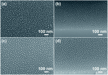
A small feature size is one of the requirements in this field. We tried to decrease the diameter of the PS cylinders by decreasing the molecular weight of the BCPs. Considering the prerequisite of microphase separation, the most effective method is to decrease the number of repeating units in the PS blocks to some extent. For this purpose, PS60-b-PMA(Az)15 (fPS = 0.46), PS42-b-PMA(Az)16 (fPS = 0.37) and PS28-b-PMA(Az)68 (fPS = 0.083) were synthesized. As shown in SEM images, a highly ordered vertical orientation of PS cylinders was obtained after RIE (Fig. 4, S12a and b†). The average diameters of the PS cylinders in PS60-b-PMA(Az)15, PS42-b-PMA(Az)16 and PS28-b-PMA(Az)68 are (18.0 ± 1.2), (15.2 ± 2.1) and (12.0 ± 1.4) nm, respectively. Thus, the cylinder window for PS-b-PMA(Az) is broad (0.083 ≤ fPS < 0.49) with PS cylinders down to ∼12 nm in diameter, which can be further confirmed by TEM images (Fig. S13†).
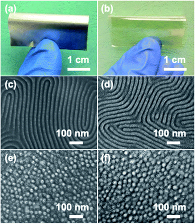
As mentioned above, it is highly desirable to transfer patterns to flexible substrates. Here, cylindrical and lamellar films were also spin-coated onto conductive aluminum foil and transparent PET sheets, as shown in Fig. 5a and b, respectively. The substrates were simply cleaned with ethanol without any other treatment. After RIE, clear lamellar structures and ordered cylindrical PS patterns were obtained on these two flexible substrates (Fig. 5c–f), further illustrating the surface-independence of PS-b-PMA(Az). From the cross-sectional TEM and top-view AFM height images of the annealed PS100-b-PMA(Az)44 film (Fig. S14†), it can be confirmed that PS cylinders perpendicularly span through the film from top to bottom. Therefore, this BCP can be considered a powerful candidate for flexible microelectronic devices.
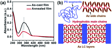
Fig. 6a shows the ultraviolet-visible spectroscopy (UV-vis) spectra of PS100-b-PMA(Az)44 films before and after thermal annealing. Clearly, the absorption maximum of the π–π* transition of the azobenzene units shifts from 337 nm to 326 nm due to the occurrence of H-aggregation upon thermal annealing.54–56 Therefore, the azobenzene chromophore homeotropically aligned upon thermal annealing. This result further reflects the formation of a crisscross structure within PS-b-PMA(Az) films, as schematically illustrated in Fig. 6b. The distinctive structure facilitates the vertical alignment of nanodomains via rapid thermal annealing without preference toward substrates.
4. Conclusions
In summary, we have demonstrated the formation of perpendicularly aligned cylindrical and lamellar nanodomains within PS-b-PMA(Az) films on various non-pretreated substrates via thermal annealing at 140 °C for 5 min. Due to the good etching selectivity between the two blocks, PS normal structures can be successfully fabricated from PS-b-PMA(Az) thin films after RIE. The PS volume fraction for the formation of vertical cylinders is very broad (0.083 ≤ fPS < 0.49). The diameter of the PS cylinders increases with increasing fPS, but the periodicity exhibits the opposite tendency. Lamellae appear when fPS = 0.50–0.55. No microphase-separated structure appears with a continuous increase in the PS fraction. The smallest diameter of the PS cylinders is down to 12 nm. Ordered structures form on either hard surfaces (Si wafer) or flexible ones, such as transparent PET sheets and conductive Al foils, without any pretreatment. The GISAXS and UV-vis results confirm the formation of a distinctive crisscross structure consisting of out-of-plane ordered smectic LC layers and in-plane PS nanodomains upon thermal annealing, which is of great importance for the effective formation of vertical alignment. Thus, PS-b-PMA(Az) films hold great promise for application in the field of flexible microelectronic devices.Conflicts of interest
There are no conflicts to declare.Acknowledgements
This work was financially supported by the National Natural Science Foundation of China (No. 51472018), the Natural Science Foundation of Beijing Municipality (No. 2202024) and the Fundamental Research Funds for the Central Universities. The authors also thank the Shanghai Synchrotron Radiation Facility (SSRF) China for providing the BL16B1 beamline.References
- X. Gu, I. Gunkel and T. P. Russell, Philos. Trans. R. Soc., A, 2013, 371, 1 Search PubMed.
- Y. J. Choi, J. Y. Kim, J. E. Kim, J. H. Mun, S. K. Cha and S. O. Kim, Adv. Funct. Mater., 2016, 26, 6462 CrossRef CAS.
- C. Choi, J. Park, K. L. Vincent Joseph, J. Lee, S. Ahn, J. Kwak, K. S. Lee and J. K. Kim, Nat. Commun., 2017, 8, 1765 CrossRef PubMed.
- C. Cummins, T. Ghoshal, J. D. Holmes and M. A. Morris, Adv. Mater., 2016, 28, 5586 CrossRef CAS PubMed.
- S. W. Hong, J. F. Xia and Z. Q. Lin, Adv. Mater., 2007, 19, 1413 CrossRef CAS.
- S. W. Hong, J. Wang and Z. Q. Lin, Angew. Chem., Int. Ed., 2009, 48, 8356 CrossRef CAS PubMed.
- M. Byun, S. W. Hong, F. Qiu, Q. Z. Zou and Z. Q. Lin, Macromolecules, 2008, 41, 9312 CrossRef CAS.
- Y. D. Luo, D. Montarnal, S. Kim, W. C. Shi, K. P. Barteau, C. W. Pester, P. D. Hustad, M. D. Christianson, G. H. Fredrickson, E. J. Kramer and C. J. Hawker, Macromolecules, 2015, 48, 3422 CrossRef CAS.
- Y. H. Hur, S. W. Song, J. M. Kim, W. I. Park, K. H. Kim, Y. J. Kim and Y. S. Jung, Adv. Funct. Mater., 2018, 28, 1800765 CrossRef.
- J. Kwak, A. K. Mishra, J. Lee, K. S. Lee, C. Choi, S. Maiti, M. Kim and J. K. Kim, Macromolecules, 2017, 50, 6813 CrossRef CAS.
- P. Mansky, C. K. Harrison, P. M. Chaikin, R. A. Register and N. Yao, Appl. Phys. Lett., 1996, 68, 2586 CrossRef CAS.
- S. Park, Y. Kim, W. Lee, S.-M. Hur and D. Y. Ryu, Macromolecules, 2017, 50, 5033 CrossRef CAS.
- C. X. Wang, X. M. Li and H. Deng, ACS Macro Lett., 2019, 8, 368 CrossRef CAS.
- G. Jeong, D. M. Yu, J. K. D. Mapas, Z. W. Sun, J. Rzayev and T. P. Russell, Macromolecules, 2017, 50, 7148 CrossRef CAS.
- Y. Rokhlenko, K. Kawamoto, J. A. Johnson and C. O. Osuji, Macromolecules, 2018, 51, 3680 CrossRef CAS.
- C. Sinturel, F. S. Bates and M. A. Hillmyer, ACS Macro Lett., 2015, 4, 1044 CrossRef CAS.
- L. C. Cheng, K. R. Gadelrab, K. Kawamoto, K. G. Yager, J. A. Johnson, A. A. Katz and C. A. Ross, Nano Lett., 2018, 18, 4360 CrossRef CAS PubMed.
- M. Li and C. K. Ober, Mater. Today, 2006, 9, 30 CrossRef CAS.
- J. Zhang, M. B. Clark, C. Wu, M. Li, P. Trefonas III and P. D. Hustad, Nano Lett., 2016, 16, 728 CrossRef CAS PubMed.
- E. Kim, W. Kim, K. H. Lee, C. A. Ross and J. G. Son, Adv. Funct. Mater., 2014, 24, 6981 CrossRef CAS.
- R. Lundy, S. P. Flynn, C. Cummins, S. M. Kelleher, M. N. Collins, E. Dalton, S. Daniels, M. A. Morris and R. Enright, Phys. Chem. Chem. Phys., 2017, 19, 2805 RSC.
- H.-C. Kim, S.-M. Park and W. D. Hinsberg, Chem. Rev., 2010, 110, 146 CrossRef CAS PubMed.
- W. J. Durand, M. C. Carlson, M. J. Maher, G. Blachut, L. J. Santos, S. Tein, V. Ganesan, C. J. Ellison and C. G. Willson, Macromolecules, 2016, 49, 308 CrossRef CAS.
- D. Y. Ryu, K. Shin, E. Drockenmuller, C. J. Hawker and T. P. Russell, Science, 2005, 308, 236 CrossRef CAS PubMed.
- A. P. Lane, X. M. Yang, M. J. Maher, G. Blachut, Y. Asano, Y. Someya, A. Mallavarapu, S. M. Sirard, C. J. Ellison and C. G. Willson, ACS Nano, 2017, 11, 7656 CrossRef CAS PubMed.
- X. S. Zhang, Q. B. He, Q. Chen, P. F. Nealey and S. X. Ji, ACS Macro Lett., 2018, 7, 751 CrossRef CAS.
- G.-W. Yang, G.-P. Wu, X. X. Chen, S. S. Xiong, C. G. Arges, S. X. Ji, P. F. Nealey, X.-B. Lu, D. J. Darensbourg and Z.-K. Xu, Nano Lett., 2017, 17, 1233 CrossRef CAS PubMed.
- W. Bai, K. Gadelrab, A. Alexander-Katz and C. A. Ross, Nano Lett., 2015, 15, 6901 CrossRef PubMed.
- H. Q. Hu, M. Gopinadhan and C. O. Osuji, Soft Matter, 2014, 10, 3867 RSC.
- K. Aissou, M. Mumtaz, G. Fleury, G. Portale, C. Navarro, E. Cloutet, C. Brochon, C. A. Ross and G. Hadziioannou, Adv. Mater., 2015, 27, 261 CrossRef CAS PubMed.
- S. Jang, K. Lee, H. C. Moon, J. Kwak, J. Park, G. Jeon, W. B. Lee and J. K. Kim, Adv. Funct. Mater., 2015, 25, 5414 CrossRef CAS.
- A. M. Welander, H. M. Kang, K. O. Stuen, H. H. Solak, M. Müller, J. J. de Pablo and P. F. Nealey, Macromolecules, 2008, 41, 2759 CrossRef CAS.
- S. Woo, S. Jo, D. Y. Ryu, S.-H. Choi, Y. Choe, A. Khan, J. Huh and J. Bang, ACS Macro Lett., 2017, 6, 1386 CrossRef CAS.
- X. M. Li, J. Li, C. X. Wang, Y. Y. Liu and H. Deng, J. Mater. Chem. C, 2019, 7, 2535 RSC.
- J. H. Lee, H.-J. Choi, C. H. Lee, S. W. Song, J. B. Lee, D. H. Huh, Y. S. Nam, D. Y. Jeon, H. Lee and Y. S. Jung, ACS Nano, 2018, 12, 8224 CrossRef CAS PubMed.
- L.-Y. Shi, S. Lee, L.-C. Cheng, H. Huang, F. Liao, R. Ran, K. G. Yager and C. A. Ross, Macromolecules, 2019, 52, 679 CrossRef CAS.
- Y. Morikawa, T. Kondo, S. Nagano and T. Seki, Chem. Mater., 2007, 19, 1540 CrossRef CAS.
- M. Sano, S. Nakamura, M. Hara, S. Nagano, Y. Shinohara, Y. Amemiya and T. Seki, Macromolecules, 2014, 47, 7178 CrossRef CAS.
- K. Fukuhara, S. Nagano, M. Hara and T. Seki, Nat. Commun., 2014, 5, 3320 CrossRef.
- H. Komiyama, R. Sakai, S. Hadano, S. Asaoka, K. Kamata, T. Iyoda, M. Komura, T. Yamada and H. Yoshida, Macromolecules, 2014, 47, 1777 CrossRef CAS.
- T. Qu, Y. Zhao, Z. Li, P. Wang, S. Cao, Y. Xu, Y. Li and A. Chen, Nanoscale, 2016, 8, 3268 RSC.
- X. Zheng, Z. Li, Y. Zhao, T. Qu, S. Cao, P. Wang, Y. Li, T. Iyoda and A. Chen, RSC Adv., 2016, 6, 93298 RSC.
- T. Qu, S. Guan, C. Zhang, X. Zheng, Y. Zhao and A. Chen, Soft Matter, 2018, 14, 7107 RSC.
- C. M. Bates, M. J. Maher, D. W. Janes, C. J. Ellison and C. G. Willson, Macromolecules, 2014, 47, 2 CrossRef CAS.
- A. Nunns, J. Gwyther and I. Manners, Polymer, 2013, 54, 1269–1284 CrossRef CAS.
- Y. Tian, K. Watanabe, X. X. Kong, J. Abe and T. Iyoda, Macromolecules, 2002, 35, 3739 CrossRef CAS.
- N. Chen, L. Yan and X. Xie, Macromolecules, 2013, 46, 3544 CrossRef CAS.
- L. Cui, S. Dahmane, X. Tong, L. Zhu and Y. Zhao, Macromolecules, 2005, 38, 2076 CrossRef CAS.
- S. Guan, C. Zhang, W. Wen, T. Qu, X. Zheng, Y. Zhao and A. Chen, ACS Macro Lett., 2018, 7, 358 CrossRef CAS.
- K. Asakawa and T. Hiraoka, Jpn. J. Appl. Phys., 2002, 41, 6112 CrossRef CAS.
- R. A. Farrell, N. Petkov, M. T. Shaw, V. Djara, J. D. Holmes and M. A. Morris, Macromolecules, 2010, 43, 8651 CrossRef CAS.
- F. S. Bates and G. H. Fredrickson, Phys. Today, 1999, 52, 32 CrossRef CAS.
- M. W. Matsen and F. S. Bates, Macromolecules, 1996, 29, 1091 CrossRef CAS.
- E. Verploegen, L. C. McAfee, L. Tian, D. Verploegen and P. T. Hammond, Macromolecules, 2007, 40, 777 CrossRef CAS.
- S. Asaoka, T. Uekusa, H. Tokimori, M. Komura, T. Iyoda, T. Yamada and H. Yoshida, Macromolecules, 2011, 44, 7645 CrossRef CAS.
- Y. Morikawa, S. Nagano, K. Watanabe, K. Kamata, T. Iyoda and T. Seki, Adv. Mater., 2006, 18, 883 CrossRef CAS.
Footnote |
| † Electronic supplementary information (ESI) available. See DOI: 10.1039/d0na00057d |
| This journal is © The Royal Society of Chemistry 2020 |

