 Open Access Article
Graphene templated growth of copper sulphide ‘flowers’ can suppress electromagnetic interference†
Devansh
Sharma
 a,
Aishwarya V.
Menon
b and
Suryasarathi
Bose
 *a
*a
aDepartment of Materials Engineering, Indian Institute of Science, Bangalore 560012, India. E-mail: sbose@iisc.ac.in
bCenter for Nano Science and Engineering, Indian Institute of Science, Bangalore 560012, India
First published on 30th June 2020
Abstract
With increasing usage of electronic gadgets in various fields, the problem of electromagnetic interference (EMI) has become eminent. To suppress this interference, lightweight materials that are non-corrosive in nature and easy to fabricate, design, integrate and process are in great demand. In the present study, we have grown copper sulphide ‘flowers’ on graphene oxide by a facile one pot hydrothermal technique. The growth time of the “flower-like” structure was optimised based on structural (XRD) and morphological analysis (SEM). Then, the as-prepared structures were dispersed in a PVDF matrix using melt blending. The bulk AC electrical conductivity and EMI shielding ability of the prepared composite were assessed, and it was observed that the nanocomposites exhibited an EMI shielding effectiveness up to −25 dB manifesting in 86% absorption of the incoming EM waves at a thickness of only 1 mm. Moreover, it was also observed that addition of hybrid nanoparticles has a better effect on the electromagnetic (EM) shielding performance compared to when the nanoparticles are added separately in terms of both total shielding effectiveness as well as absorption performance. A minimum skin depth of 0.38 mm was observed in the case of the hybrid nanostructure.
1. Introduction
The advent of modern telecommunication has led to the severe issue of cross-talk among nearby devices leading to a new kind of pollution known as the electromagnetic (EM) pollution. Electromagnetic interference (EMI) is encountered during the operations of various programmed or digital devices such as wearable devices, communication satellites, cellular phones and MEMS/NEMS. Due to this interference, malfunctioning in electronic or digital systems occurs.1,2 These high-frequency EM radiations are known to be detrimental to human health as well.2 To alleviate this problem, there is a stringent need to develop materials exhibiting high-performance shielding behaviour over a broad frequency bandwidth.There are two mechanisms through which EM waves can be attenuated, namely, reflection and absorption. The reflection mechanism is a characteristic of conducting metals.3 Metals act as perfect reflectors for the incoming EM radiation due to the presence of abundant free electrons, which creates a zero field inside the metal surface when EM waves interact with the metal. These free electrons tend to generate an opposing field which cancels the incoming EM wave leading to its reflection.4 However, if the EM waves are reflected, the problem of EMI persists as the reflected EM waves still exist in the surroundings and can always harm other unprotected devices. Therefore, it is the absorption mechanism, a characteristic of magnetic metals and dielectric materials, which is of importance in the field of EMI shielding.5,6 To be an ideal EM shield, the material must possess electric and magnetic dipoles which can interact with the electric and magnetic components of EM waves respectively, and they must absorb EM waves (instead of reflecting them) whilst having a broad absorption bandwidth and lightweight characteristics.7–9
Over the years several research studies have been carried out in the field of EM wave absorbers. More recently, conducting polymers and polymer nanocomposites have been explored. Polymers can be processed much easily compared to metals, and their properties can be tuned to develop EM wave absorbers by incorporating suitable fillers. Carbonaceous fillers like carbon nanotubes (MWCNTs), graphene and its derivatives are being used due to their high aspect ratio and excellent electronic properties.10 Although MWCNTs and graphene are conducting, when dispersed in a polymer matrix, they can attenuate the incoming radiation through multiple internal reflections which finally manifests in the absorption of EM waves. Graphene oxide (GO) is another promising material which hosts various functional groups that can be used to graft functional molecules and other nanomaterials, which would further help in attenuation of EM waves. Grafting functional nanoparticles on GO not only ensures much better dispersion of nanoparticles in the polymer matrix but also helps in creating multiple interfaces which act as polarisation centres that attenuate EM waves.11–13
In recent years many semiconducting materials like ZnS, MoS2, etc. have proven to be efficient EM shielding materials apart from conventional magnetic and conducting metals.14–18 Semi-conductors attenuate EM waves predominantly by the polarisation effect. At high frequencies (>1 GHz), magnetic nanoparticles become ineffective in attenuating EM waves since their permeability becomes unity at high frequency due to Snoek's limit.18,19 Therefore, in this work, we have attempted to develop hybrid nanoparticles by combining the electronic properties of two-layered semi-conductors, reduced graphene oxide and copper sulphide (CuS).
CuS has been extensively employed in a wide variety of applications such as solar photovoltaic and plasmonic devices, biomedical sensing, and photo and electrocatalysis as it has a low bandgap.20–24 Different morphologies of copper sulphide such as flower, sheet, and hollow structure have already been reported.25–27 Since copper sulphide has a low bandgap, it is more conducting than traditional metal oxides.11,26,28 In recent years various bio-inspired synthesis methods for developing nanoparticles were also developed.29–31 Herein, we have attempted to grow CuS flowers on rGO sheets using an industrially viable route like the hydrothermal technique under different conditions. The evolution of morphology as a function of time was analysed. After optimising the growth process of rGO–CuS through structural and morphological analysis, the hybrid nanoparticles were incorporated in a PVDF matrix along with MWCNTs by an industrially viable melt blending technique to achieve synergistic EMI shielding efficiency. We also analysed the effect of the as-processed grown CuS flowers clustered on rGO sheets on the EMI shielding efficiency of the final nanocomposite.
2. Experimental section
2.1 Materials
Copper chloride (CuCl2·2H2O) was purchased from SD Fine Chemical Ltd. Thiourea was purchased from Spectrochem Pvt. Ltd. Graphene oxide was procured from BT Corp. Pristine MWCNTs-NC-7000 (length 1.5 μm and diameter 9.5 nm) were procured from Nanocyl, Belgium, and poly(vinylidene difluoride)-Kynar-761 was obtained from Arkema (Mw = 440![[thin space (1/6-em)]](https://www.rsc.org/images/entities/char_2009.gif) 000 g mol−1).
000 g mol−1).
2.2 Synthesis of nanomaterials and nanocomposites
2.3 Characterisation
The structural analysis of the prepared particles was performed by X-ray diffraction using an XPERT Pro PANalytical with a Cu Kα radiation source (λ = 1.5406 Å). To study the room temperature AC conductivity of the samples in the frequency range of 0.1 Hz to 10 MHz, an Alpha-A analyser (Novocontrol, Germany) was used. The EMI shielding property was analysed using an Agilent Vector Network Analyser (VNA) using a Vidyut Yantra Udyog (model no. KU7061 S.N. 2454) waveguide in the Ku band frequency. Raman spectra were recorded using a Horiba LabRam HR Raman spectrometer using a 532 nm laser. Transmission electron microscopy and HAADF micrographs were acquired using a Titan Themis at 300 kV. A Zeiss Ultra 55 FESEM operating at an accelerating voltage of 5 kV was used for analysing the morphologies of the nanoparticles and nanocomposites. For thermal analysis, thermogravimetric analysis (TGA) was carried out using a Q500 from TA Instruments.3. Results and discussion
3.1 Characterisation of ‘flower-like’ CuS and rGO–CuS hybrid structures
XRD patterns were recorded for different CuS samples synthesised at different time intervals (3 h, 6 h and 24 h) as shown in Fig. 3(a). From the graph, it can be concluded that at 3 h the synthesis of CuS was not complete and therefore all the peaks couldn't be indexed to that of the hexagonal phase of CuS. However, at 6 h and 24 h, peaks at 27°, 27.7°, 29°, 31.8°, 32.3°, 46.32°, 47.82°, 52.51°, 55.07° and 59.02° corresponding to (100), (101), (102), (103), (006), (224), (110), (108), (202) and (116) planes respectively were well inferred which confirms the completion of the formation of CuS. The indexed data have good agreement with the JCPDS reference data (JCPDS-06-0464) and confirmed that a pure phase covellite compound was synthesised during the hydrothermal process.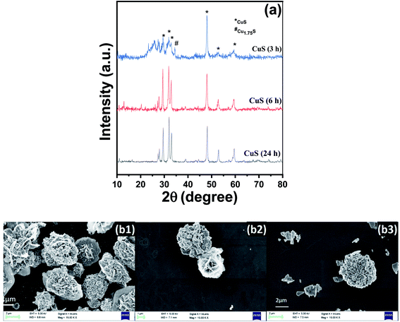 | ||
| Fig. 3 (a) XRD patterns of CuS (3 h), CuS (6 h) and CuS (24 h); SEM micrograph for (b1) CuS (3 h), (b2) CuS (6 h) and (b3) CuS (24 h). | ||
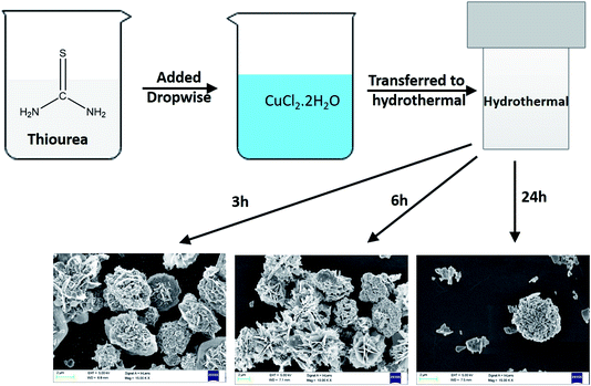
In Fig. 3(b), we can observe the morphological changes in CuS with increasing time from 3 h to 24 h, which echoes with the XRD analysis. The formation of CuS sheets was initiated within 3 h (Fig. 3(b1)) which then assemble to form a flower at the end of 6 h (Fig. 3(b2)). The fully grown petals merge to form clusters at the end of 24 h (Fig. 3(b3)).
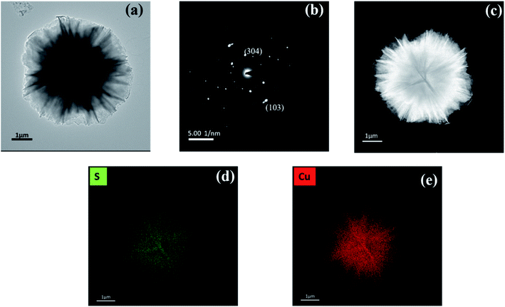
Fig. 4(a) and (c) show bright-field and dark field images respectively of CuS flowers formed due to the agglomeration of various CuS petals into flowers; hence, the transmission is less at the centre, and the centre appears darker. Also, the dimension of the flowers was found to be ca. 2 μm. Fig. 4(b) shows the indexed SAED pattern for CuS flowers which confirms that the crystal structure is HCP. Fig. 4(d) and (e) show the presence of elemental sulphur and copper, respectively.
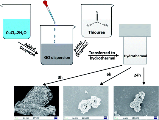
Fig. 5 shows the SEM micrographs of rGO–CuS (3 h), rGO–CuS (6 h) and rGO–CuS (24 h). At 3 h, the nucleation of CuS has started on the surface of GO sheets (see Fig. 5(a) and (b)). However, at 6 h, fully grown CuS flowers can be observed, as seen in Fig. 5(c) and (d). Initially, the CuS sheets are formed and with increase in time the sheets assemble to form a flower-like structure.25 The dimension of the as-prepared flower is estimated to be ca. 4–6 μm, although the size of the petal is about 100 nm. As the duration of hydrothermal treatment increases, the petals grow and fuse, as shown in Fig. 5(e) and (f). Also, it can be inferred from the SEM micrographs that the growth is constrained between the GO sheets. As the duration of hydrothermal treatment increases, petals grow, and deposit on rGO thus covering it completely.
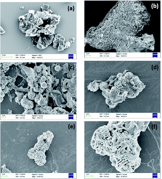 | ||
| Fig. 5 SEM micrograph of (a and b) rGO–CuS (3 h), (c and d) rGO–CuS (6 h), (e and f) rGO–CuS (24 h). | ||
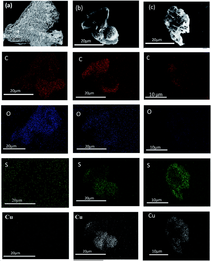
In Fig. 6(a), EDS mapping confirms the presence of Cu and S which increases as time progresses. With increase in time, the CuS sheets start nucleating on the GO sheet and they finally assemble into a flower-like morphology within 6 h as can also be seen from Fig. 6(b). At the end of 24 h, the CuS flowers merge together to from clusters and they completely encapsulate the rGO sheets as seen in Fig. 6(c). It can also be observed from the EDS analysis that the concentration of oxygen decreases with increase in hydrothermal time which confirms the reduction of GO to rGO during hydrothermal treatment.
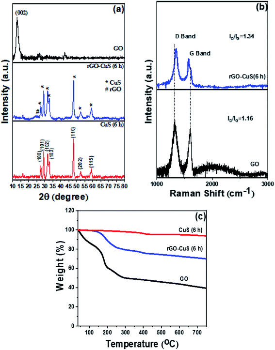
In Fig. 7(a) the 2θ peaks at 27°, 27.7°, 29°, 31.8°, 32.3°, 46.3°, 47.82°, 52.51°, 55.07° and 59.02° corresponding to (100), (101), (102), (103), (006), (224), (110), (108), (202) and (116) reflections respectively of hexagonal CuS are observed which have good agreement with the JCPDS reference data (JCPDS-06-0464). Also, the reduction of GO to rGO can be inferred from the appearance of a broad peak at 24.4°.12 The XRD pattern represents the HCP structure of the as-prepared CuS nanoparticles. In the case of rGO–CuS, the peak corresponding to the (002) plane of graphene oxide (002) at around 12.5° is suppressed, thus confirming the reduction of GO to rGO. Also, it can be inferred that there is no peak other than that of the CuS phase. Thus, the addition of GO does not affect the crystal orientation of CuS. From XRD it was observed that the d-spacing of CuS was 3.19 Å which reduced to 3.04 Å in the case of rGO–CuS. This may be due to insertion of rGO between the CuS sheets. Thus, it can be inferred that the GO sheets act as a nucleating plain for CuS growth.32
Fig. 7(b) shows the Raman spectra of GO, rGO–CuS (6 h) and rGO–CuS (24 h). The Raman spectra display two peaks corresponding to the D band and G band related to the defective and graphitic structures respectively. The intensity of D and G bands (ID/IG) increases from 1.16 in neat GO to about 1.34 after the synthesis of rGO–CuS, which suggests that the defect concentration increases after hydrothermal reduction. Also, there is a shift in the G band in rGO–CuS in comparison to GO, which confirms the formation of Cu–S–C bonds between CuS particles and graphene sheets.33 Taken together, the increase in defect concentration during the synthesis of rGO–CuS and the formation of new bonds can possibly explain the increment in the ID/IG ratio.
Fig. 7(c) shows the TGA thermograms of neat GO, neat CuS and rGO–CuS (6 h). From the TGA we observed multi-step degradation for GO. The initial weight reduction up to 100 °C was attributed to the resorption of physisorbed water. Secondly, in the temperature range of 150–300 °C, the weight loss occurs due to the decomposition of labile oxygen groups. In the third step, we observed weight loss between 300 and 500 °C, which could be attributed to the removal of more stable oxygen groups such as carbonyl, phenol, and quinine. Above 500 °C, pyrolysis of highly stable carbon structures can be well inferred. The percentage grafting of CuS on GO was estimated to be about 17%. From Fig. 7(c), it can be observed that the onset of thermal reduction of GO to as-prepared rGO–CuS begins at 117 °C. As discussed previously, in this work, we have developed nanocomposites where 17 wt% CuS and 83 wt% rGO were incorporated separately (in order to compare with the hybrid structure which contains 17 wt% CuS and 83 wt% rGO) along with MWCNTs to study their effect on the final EMI shielding efficiency.
3.2 Morphology of the nanocomposites
Fig. 8(a) represents the SEM micrographs of the PVDF composite containing 10 wt% rGO–CuS (6 h) and 3 wt% MWCNTs. The melt mixed strands were cryo-fractured, and the samples were sputtered with gold to prevent charging under SEM. From Fig. 8(a) we can infer that the flower-like CuS was embedded in the matrix. In Fig. 8(b) it can be observed that the MWCNTs are well dispersed and are well-percolated at 3 wt% concentration resulting in the formation of a well-interconnected network for effective charge transport. Moreover, the multiple interfaces among these nanoparticles will provide polarisation centres through charge trapping.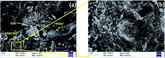 | ||
| Fig. 8 (a) SEM micrographs of PVDF + rGO–CuS (6 h) + MWCNTs (b) magnified image of (a) inset representing the closed connected network of MWCNTs in the polymer matrix. | ||
3.3 Bulk AC electrical conductivity
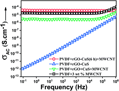
The electrical conductivity of a sample plays a vital role in shielding EM waves. From Fig. 9 it can be inferred that incorporation of only hybrid rGO–CuS in the PVDF matrix resulted in an insulating matrix. Since both rGO and CuS are semiconducting in nature, it is crucial to incorporate a conducting phase like MWCNTs to improve the charge transport efficiency of the nanocomposite. Also, it is known that the conductivity of rGO can vary from semiconducting to conducting depending upon the amount of reduction of oxygen moieties.34 In the case of high aspect ratio fillers like MWCNTs, for efficient charge transport and EMI shielding, interconnectivity between the neighbouring MWCNTs plays a vital role. Addition of a conducting filler like MWCNTs to the polymer matrix has no influence on the conductivity of the composite until the filler forms a percolated conductive pathway within the matrix. MWCNTs, owing to their high aspect ratio achieve percolation at a lower concentration of about 0.5–1 wt% (see Fig. S3†). Although a well-percolated network is not a prerequisite for EMI shielding, better charge transport through an interconnected network results in higher shielding efficiency. The conductivity of a polymer/MWCNT composite scales as a function of MWCNT concentration. From Fig. 9 it can be seen that incorporation of 3 wt% MWCNTs resulted in a completely percolated nanocomposite. However, incorporation of MWCNTs along with rGO–CuS did not seem to hamper the overall conductivity of the nanocomposite. Moreover, in nanocomposites where rGO and CuS were added separately along with MWCNTs, conductivity was lower by an order of magnitude.To gain insight into the charge transport in the matrix, the conductivity data are further analysed by fitting the power law:35
| σac = σ(0) + σac(ω) = σdc + Aωn | (1) |
Table 1 presents the exponents for various nanocomposites. Since nanocomposites containing only rGO–CuS are insulating, the value of the exponent was close to 1 indicating 100% capacitive charge transport. With incorporation of 3 wt% MWCNTs, the value of the exponent decreases to 0.83 indicating 17% resistive and 83% capacitive charge transport. The composites containing separately incorporated rGO and CuS with MWCNTs showed a similar trend. In composites containing the hybrid along with MWCNTs, the value of the exponent decreases to 0.80 indicating about 20% resistive and 80% capacitive charge transport. Therefore, we can conclude that with the addition of MWCNTs in the composite, conduction through tunnelling increases, which translates into better EMI shielding properties.
| Sample | n |
|---|---|
| MWCNTs | 0.83 |
| rGO–CuS (6 h) + MWCNTs | 0.80 |
| rGO + CuS (6 h) + MWCNTs | 0.85 |
| rGO–CuS | 0.99 |
3.4 EMI shielding ability of the composites
The incoming EM waves that interact with the shielding material get attenuated due to reflection, absorption and multiple reflections. The primary shielding occurs due to reflection (SER) from the conducting surface, which arises due to impedance mismatch. Other mechanisms include absorption (SEA) which occurs primarily in magnetic particles and results in heat generation due to various factors and losses. Multiple reflections (SEMR) mainly occur due to successive reflections from the different conducting interfaces within the matrix. The contribution of multiple reflections to shielding is negligible if absorption loss is greater than 10 dB or the thickness of the sample is greater than the skin depth. Therefore, the SET can be expressed as follows:36,37| SET = SEA + SER + SEMR | (2) |
Thus, in general, the above equation can be modified as
| SET = SEA + SER | (3) |
The total shielding effectiveness (SET) is calculated using:
 | (4) |
However, experimentally SET is calculated using scattering parameters obtained from a vector network analyser (VNA) by using the below-stated relationships,
 | (5) |
 | (6) |
 | (7) |
To study EMI shielding, nanocomposites were compression moulded to 1 mm thick sheets using rGO–CuS (6 h) and rGO–CuS (24 h) separately. Since the EMI shielding properties increase with increasing interfaces, rGO–CuS (3 h) is expected to show less shielding efficiency as CuS was just initiated to grow over the rGO surface and hence, less interfaces are present. The results of nanocomposites containing rGO–CuS (24 h) have been discussed in the ESI in Fig. S5.†
Fig. 10(a) represents the total shielding effectiveness for the prepared samples. The composites containing only MWCNTs show EM shielding effectiveness of −20 dB at 18 GHz. The EM energy loss in the MWCNTs can be attributed to inter-tube polarisation, ohmic loss and presence of defects.39 We also observed that the EMI shielding property of the composite increases after addition of MWCNTs from −19 dB in composites with only rGO–CuS to −25 dB in the case of rGO–CuS (6 h) +MWCNTs. In the composite where all the nanoparticles were added separately (rGO + CuS + MWCNTs) the EMI shielding efficiency was −22 dB which was lower than that of the hybrid nanostructure. This could be due to agglomeration of MWCNTs and the small interfacial region between rGO and CuS particles.
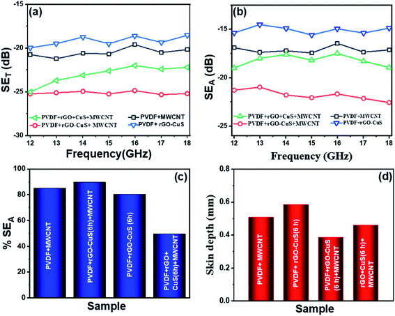 | ||
| Fig. 10 (a) Total shielding effectiveness (SET), (b) SEA parameter, (c) % absorption, (d) skin depth for MWCNTs, rGO–CuS (6 h), rGO–CuS (6 h) + MWCNTs and rGO + CuS (6 h) + MWCNTs. | ||
Fig. 10(b) shows the shielding effectiveness due to absorption for the prepared composites. We can see that the absorption for rGO–CuS is −14.8 dB and −17.2 dB for pristine MWCNTs at 18 GHz. MWCNTs show higher absorption due to multiple internal reflection within the network of MWCNTs which manifests as absorption in the final EMI shielding data. After addition of MWCNTs in rGO–CuS the absorption increased to −22.5 dB which can be attributed to increase in the interfaces between MWCNTs and rGO–CuS thus manifesting in loss due to interfacial polarization and reflection at multiple interfaces. However, as in the case of SET for composites where the nanoparticles were added separately, the absorption loss was observed to be −18.9 dB.
Fig. 10(c) shows the percent absorption for composites with only MWCNTs as 85% while that of composites with only rGO–CuS was 80%. With the incorporation of MWCNTs along with rGO–CuS the absorption percentage increases to 89%. As was also evident from previous data, for composites where the nanoparticles were added separately, the % absorption achieved was 86% which was lower in comparison to that of the hybrid structure.
Fig. 10(d) shows the skin depth (δ) for various composites. Skin depth is a material property. It is defined as the distance travelled by the EM wave in a material to get attenuated by 1/e of its original intensity. The skin depth of a material can be evaluated using:
 | (8) |
 | (9) |
3.5 Mechanism of EM shielding
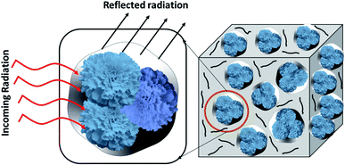
It is estimated that with the increase in the content of MWCNTs, the shielding efficiency increases as they provide a better conducting pathway for efficient charge transport and also absorb the EM waves due to multiple internal reflection within the MWCNT network. The addition of MWCNTs in the rGO–CuS composite increases the conductivity, and results in higher EM shielding efficiency. Although adding semiconducting particles in addition to the rGO and CuS in the composite hinders the conductivity, it also causes multiple reflections at the interface due to impedance mismatch which leads to EM absorption.The energy of the incident EM wave is dissipated in the form of heat, which is attributed to a loss in the magnetic as well as the electric field. The power dissipated per unit volume is expressed as
 | (10) |
 and
and 
Eqn (10) describes loss due to the interaction of the material with the magnetic and electric components of the incident EM waves. When EM radiation interacts with the matter, magnetic loss can occur in the system due to eddy current loss, hysteresis loss and resonance loss (domain wall resonance and electron spin resonance). An alternating magnetic field forces the magnetic dipole to align along the field due to which lot of energy is lost in the form of heat, but at microwave or higher frequency the magnetic dipoles are unable to cope with the alternating field, and hence, losses due to resonance become insignificant at such higher frequencies. A conducting material in a magnetic field experiences loss due to eddy current generation which is prominent in our case because of the presence of MWCNTs and rGO.
Electric loss occurs due to dielectric heating of the material which happens when the alternating electric fields interact with polar materials or ions present in the material. A similar phenomenon occurs during dielectric loss as in magnetic loss. When an alternating electric field interacts with dipoles present in the material, they try to align themselves according to the electric field, but in the process, they collide with each other and tend to lose energy in the form of heat. In the case of a conductor or semiconducting material like CuS, rGO and MWCNTs electrons move back and forth in response to the varying electric field creating an electric current. Also, in the process, the electrons collide with each other as well as with neighbouring atoms and molecules contributing towards dielectric losses.
Apart from these primary losses, there are other factors also which contribute to loss in the case of MWCNTs and rGO. MWCNTs being high aspect ratio particles tend to entangle and form a well-percolated structure. Incoming EM waves suffer multiple reflections from the conducting MWCNTs within a network and thus lose their energy. In the case of rGO, the conductivity depends on the extent of reduction of GO. Also, the reduced graphene oxide has many dipoles due to C–O bonds as well as the carbon element which interacts with EM waves resulting in higher EM loss (Fig. 11).
4. Conclusions
In summary, we have studied the mechanism of growth for a hybrid structure using rGO and CuS as a function of time and studied its influence on EMI shielding. In this study, we have synthesised CuS flowers on an rGO template with nanosized petals using the hydrothermal technique with varying time intervals of 3 h, 6 h and 24 h. XRD analysis shows that pure phase CuS developed at the end of 6 h. The prepared particles were melt mixed with a PVDF matrix, and the conductivity and EMI shielding property were analyzed for the composites. The particles synthesised in varying times under hydrothermal conditions evolve with different morphologies, thus affecting the EMI shielding ability. We have also stressed why the incorporation of hybrid nanoparticles is beneficial compared to addition of individual entities. The hybrid nanoparticles showed better performance in terms of high EM shielding performance of −25 dB with an absorption performance of more than 89%. The skin depth of the prepared composites was also as low as 380 μm.Conflicts of interest
There are no conflicts to declare.Acknowledgements
The author would like to acknowledge DST for funding research and CeNSE, IISc for extending their instrument facility for research.References
- D. He, Y. Xie, X. Wang and Z. Zhang, Significantly Enhanced Electromechanical Performance of PDMS Crosslinked PVDF Hybrids, Polymers, 2018, 10(7), 714 CrossRef PubMed.
- O. P. Gandhi and A. Riazi, Absorption of millimeter waves by human beings and its biological implications, IEEE Trans. Microwave Theory Tech., 1986, 34(2), 228–235 CrossRef.
- X. Luo and D. Chung, Electromagnetic interference shielding using continuous carbon-fiber carbon-matrix and polymer-matrix composites, Composites, Part B, 1999, 30(3), 227–231 CrossRef.
- J. Sun, W. Wang and Q. Yue, Review on microwave-matter interaction fundamentals and efficient microwave-associated heating strategies, Materials, 2016, 9(4), 231 CrossRef PubMed.
- N. Joseph, S. K. Singh, R. K. Sirugudu, V. R. K. Murthy, S. Ananthakumar and M. T. Sebastian, Effect of silver incorporation into PVDF-barium titanate composites for EMI shielding applications, Mater. Res. Bull., 2013, 48(4), 1681–1687 CrossRef CAS.
- G. P. Kar, S. Biswas and S. Bose, Tuning the microwave absorption through engineered nanostructures in co-continuous polymer blends, Mater. Res. Express, 2016, 3(6), 064002 CrossRef.
- J. Huo, L. Wang and H. Yu, Polymeric nanocomposites for electromagnetic wave absorption, J. Mater. Sci., 2009, 44(15), 3917–3927 CrossRef CAS.
- A. V. Menon, G. Madras and S. Bose, Magnetic Alloy-MWNT Heterostructure as Efficient Electromagnetic Wave Suppressors in Soft Nanocomposites, ChemistrySelect, 2017, 2(26), 7831–7844 CrossRef CAS.
- A. V. Menon, G. Madras and S. Bose, Phase specific dispersion of functional nanoparticles in soft nanocomposites resulting in enhanced electromagnetic screening ability dominated by absorption, Phys. Chem. Chem. Phys., 2017, 19(1), 467–479 RSC.
- A. Gebrekrstos, S. Biswas, A. V. Menon, G. Madras, P. Pötschke and S. Bose, Multi-layered stack consisting of PVDF nanocomposites with flow-induced oriented MWCNT structure can supress electromagnetic radiation, Composites, Part B, 2019, 166, 749–757 CrossRef CAS.
- N. Li, G. W. Huang, Y. Q. Li, H. M. Xiao, Q. P. Feng, N. Hu and S. Y. Fu, Enhanced microwave absorption performance of coated carbon nanotubes by optimizing the Fe3O4 nanocoating structure, ACS Appl. Mater. Interfaces, 2017, 9(3), 2973–2983 CrossRef CAS PubMed.
- A. V. Menon, G. Madras and S. Bose, Shape memory polyurethane nanocomposites with porous architectures for enhanced microwave shielding, Chem. Eng. J., 2018, 352, 590–600 CrossRef CAS.
- A. V. Menon, G. Madras and S. Bose, Ultrafast Self-Healable Interfaces in Polyurethane Nanocomposites Designed Using Diels–Alder “Click” as an Efficient Microwave Absorber, ACS Omega, 2018, 3(1), 1137–1146 CrossRef CAS PubMed.
- Y. Wang, D. Chen, X. Yin, P. Xu, F. Wu and M. He, Hybrid of MoS2 and Reduced Graphene Oxide: A Lightweight and Broadband Electromagnetic Wave Absorber, ACS Appl. Mater. Interfaces, 2015, 7(47), 26226–26234 CrossRef CAS PubMed.
- C.-J. Chang and K.-W. Chu, ZnS/polyaniline composites with improved dispersing stability and high photocatalytic hydrogen production activity, Int. J. Hydrogen Energy, 2016, 41(46), 21764–21773 CrossRef CAS.
- A. V. Menon, B. Choudhury, G. Madras and S. Bose, ‘Trigger-free’ self-healable electromagnetic shielding material assisted by co-doped graphene nanostructures, Chem. Eng. J., 2020, 382, 122816 CrossRef CAS.
- A. V. Menon, G. Madras and S. Bose, Mussel-Inspired Self-Healing Polyurethane with “Flower-like” Magnetic MoS2 as Efficient Microwave Absorbers, ACS Appl. Polym. Mater., 2019, 1(9), 2417–2429 CrossRef CAS.
- A. V. Menon, G. Madras and S. Bose, Light weight, ultrathin, and “thermally-clickable” self-healing MWNT patch as electromagnetic interference suppressor, Chem. Eng. J., 2019, 366, 72–82 CrossRef CAS.
- K. Sushmita, A. V. Menon, S. Sharma, A. C. Abhyankar, G. Madras and S. Bose, Mechanistic Insight into the Nature of Dopants in Graphene Derivatives Influencing Electromagnetic Interference Shielding Properties in Hybrid Polymer Nanocomposites, J. Phys. Chem. C, 2019, 123(4), 2579–2590 CrossRef CAS.
- C. Coughlan, M. Ibanez, O. Dobrozhan, A. Singh, A. Cabot and K. M. Ryan, Compound copper chalcogenide nanocrystals, Chem. Rev., 2017, 117(9), 5865–6109 CrossRef CAS PubMed.
- S. Goel, F. Chen, E. B. Ehlerding and W. Cai, Intrinsically radiolabeled nanoparticles: an emerging paradigm, Small, 2014, 10(19), 3825–3830 CrossRef CAS PubMed.
- Z. Zhao, X. Peng, X. Liu, X. Sun, J. Shi, L. Han, G. Li and J. Luo, Efficient and stable electroreduction of CO2 to CH4 on CuS nanosheet arrays, J. Mater. Chem. A, 2017, 5(38), 20239–20243 RSC.
- M. Nair, L. Guerrero and P. Nair, Conversion of chemically deposited CuS thin films to and by annealing, Semicond. Sci. Technol., 1998, 13(10), 1164 CrossRef CAS.
- P. Roy and S. K. J. C. Srivastava, Nanostructured copper sulfides: synthesis, properties and applications, CrystEngComm, 2015, 17(41), 7801–7815 RSC.
- I. Grozdanov and M. Najdoski, Optical and electrical properties of copper sulfide films of variable composition, J. Solid State Chem., 1995, 114(2), 469–475 CrossRef CAS.
- L. Dong, X. Li, D. Xiong, B. Yan, H. Shan and D. Li, Design of a flower-like CuS nanostructure via a facile hydrothermal route, Mater. Technol., 2016, 31(9), 510–516 CrossRef CAS.
- J. Kundu and D. Pradhan, Controlled synthesis and catalytic activity of copper sulfide nanostructured assemblies with different morphologies, ACS Appl. Mater. Interfaces, 2014, 6(3), 1823–1834 CrossRef CAS PubMed.
- Y. Li, W. Lu, Q. Huang, C. Li and W. Chen, Copper sulfide nanoparticles for photothermal ablation of tumor cells, Nanomedicine, 2010, 5(8), 1161–1171 CrossRef CAS PubMed.
- D. Wang, Y. Ha, J. Gu, Q. Li, L. Zhang and P. Yang, 2D Protein Supramolecular Nanofilm with Exceptionally Large Area and Emergent Functions, Adv. Mater., 2016, 28(34), 7414–7423 CrossRef CAS PubMed.
- R. Liu, J. Zhao, Q. Han, X. Hu, D. Wang, X. Zhang and P. Yang, One-Step Assembly of a Biomimetic Biopolymer Coating for Particle, Surf. Eng., 2018, 30(38), 1802851 Search PubMed.
- Y. Djohan, T. Azukizawa, K. Sakai, Y. Yano, F. Sato, R. Takahashi, M. Yohda, M. Maeda, N. Kamiya and T. Zako, Molecular chaperone prefoldin-assisted biosynthesis of gold nanoparticles with improved size distribution and dispersion, Biomater. Sci., 2019, 7(5), 1801–1804 RSC.
- K. Chang and W. Chen, l-Cysteine-Assisted Synthesis of Layered MoS2/Graphene Composites with Excellent Electrochemical Performances for Lithium Ion Batteries, ACS Nano, 2011, 5(6), 4720–4728 CrossRef CAS PubMed.
- N. A. Zubir, C. Yacou, J. Motuzas, X. Zhang and J. C. D. Da Costa, Structural and functional investigation of graphene oxide–Fe3O4 nanocomposites for the heterogeneous Fenton-like reaction, Sci. Rep., 2014, 4, 4594 CrossRef PubMed.
- Y. Bagbi, A. Sarswat, D. Mohan, A. Pandey and P. R. Solanki, Lead and chromium adsorption from water using L-cysteine functionalized magnetite (Fe3O4) nanoparticles, Sci. Rep., 2017, 7(1), 7672 CrossRef PubMed.
- A. K. Jonscher, The ‘universal’dielectric response, Nature, 1977, 267(5613), 673 CrossRef CAS.
- S. P. Pawar, S. Biswas, G. P. Kar and S. Bose, High frequency millimetre wave absorbers derived from polymeric nanocomposites, Polymer, 2016, 84, 398–419 CrossRef CAS.
- S. Geetha, K. Satheesh Kumar, C. R. Rao, M. Vijayan and D. Trivedi, EMI shielding: Methods and materials—A review, J. Appl. Polym. Sci., 2009, 112(4), 2073–2086 CrossRef CAS.
- P. Saini and M. Arora, Microwave absorption and EMI shielding behavior of nanocomposites based on intrinsically conducting polymers, graphene and carbon nanotubes, New Polym. Spec. Appl., 2012, 3, 73–112 Search PubMed.
- S. Biswas, G. P. Kar and S. Bose, Engineering nanostructured polymer blends with controlled nanoparticle location for excellent microwave absorption: a compartmentalized approach, Nanoscale, 2015, 7(26), 11334–11351 RSC.
- M. H. Al-Saleh and U. Sundararaj, Electromagnetic interference shielding mechanisms of CNT/polymer composites, Carbon, 2009, 47(7), 1738–1746 CrossRef CAS.
Footnote |
| † Electronic supplementary information (ESI) available: XRD analysis of rGO–CuS (24 h) and rGO–CuS (3 h). Raman analysis of rGO–CuS (24 h). Electrical conductivity of the control sample containing rGO, CuS, and MWCNTs. EMI shielding ability of the control sample containing rGO, CuS and MWCNTs. See DOI: 10.1039/d0na00368a |
| This journal is © The Royal Society of Chemistry 2020 |

