DOI:
10.1039/D0NA00727G
(Review Article)
Nanoscale Adv., 2020,
2, 5555-5566
Recent progress of Ni–Fe layered double hydroxide and beyond towards electrochemical water splitting
Received
30th August 2020
, Accepted 6th October 2020
First published on 6th October 2020
Abstract
The electrochemical water splitting process including the hydrogen evolution reaction (HER) and oxygen evolution reaction (OER) is considered as one of the most promising methods for high-purity hydrogen production. Ni–Fe based compounds, especially Ni–Fe layered double hydroxide (LDH), have become highly efficient electrocatalysts to expedite the above reactions. During the last decade, great progress has been witnessed in the development of Ni–Fe based electrocatalysts. Diverse regulatory strategies such as morphology modulation, composition control, and defect engineering have been employed to optimize their electrochemical performances for water splitting. In addition, the family of Ni–Fe based compounds has been expanded from LDHs to alloys, sulfides, phosphides and so forth. Deep experimental investigations and theoretical studies have also been carried out to reveal the intrinsic origin of the superior electrocatalytic performances. In this review, we summarise the recent development of Ni–Fe based compounds for electrochemical water splitting with high efficiency. Special focus has been placed on the design principle and synthetic strategies of Ni–Fe based compounds. In the end, remaining challenges and future research directions are briefly discussed.
1. Introduction
Over the past few decades, the global energy demand has continued to grow rapidly.1 Meanwhile, the combustion of traditional fuels such as coal, natural gas, and oil has adversely affected the climate and environment. The resultant global warming issue has become a huge threat to human life.2 As a renewable and clean energy carrier, hydrogen has triggered extensive attention to solve the energy and environment crises. Of note, its high energy density and harmless combustion products make hydrogen the best energy carrier to substitute traditional fossil fuels. At present, commercial hydrogen production is realized through costly steam reforming, which leads to high carbon dioxide emission.3–5 Therefore, an environmentally friendly technology for producing high-purity hydrogen on a large scale is urgently needed.6
Electro-driven water splitting is a prospective method to achieve high-purity hydrogen production without secondary pollution.7 Apart from the hydrogen evolution reaction (HER), water electrolysis also involves the oxygen evolution reaction (OER).8–12 The corresponding HER/OER equations under different conditions are shown below where * represents the active site on the catalyst surface.
HER:
Under acidic conditions:
Under alkaline conditions:
| | | H2O + e− + * → H* + OH− | (3) |
| | | H* + H2O + e− → H2 + OH− + * | (4) |
OER:
Under acidic conditions:
| | | H2O + * → HO* + H+ + e− | (5) |
| | | O* + H2O → HOO* + H+ + e− | (7) |
| | | HOO* → * + O2 + H+ + e− | (8) |
Under alkaline conditions:
| | | HO* + OH− → O* + H2O + e− | (10) |
| | | HOO* + OH− → * + O2 + H2O + e− | (12) |
As shown above, water molecules or hydroxide ions are oxidized at the anode to generate oxygen gas. Meanwhile, the reduction reaction occurs at the cathode to produce hydrogen gas. These gases can be used in fuel cells and converted back into electrical energy.13 Theoretically, a thermodynamic potential of 1.23 V is necessary under standard conditions to drive water electrolysis. However, huge overpotential (η) is required under practical conditions to overcome the polarization and realize the adsorption/desorption of the reactants/products.14 Therefore, highly active electrocatalysts are always needed to facilitate the HER/OER at both ends. Pt has been considered the best choice for the HER due to the moderate binding energy with hydrogen,15 whereas IrO2 and RuO2 are believed to be the best candidates for the OER due to favorable binding energies of oxygen and hydroxyl radicals.16 Because of the high price and low reserves of the above-mentioned precious metals, many research studies are devoted to exploring cost-effective, high-performance, high-stability electrocatalysts.17–20
Transition metal (Mn, Fe, Co, and Ni) compounds, especially oxides or hydroxides, are considered to be potential candidates for OER/HER electrocatalysts because of their abundant resources, low cost, and plenty of active sites.21–23 Among them, under alkaline conditions, the layered double hydroxide (LDH) has nickel hydroxide with tailorable phases, which can show low η toward the OER.24 Introduction of an appropriate amount of Fe impurities could largely enhance the OER activity of Ni species because the synergistic effect brings better surface adsorption and faster electron transfer. Compared with other electrocatalysts, the low cost and reasonable binding energies to OOH* and OH* make Ni–Fe based compounds good candidates for the OER in alkaline solution.15 Similarly, Ni–Fe based alloys, sulfides and phosphides have demonstrated certain advantages among various HER electrocatalysts owing to high conductivity and appropriate hydrogen adsorption free energy with competitive prices.25,26
In this review, we sum up the recent development of Ni–Fe based compounds for the electron driven HER and OER. Special focus has been placed on the design strategies and synthetic methods for Ni–Fe LDH, alloys, sulfides, and phosphides (Fig. 1). In the final part, we briefly discuss the current challenges and future directions in this research area.
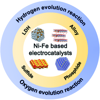 |
| | Fig. 1 Schematic illustration of advanced Ni–Fe based electrocatalysts. | |
2. Design strategies for Ni–Fe based compounds for electrocatalysts
No matter for the two-electron HER or four-electron OER, it is always essential for electrocatalysts to promote the intrinsic activity of the actives sites and expose more active sites on the surface.27–30 Although some strategies are universal, specific tactics and detailed obstacles vary for different kinds of Ni–Fe based compounds. Ni–Fe LDHs have long been considered to be promising OER electrocatalysts, however, the conductivity is an intractable issue for performance optimization.21 For Ni–Fe alloys, potential agglomeration during the catalyst preparation and circulation is harmful to practical utilization.31 Ni–Fe sulfides/phosphides have good conductivity for the HER, nevertheless, the possible phase-transformation makes them vulnerable in the OER.32 Benefitting from the development of nanotechnology and synthetic/characteristic methodologies, numerous Ni–Fe based compounds with distinct features have been synthesized and studied for electrocatalytic water splitting.33 Hollow/porous micro-/nanostructures are proven to be effective structural designs to improve the electrode–electrolyte contact area for more electroactive sites.34 Hybrids with conductive substrates could further accelerate the electron transport for fast kinetics.24 Defect/strain/phase engineering at the surface could inherently alter the physico-chemical properties of individual active sites by changing the binding energies of different intermediates or interfacial electron transfer.35–37 In the following sections, we will highlight some representatives of typical Ni–Fe based compounds for water electrolysis.38,39
3. Ni–Fe LDHs
Ni–Fe LDHs are a typical class of two-dimensional (2D) layered nanosheets composed of a brucite-like host layer of nickel oxide octahedra coordinated by hydroxyl groups with a fraction of Fe2+/Fe3+ substituting at Ni sites. The excess positive charges are balanced by exchangeable charge-balancing interlayer anions.40 Ni–Fe LDH is very attractive for the OER due to the synergistic effect between Ni and Fe elements. Besides, the ultrathin feature provides shortened electron diffusion length. However, its intrinsic poor electron/ion conductivity limits the electrocatalytic performance. Moreover, restacking of LDH nanosheets might occur during cycles, resulting in the decay of electrocatalytic activities.41,42 Various structural and compositional modulation strategies could be applied to address the above issues for Ni–Fe LDH.
Hollow micro-/nanostructures with a large surface area and void space could effectively promote the contact between the electrolyte and electrode for more active sites.43–45 The versatile synthetic routes and tailorable templates enable the diversity of the architecture and compositions of hollow structured Ni–Fe LDH. Simple hollow or multi-shelled Ni–Fe LDH hollow electrocatalysts with tailorable Ni/Fe ratios have been reported.34,46 Moreover, integration of nanostructures and microstructures can enhance the structural stability of the electrocatalysts to maintain the catalytic performance during the repeated cycles.47,48 For instance, Yu et al. reported the formation of hollow nanoprisms constructed from ultrathin Ni–Fe LDH nanosheets using a self-templated method.46 As depicted in Fig. 2a, water-soluble nickel precursors serve as both a template and reactant in the formation of Ni–Fe LDH. During the hydrolysis of iron(II) sulfate in aqueous solution, the released Ni2+ forms a precipitate with Fe2+ to generate a hierarchical ultrathin layer of Ni–Fe LDH on the internal template. Due to the continued consumption from the water and hydrolysis, the Ni-based core is gradually etched to leave a void inside. As the final stage a hierarchical prism-like hollow structure of Ni–Fe LDH with a tailorable Ni/Fe ratio could be obtained. During the self-templated process, no hard template is involved. Therefore, the redundant template removal step under harsh chemical or physical environments is avoided. Moreover, the self-engaged templates should be quite uniform to ensure the quality of the obtained sample. The field-emission scanning electron microscopy (FESEM) observation demonstrates the uniform distribution of the prism-like structure composed of randomly oriented nanosheets (Fig. 2b). Transmission electron microscopy (TEM) investigation shows a clear bright contrast between the outer shell and well-demarcated internal void, indicating the hollow nature of Ni–Fe LDH nanoprisms (Fig. 2c). In addition, a set of clear lattice fringes separated by 0.26 nm can be identified in the high-resolution TEM image, demonstrating the LDH structure of the hierarchical shell (Fig. 2d). In order to evaluate the electrochemical performance, the research team conducted an OER performance test on Ni–Fe LDH with a three-electrode system. During the tests, KOH solution under the protection of N2 is selected as the electrolyte. The linear sweep voltammetry (LSV) curve (Fig. 2e) indicates that the synthesized Ni–Fe LDH hollow nanoprism needs a low η of 280 mV at 10 mA cm−2 and a corresponding Tafel slope of 49.4 mV dec−1 (Fig. 2f). In addition, a redox peak at 1.4 V is observed, indicating the change in the oxidation state of nickel species from bivalent to trivalent. As for the stability test, continuous cyclic voltammetry (CV) scans before and after 1000 cycles are performed. The results show only a small shift at j = 10 mA cm−2 for the Ni–Fe LDH hollow nanoprism (Fig. 2g).
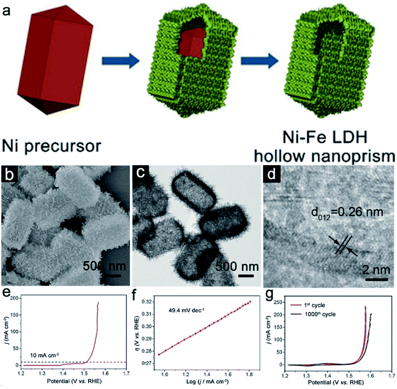 |
| | Fig. 2 (a) Schematic diagram of the formation of Ni–Fe LDH hollow nanoprisms. (b) FESEM, (c) TEM, and (d) HRTEM images of the Ni–Fe LDH hollow nanoprisms. (e) LSV and (f) Tafel curves for the Ni–Fe LDH hollow prisms. (g) CV plots of the Ni–Fe LDH sample before and after cycles. Reproduced with permission.46 Copyright 2018, John Wiley & Sons, Inc. | |
For the conductivity issue, researchers usually choose to combine Ni–Fe LDH with a conductive medium to facilitate the electron transfer, such as carbon nanotubes,49 carbon frames,26 graphene,12 and metals such as Au,50 Cu,4 and Ru.9 Besides the reduction of resistivity, the incorporation of the conductive auxiliaries could provide extra assistance for the OER performance through the interactions. For example, Zhang et al. systematically investigated the effects of single Au atoms on the OER performance of Ni–Fe LDH.50 Different from the traditional doping or hybrid, the single atoms with high atomic utilization efficiency could not only largely reduce the usage of heteroatoms, but also could provide a potential solution to verify the detailed function of the heteroatom.51 Theoretical investigations reveal that the abundant active sites of sAu/Ni–Fe LDH may be attributed to the Fe atom in Ni–Fe oxyhydroxide and stabilized by the CO32− anion and H2O between the cation layers. Then, single-atom Au loading changed the charge redistribution of the surrounding atoms, further resulting in excellent OER activity (Fig. 3a). This theoretical discovery is also proved in subsequent experimental tests. High-angle annular dark field-scanning transmission electron microscopy (HAADF-STEM) reveals the successful loading of single Au atoms on the surface of Ni–Fe LDH (Fig. 3b). X-ray absorption near edge structure (XANES) spectra indicate the different Au atomic local structural environments for sAu/Ni–Fe LDH and Au foil, further confirming the successful incorporation of Au single atoms (Fig. 3c). As for OER catalysts in KOH, sAu/Ni–Fe LDH demonstrates better OER catalytic activity than Ni–Fe LDH (Fig. 3d). To be specific, sAu/Ni–Fe LDH requires a η of 237 mV to reach a current density of 10 mA cm−2 (Fig. 3e). In contrast, the performance of Ni–Fe LDH is inferior with a η of 263 mV to reach the same current density. Meanwhile, the much smaller Tafel slope of sAu/NiFe LDH further confirms its faster OER kinetics. Density functional theory (DFT) calculations with the Hubbard-U method provide an insightful view to reveal the function of single Au atoms. They believed single Au atoms could reduce the adsorption energies of O* and OOH* intermediates for Ni–Fe LDH. These results clear prove the enhancement of single atom Au on Ni–Fe LDH activity.
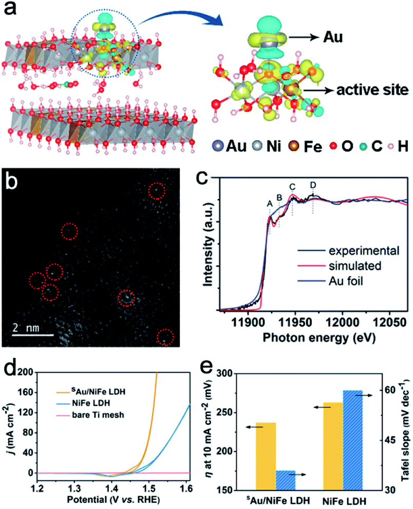 |
| | Fig. 3 (a) Differential charge densities of Ni–Fe LDH with and without Au atoms. (b) HAADF-STEM of sAu/Ni–Fe LDH. (c) Au L3-edge XANES spectra of sAu/Ni–Fe LDH and Au foil. (d) Polarization curves of sAu/Ni–Fe LDH, pure Ni–Fe LDH and Ti mesh. (e) η at 10 mA cm−2 and Tafel slope for sAu/Ni–Fe LDH and Ni–Fe LDH. Reproduced with permission.50 Copyright 2018, American Chemical Society. | |
Construction of electrochemical heterogeneous interfaces can expose more active sites and produce a more favorable interface to improve catalytic activity.52,53 For such a periodic structure, each unilamellar nanosheet simultaneously acts as both the active component and the interface to maximize the synergistic effect between different layers. Besides, each stacked nanosheet could serve as pillar to support each other for better structural stability. Therefore, long service life of the electrocatalysts could be expected. For example, Xiong et al. studied the interface between MoS2 and Ni–Fe LDH unilamellar nanosheets through molecular-scale regulation of superlattices.54 MoS2 is considered to be a promising non-precious HER electrocatalyst in acidic media, which might improve the HER performance of Ni–Fe LDH. Meanwhile, graphene could enhance the conductivity. As shown in Fig. 4a, the group systematically designed three superlattices by alternate restacking of any two of MoS2, Ni–Fe LDH and graphene unilamellar nanosheets through a solution-phase assembly strategy. During the process, these two oppositely charged monolayers assembled into a layer-by-layer structure because of the electrostatic attraction. Owing to the various compositions, different superlattices show diverse activities towards water splitting. MoS2/LDH nanosheets could demonstrate a good response towards the HER and OER. However, MoS2/graphene and Ni–Fe LDH/graphene could only show HER activity and OER activity in alkaline solution, respectively. The TEM image shows that no agglomeration could be seen on the heterogeneous superlattice (Fig. 4b). Two broad peaks at small angles can be identified in the X-ray diffraction (XRD) pattern of MoS2/LDH nanosheets (Fig. 4c). The corresponding basic spacing is about 0.85–0.95 nm, which is almost half of the total thicknesses of MoS2 and LDH nanosheets. Furthermore, the HRTEM image shows a periodic layered structure with a spacing of 1.8 nm, verifying the formation of the layer-by-layer structure between MoS2 and LDH (Fig. 4d). The prepared MoS2/Ni–Fe LDH sandwich-like structure demonstrates superior HER and OER activity over MoS2/graphene and Ni–Fe LDH/graphene with a small η of 110 and 210 mV to deliver a current density of 10 mA cm−2, respectively. This enhanced electrocatalytic performance should be attributed to structural advantages from the molecular-scale modulation. Moreover, the charge transfer from LDH to MoS2 realizes a strong coupling effect at the interfaces for the fastest electron transfer among samples. The energy profiles of vital intermediates (*OH, *O, and *OOH) for the four-step OER on these layer-by-layer structures are estimated (Fig. 4e). The conversion from *O to *OOH is considered to be the potential determining step (pds). MoS2/LDH bilayer structures show a ΔGpds of 1.8 eV, which is much better compared with that of LDH (∼7.8 eV) and LDH/graphene (2.2 eV). For the HER in KOH, the MoS2/LDH sample also demonstrated compositional superiority with the highest H+ affinity with the smallest ΔGH* of 0.10 eV (Fig. 4f). This successful molecular-scale modulation between Ni–Fe LDH and other nanosheets synergistically accelerates the overall water splitting reactions, shedding light on the further electrocatalyst designs.
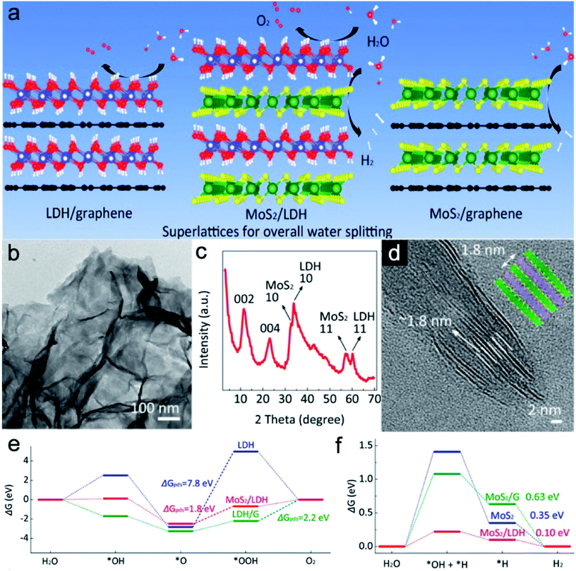 |
| | Fig. 4 (a) Schematic diagram of MoS2/LDH and control samples for different processes in water splitting. (b) TEM image, (c) XRD pattern, and (d) HRTEM image of the MoS2/LDH sample. Free energy illustrations of (e) the OER and (f) HER on MoS2/LDH and control samples. Reproduced with permission.54 Copyright 2019, American Chemical Society. | |
4. Other Ni–Fe based compounds
With the continuous development of Ni–Fe LDH, researchers begin to explore other Ni–Fe based compounds beyond LDH, such as alloys, sulfides, phosphides and so on. Due to strong affinity between Ni and Fe, these two elements could easily form Ni–Fe alloys with good electrical conductivity.24 However, Ni–Fe alloys face great challenges as they cannot retain the original phase or morphology during long-time utilization in alkaline/acid solutions or under high potential.31 In addition, nanosized alloys are prone to agglomerate during synthesis. Usually, carbon materials could serve not only as a substrate to load the alloys or coating layer to prevent alloys from agglomeration, but also as conductive additives with excellent stability in harsh environments to improve the catalytic activity. As for the Ni–Fe chalcogenides (sulfides, selenides, etc.)/oxyphosphides/phosphides, their electrical conductivity is much better compared with LDHs, which is favorable for the electrocatalytic water splitting. Nevertheless, the surface of these ternary compounds could turn into oxyhydroxides as the actual active sites during the cycling.32 Therefore, it is quite difficult to identify the origin of the enhanced electrocatalytic performances and deeper investigations are still needed to further optimize these Ni–Fe based compounds as electrocatalysts in water splitting.
4.1. Ni–Fe alloys
To address the synthetic obstacles, mechanical alloying or electrolytic deposition of mixed metal salt solution is employed.24 Although many unique studies have been done, phase modulation of Ni–Fe alloys is seldom reported and many reported these alloys as face-centered cubic (fcc) phases. The crystal structure of alloys mainly contains three forms other than the fcc phase: body-centered cubic (bcc), hexagonal close-packed (hcp) and face-centered tetragonal (fct) structures. Wang and coworkers have developed a rare crystal structure that encapsulates hcp-phase Ni–Fe alloy nanoparticles in an N-doped carbon (NC) shell (hcp-Ni–Fe@NC).55 XRD shows that all diffraction peaks correspond to the hcp structure of Ni–Fe alloys (Fig. 5a). SEM and TEM images clearly show that the Ni–Fe alloys are sphere-like nanostructures with a uniform size of 50 nm with a thin carbon layer (Fig. 5b and c). The inset HRTEM image with a clear d-spacing of 0.232 nm further confirms the hcp-phase of Ni–Fe alloys. The polarization curves in Fig. 5d show that hcp-Ni–Fe@NC has excellent OER catalytic activity among Ni–Fe alloys with different phases. The hcp-Ni–Fe@NC sample only requires a small η of 226 mV to deliver a current of 10 mA cm−2, much smaller than that of the fcc-Ni–Fe@NC (292 mV) and RuO2 (344 mV). The Tafel slope of hcp-Ni–Fe@NC is 41 mV dec−1, which also confirms the superiority over fcc-Ni–Fe@NC and RuO2 (Fig. 5e). The long-term cycling test reveals the excellent high stability of hcp-Ni–Fe@NC with only a slight performance decay after 35 h. For comparison, RuO2 can only maintain 68.3% of the original performance (Fig. 6f). This crystal phase regulation changes the accumulation of metal atoms to affect electronic properties, which greatly alters the intrinsic catalytic performance of Ni–Fe alloys. In addition, hcp-Ni–Fe@NC samples with different Fe/Ni ratios are also prepared. Once again, hcp-Ni–Fe@NC proves its compositional advantages as its OER activity is much better than that of hcp-Ni–Fe@NC-1 and hcp-Ni–Fe@NC-2 (Fig. 5g). When the η is 250 mV, hcp-Ni–Fe@NC gives the highest current density of 36.6 mA cm−2 (Fig. 5h). EIS data at a constant potential of 1.5 V (vs. the reversible hydrogen electrode, RHE) show that hcp-Ni–Fe@NC has the lowest Rct value compared with other control samples, verifying its excellent OER performances (Fig. 5i).
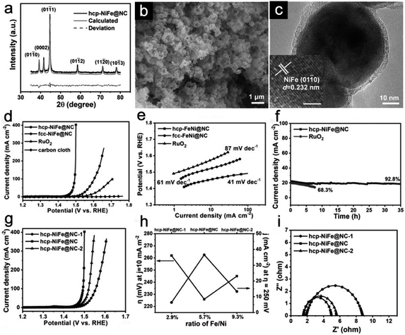 |
| | Fig. 5 (a) XRD patterns, (b) SEM image, and (c) TEM image of hcp-NiFe@NC, (d) LSV curves and (e) Tafel plots of catalysts with different phases. (f) I–t curves of the hcp-Ni–Fe@NC and RuO2. (g) LSV curves of NiFe alloys with different Fe/Ni ratios. (h) OER performances of NiFe alloy samples at the current density of 10 mA cm−2 and the η of 250 mV. (i) Nyquist plots of NiFe alloy samples. Reproduced with permission.55 Copyright 2019, John Wiley & Sons, Inc. | |
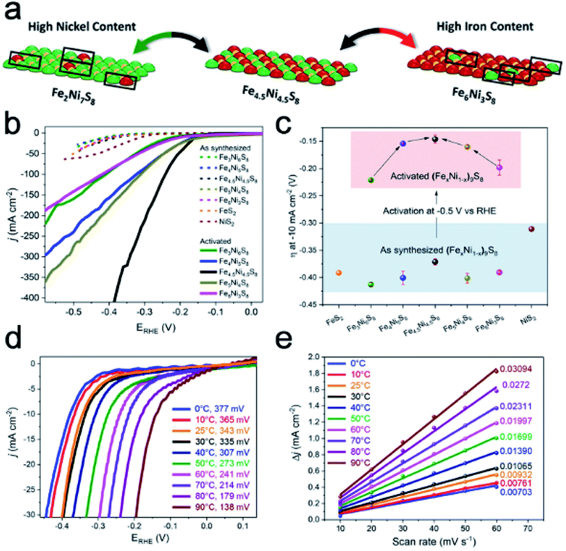 |
| | Fig. 6 (a) Schematic surface area of (FexNi1−x)9S8 with different Ni/Fe ratios. (b) LSV curves and (c) η for synthesized and activated (FexNi1−x)9S8 samples. (d) LSV curves of Fe4.5Ni4.5S8 at different temperatures. (e) Charging current density differences (ΔJ = ja − jc) plotted. Reproduced with permission.58 Copyright 2018, American Chemical Society. | |
4.2. Ni–Fe based sulfides
Ni–Fe sulfides are a typical kind of Ni–Fe chalcogenides with low cost, high conductivity and robust features, and are generally regarded as active electrocatalysts for the HER.56 DFT calculations indicate that specific Ni–Fe interactions with different Ni/Fe ratios have a significant effect on the binding of hydrogen to the catalyst surface.57 As a typical example, Piontek et al. synthesized a series of (FexNi1−x)9S8 (x = 0–1) materials through high-temperature annealing and analyzed the effects of the Ni/Fe ratio and temperature of testing on the HER performance.58 Different Ni/Fe ratios will alter the distribution of Ni–Fe active sites on the surface. As shown in Fig. 6a, when the Ni/Fe ratio is close to 1, the whole catalyst approaches an idealized system with an ordered distribution of active sites, although the HER performances of the freshly made catalysts with different Ni/Fe ratios are almost the same (Fig. 6b). Activation treatment at a constant potential of −0.5 V vs. RHE for 20 h could vary their HER activities (Fig. 6c). Among them, Fe4.5Ni4.5S8 shows the smallest η of 146 mV, and all materials have a significant shift to more positive values. Meanwhile, samples with high or low Ni/Fe ratios suffer great loss in the long-term cycling performance. The above results indicate the changes of the chemical environment on the surface and potential surface corrosion of Ni–Fe based sulfides in acid. Interestingly, this work also investigates the effect of temperature on the HER test. LSV curves reveal that the increase in temperature will greatly enhance the OER performance to reduce the η and increase the reaction kinetics (Fig. 6d). It is believed that the increase of the operating temperature not only promotes the removal of H2 bubbles, but also reduces the charge transfer resistance. At the same time, as the temperature increases, the double-layer capacity/electrochemical surface area also increases, indicating a significant promotion of HER activity (Fig. 6e). It should be noted that the temperature could not change the internal HER reaction mechanisms.
4.3. Ni–Fe based phosphides
Transition metal phosphides (TMPs) have been considered to be attractive HER catalysts due to low cost, nontoxicity, and high activity in electrolytes with a wide range of pH values.59,60 However, amorphous oxyphosphides or oxyphosphides with a low degree of crystallinity are usually obtained. Therefore, it is hard to identify the active sites of Ni–Fe phosphides. Recently, Lu et al. reported an effective method to generate Ni-doped FeP/carbon (NFP/C) hollow nanorods with tailorable length and composition based on self-engaged etching and coordination reactions.61 Both the carbon and Ni-doped FeP species are derived from the phytic acid treated hollow MIL-88A (Fig. 7a). XRD patterns show the high crystallinity of NFP/C without any impurity (Fig. 7b). The TEM image reveals the rod-like morphology of these single-shelled hollow structures (Fig. 7c). EDX mapping results show that the carbon element is well dispersed within the whole particle (Fig. 7d). Carbon species could support Ni-doped FeP to avoid collapse during calcination. LSV plots (Fig. 7e) and Tafel plots (Fig. 7f) clearly show the superiority of NFP/C compared with pure iron phosphides. More importantly, the carbon content plays a great role in maintaining the structural integrity and catalytic performance in acidic, neutral, and alkaline solutions (Fig. 7g).
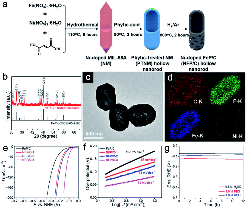 |
| | Fig. 7 (a) Schematic illustration of the formation of NFP/C hollow nanorods. (b) XRD pattern, (c) TEM image and (d) EDX mapping images of NFP/C hollow nanorods. (e) LSV plots and (f) Tafel plots of NFP/C hollow nanorods with different Ni/Fe ratios in acid. (g) Durability test of NFP/C in acidic, neutral, and alkaline solutions. Reproduced with permission.61 Copyright 2019, The American Association for the Advancement of Science. | |
5. Conclusion and outlook
Scientists have made great efforts to design novel and highly efficient electrocatalytic materials to promote water splitting reactions. As an advanced approach for enhancing the production of hydrogen and oxygen, the employment of Ni–Fe based compounds has aroused great interest due to the abundant reserves and low prices, and a strong synergistic effect between Fe and Ni elements. This review sums up the recent progress in the design of Ni–Fe based electrocatalysts, including Ni–Fe LDH and other compounds for the OER (Table 1) and the HER (Table 2). Special focus has been put on the utilization of hollow structures, interface engineering, phase control and carbon coating toward Ni–Fe LDH and beyond.
Table 1 Electrocatalytic performances of Ni–Fe based compounds for the OER
| Electrocatalyst |
η at 10 mA cm−2 (mV) |
Tafel slope (mV dec−1) |
Electrolyte |
Ref. |
| Cu@NiFe LDH |
199 |
27.8 |
1 M KOH |
4
|
| NiO/NiFe LDH |
180 |
30 |
1 M KOH |
10
|
| NiFeLDH@defective graphene |
300 |
52 |
1 M KOH |
12
|
| NiFe-LDH/Co,N-carbon |
312 |
60 |
0.1 M KOH |
26
|
| Ni–Fe LDH |
280 |
49.4 |
1 M KOH |
46
|
| NiFe-LDH/carbon nanotube |
220 |
31 |
1 M KOH |
49
|
|
sAu/NiFe LDH |
237 |
55 |
1 M KOH |
50
|
| MoS2/NiFe-LDH |
210 |
46 |
1 M KOH |
54
|
| FeNi@graphene |
280 |
70 |
1 M NaOH |
31
|
| NiFe nanoparticle@N-doped carbon |
226 |
41 |
1 M KOH |
55
|
| Tannic acid–Ni3Fe |
290 |
28 |
1 M KOH |
60
|
| NH2-MIL-88B(Fe2Ni)/Ni foam |
240 |
58.5 |
1 M KOH |
3
|
| Fe–Ni@dicyandiamide composite-carbon nanotubes |
274 |
45.74 |
1 M KOH |
6
|
| Ni0.8Fe0.2(C12H6O4)(H2O)4 |
240 |
34 |
0.1 M KOH |
27
|
| NiFe–Prussian blue analogue |
258 |
46 |
1 M KOH |
28
|
| Fe(Ni)-MOF/NiFe alloy foam |
227 |
38.9 |
1 M KOH |
41
|
| MIL-100(FeNi)/Ni foam |
243 |
30.4 |
1 M KOH |
57
|
Table 2 Electrocatalytic performances of Ni–Fe based compounds for the HER
| Electrocatalyst |
η at 10 mA cm−2 (mV) |
Tafel slope (mV dec−1) |
Electrolyte |
Ref. |
| NiFeRu-LDH |
29 |
31 |
1 M KOH |
2
|
| Cu@NiFe LDH |
116 |
58.9 |
1 M KOH |
4
|
| Rh/NiFeRh-LDH |
57 |
81.3 |
1 M KOH |
9
|
| MoS2/NiFe-LDH |
110 |
77 |
1 M KOH |
54
|
| Fe4.5Ni4.5S8 |
138 |
83 |
0.5 M H2SO4 |
58
|
| Ni-doped FeP/C |
72 |
54 |
1 M KOH |
61
|
| NH2-MIL-88B(Fe2Ni)/Ni foam |
87 |
35.2 |
1 M KOH |
3
|
| Ni0.9Fe0.1PS3 |
72 |
73 |
1 M KOH |
59
|
Despite advances, there are still several urgent bottlenecks to be addressed in the research of Ni–Fe based compounds for electrochemical water splitting. Above all, the electrocatalytic performances of current Ni–Fe based compounds are still inferior to that of precious metal based electrocatalysts, which could not meet the demand for practical water splitting at low energy consumption. In addition, the preparation routes for Ni–Fe based compounds are still quite complex and the yield should be further improved for large-scale applications. Moreover, the origin of Ni–Fe based compounds beyond Ni–Fe LDH is still not clear due to the complex composition and phases. In situ analyses during the actual process are required to monitor the changes in the phase, morphology, and valence evolution of the catalysts. Besides, highly effective electrocatalysts based on Ni–Fe compounds are still needed for overall water splitting in wide pH ranges. For further research, more attention should be paid to the surface and interface modulation strategies towards Ni–Fe based compounds. A deeper understanding of the active sites or species should be obtained. More facile and price-competitive preparation methods for Ni–Fe based compounds should be developed for commercial use.
Conflicts of interest
There are no conflicts to declare.
Acknowledgements
L. Y. acknowledges the National Natural Science Foundation of China (Grant No. 51902016), the financial support from Fundamental Research Funds for the Central Universities (Grant No. buctrc201829). N. W. L. acknowledges the financial support from Fundamental Research Funds for the Central Universities (Grant No. buctrc201904).
Notes and references
- D. Gielen, F. Boshell and D. Saygin, Nat. Mater., 2016, 15, 117–120 CrossRef CAS.
- G. B. Chen, T. Wang, J. Zhang, P. Liu, H. J. Sun, X. D. Zhuang, M. W. Chen and X. L. Feng, Adv. Mater., 2018, 30, 1706279 CrossRef.
- D. Senthil Raja, X. F. Chuah and S. Y. Lu, Adv. Energy Mater., 2018, 8, 1801065 CrossRef.
- L. Yu, H. Q. Zhou, J. Y. Sun, F. Qin, F. Yu, J. M. Bao, Y. Yu, S. Chen and Z. F. Ren, Energy Environ. Sci., 2017, 10, 1820–1827 RSC.
- Y. Wang, B. Kong, D. Y. Zhao, H. T. Wang and C. Selomulya, Nano Today, 2017, 15, 26–55 CrossRef CAS.
- X. J. Zhao, P. Pachfule, S. Li, J. R. J. Simke, J. Schmidt and A. Thomas, Angew. Chem., Int. Ed., 2018, 57, 8921–8926 CrossRef CAS.
- W. Hua, H. H. Sun, F. Xu and J. G. Wang, Rare Met., 2020, 39, 335–351 CrossRef CAS.
- C. G. Hu and L. M. Dai, Adv. Energy Mater., 2017, 29, 1604942 Search PubMed.
- B. W. Zhang, C. Q. Zhu, Z. S. Wu, E. Stavitski, Y. H. Lui, T. H. Kim, H. Liu, L. Huang, X. C. Luan, L. Zhou, K. Jiang, W. Y. Huang, S. Hu, H. L. Wang and J. S. Francisco, Nano Lett., 2020, 20, 136–144 CrossRef CAS.
- Z. W. Gao, J. Y. Liu, X. M. Chen, X. L. Zheng, J. Mao, H. Liu, T. Ma, L. Li, W. C. Wang and X. W. Du, Adv. Mater., 2019, 31, e1804769 CrossRef.
- T. Z. Tian, N. W. Li and L. Yu, CIESC J., 2020, 71, 2466–2480 Search PubMed.
- Y. Jia, L. Z. Zhang, G. P. Gao, H. Chen, B. Wang, J. Z. Zhou, M. T. Soo, M. Hong, X. C. Yan, G. R. Qian, J. Zou, A. J. Du and X. D. Yao, Adv. Mater., 2017, 29, 1700017 CrossRef.
- H. Gao, H. H. Yue, F. Qi, B. Yu, W. L. Zhang and Y. F. Chen, Rare Met., 2018, 37, 1014–1020 CrossRef CAS.
- S. Sultan, J. N. Tiwari, A. N. Singh, S. Zhumagali, M. Ha, C. W. Myung, P. Thangavel and K. S. Kim, Adv. Energy Mater., 2019, 9, 1900624 CrossRef.
- Z. W. Seh, J. Kibsgaard, C. F. Dickens, I. Chorkendorff, J. K. Nørskov and T. F. Jaramillo, Science, 2017, 355, eaad4998 CrossRef.
- V. Vij, S. Sultan, A. M. Harzandi, A. Meena, J. N. Tiwari, W. G. Lee, T. Yoon and K. S. Kim, ACS Catal., 2017, 7, 7196–7225 CrossRef CAS.
- W. R. Cheng, X. Zhao, H. Su, F. m. Tang, W. Che, H. Zhang and Q. H. Liu, Nat. Energy, 2019, 4, 115–122 CrossRef CAS.
- K. Wu, Acta Phys.-Chim. Sin., 2020, 36, 1910033 Search PubMed.
- Z. C. Zhang and H. Zhang, Acta Phys.-Chim. Sin., 2017, 33, 1923–1924 CAS.
- S. M. Yin, W. G. Tu, Y. Sheng, Y. H. Du, M. Kraft, A. Borgna and R. Xu, Adv. Mater., 2018, 30, 1705106 CrossRef.
- F. Dionigi and P. Strasser, Adv. Energy Mater., 2016, 6, 1600621 CrossRef.
- Z. Y. Zhang, S. S. Liu, F. Xiao and S. Wang, ACS Sustainable Chem. Eng., 2017, 5, 529–536 CrossRef CAS.
- Z. Y. Zhang, S. S. Liu, J. Xiao and S. Wang, J. Mater. Chem. A, 2016, 4, 9691–9699 RSC.
- M. Gong and H. J. Dai, Nano Res., 2015, 8, 23–39 CrossRef CAS.
- J. T. Li, W. Z. Huang, M. M. Wang, S. B. Xi, J. S. Meng, K. N. Zhao, J. Jin, W. W. Xu, Z. Y. Wang, X. Liu, Q. Chen, L. H. Xu, X. B. Liao, Y. L. Jiang, K. A. Owusu, B. L. Jiang, C. X. Chen, D. N. Fan, L. Zhou and L. Q. Mai, ACS Energy Lett., 2018, 4, 285–292 CrossRef.
- Q. Wang, L. Shang, R. Shi, X. Zhang, Y. F. Zhao, G. I. N. Waterhouse, L. Z. Wu, C. H. Tung and T. R. Zhang, Adv. Energy Mater., 2017, 7, 1700467 CrossRef.
- J. J. Duan, S. Chen and C. Zhao, Nat. Commun., 2017, 8, 15341 CrossRef CAS.
- X. Z. Su, Y. Wang, J. Zhou, S. Q. Gu, J. Li and S. Zhang, J. Am. Chem. Soc., 2018, 140, 11286–11292 CrossRef CAS.
- F. Z. Sun, G. Wang, Y. Q. Ding, C. Wang, B. B. Yuan and Y. Q. Lin, Adv. Energy Mater., 2018, 8, 1800584 CrossRef.
- V. R. Stamenkovic, D. Strmcnik, P. P. Lopes and N. M. Markovic, Nat. Mater., 2017, 16, 57–69 CrossRef CAS.
- X. J. Cui, P. J. Ren, D. H. Deng, J. Deng and X. H. Bao, Energy Environ. Sci., 2016, 9, 123–129 RSC.
- K. Fan, H. Y. Zou, Y. Lu, H. Chen, F. S. Li, J. X. Liu, L. C. Sun, L. P. Tong, M. F. Toney, M. L. Sui and J. G. Yu, ACS Nano, 2018, 12, 12369–12379 CrossRef CAS.
- F. Song, L. C. Bai, A. Moysiadou, S. Lee, C. Hu, L. Liardet and X. L. Hu, J. Am. Chem. Soc., 2018, 140, 7748–7759 CrossRef CAS.
- J. T. Zhang, L. Yu, Y. Chen, X. F. Lu, S. Y. Gao and X. W. Lou, Adv. Mater., 2020, 32, 1906432 CrossRef CAS.
- Y. Chen, Z. C. Lai, X. Zhang, Z. X. Fan, Q. Y. He, C. L. Tan and H. Zhang, Nat. Rev. Chem., 2020, 4, 243–256 CrossRef CAS.
- B. You, M. T. Tang, C. Tsai, F. Abild-Pedersen, X. L. Zheng and H. Li, Adv. Mater., 2019, 31, 1807001 CrossRef.
- X. J. Fan, Y. Y. Liu, S. Chen, J. J. Shi, J. J. Wang, A. L. Fan, W. Y. Zan, S. D. Li, W. A. Goddard III and X. M. Zhang, Nat. Commun., 2018, 9, 1809 CrossRef.
- J. S. Kim, B. Kim, H. Kim and K. Kang, Adv. Energy Mater., 2018, 8, 1702774 CrossRef.
- Z. Cai, D. J. Zhou, M. Y. Wang, S. M. Bak, Y. S. Wu, Z. S. Wu, Y. Tian, X. Y. Xiong, Y. P. Li, W. Liu, S. Siahrostami, Y. Kuang, X. Q. Yang, H. Duan, Z. X. Feng, H. L. Wang and X. M. Sun, Angew. Chem., Int. Ed., 2018, 57, 9392–9396 CrossRef CAS.
- P. S. Li, X. X. Duan, Y. Kuang, Y. P. Li, G. X. Zhang, W. Liu and X. M. Sun, Adv. Energy Mater., 2018, 8, 1703341 CrossRef.
- C. S. Cao, D. D. Ma, Q. Xu, X. T. Wu and Q. L. Zhu, Adv. Funct. Mater., 2018, 29, 1807418 CrossRef.
- Y. M. Bi, Z. Cai, D. J. Zhou, Y. Tian, Q. Zhang, Q. Zhang, Y. Kuang, Y. P. Li, X. M. Sun and X. Duan, J. Catal., 2018, 358, 100–107 CrossRef CAS.
- L. Yu, X. Y. Yu and X. W. Lou, Adv. Mater., 2018, 30, 1800939 CrossRef.
- L. Yu, H. Hu, H. B. Wu and X. W. Lou, Adv. Mater., 2017, 29, 1604563 CrossRef.
- G. Prieto, H. Tüysüz, N. Duyckaerts, J. Knossalla, G.-H. Wang and F. Schüth, Chem. Rev., 2016, 116, 14056–14119 CrossRef CAS.
- L. Yu, J. F. Yang, B. Y. Guan, Y. Lu and X. W. Lou, Angew. Chem., Int. Ed., 2018, 57, 172–176 CrossRef CAS.
- B. W. Li and H. C. Zeng, Adv. Mater., 2019, 31, 1801104 CrossRef.
- G. Zhan, P. Li and H. C. Zeng, Adv. Mater., 2018, 30, e1802094 CrossRef.
- M. Gong, Y. G. Li, H. L. Wang, Y. Y. Liang, J. Z. Wu, J. G. Zhou, J. Wang, T. Regier, F. Wei and H. J. Dai, J. Am. Chem. Soc., 2013, 135, 8452–8455 CrossRef CAS.
- J. Zhang, J. Liu, L. Xi, Y. Yu, N. Chen, S. Sun, W. Wang, K. M. Lange and B. Zhang, J. Am. Chem. Soc., 2018, 140, 3876–3879 CrossRef CAS.
- S. J. Gutić, A. S. Dobrota, E. Fako, N. V. Skorodumova, N. López and I. A. Pašti, Catalysts, 2020, 10, 290 CrossRef.
- H. J. Yan, Y. Xie, A. P. Wu, Z. C. Cai, L. Wang, C. G. Tian, X. M. Zhang and H. G. Fu, Adv. Mater., 2019, 31, 1901174 CrossRef.
- H. J. Xu, J. Cao, C. F. Shan, B. K. Wang, P. X. Xi, W. S. Liu and Y. Tang, Angew. Chem., Int. Ed., 2018, 57, 8654–8658 CrossRef CAS.
- P. Xiong, X. Y. Zhang, H. Wan, S. J. Wang, Y. F. Zhao, J. Q. Zhang, D. Zhou, W. C. Gao, R. Z. Ma, T. Sasaki and G. X. Wang, Nano Lett., 2019, 19, 4518–4526 CrossRef CAS.
- C. H. Wang, H. C. Yang, Y. J. Zhang and Q. B. Wang, Angew. Chem., Int. Ed., 2019, 58, 6099–6103 CrossRef CAS.
- C. L. Bentley, C. Andronescu, M. Smialkowski, M. Kang, T. Tarnev, B. Marler, P. R. Unwin, U. P. Apfel and W. Schuhmann, Angew. Chem., Int. Ed., 2018, 57, 4093–4097 CrossRef CAS.
- C. Q. Li, Y. W. Liu, G. Wang, L. H. Guan and Y. Q. Lin, ACS Sustainable Chem. Eng., 2019, 7, 7496–7501 CrossRef CAS.
- S. Piontek, C. Andronescu, A. Zaichenko, B. Konkena, K. junge Puring, B. Marler, H. Antoni, I. Sinev, M. Muhler, D. Mollenhauer, B. Roldan Cuenya, W. Schuhmann and U. P. Apfel, ACS Catal., 2018, 8, 987–996 CrossRef CAS.
- B. Song, K. Li, Y. Yin, T. Wu, L. N. Dang, M. Cabán-Acevedo, J. C. Han, T. L. Gao, X. J. Wang, Z. H. Zhang, J. R. Schmidt, P. Xu and S. Jin, ACS Catal., 2017, 7, 8549–8557 CrossRef CAS.
- Y. M. Shi, Y. Yu, Y. Liang, Y. H. Du and B. Zhang, Angew. Chem., Int. Ed., 2019, 58, 3769–3773 CrossRef CAS.
- X. F. Lu, L. Yu and X. W. Lou, Sci. Adv., 2019, 5, eaav6009 CrossRef CAS.
|
| This journal is © The Royal Society of Chemistry 2020 |
Click here to see how this site uses Cookies. View our privacy policy here.  Open Access Article
 *
*


