 Open Access Article
Creative Commons Attribution 3.0 Unported Licence
Investigations into the superionic glass phase of Li4PS4I for improving the stability of high-loading all-solid-state batteries†
Florian
Strauss
*a,
Jun Hao
Teo
a,
Jürgen
Janek
 ab and
Torsten
Brezesinski
 *a
*a
aBattery and Electrochemistry Laboratory, Institute of Nanotechnology, Karlsruhe Institute of Technology (KIT), Hermann-von-Helmholtz-Platz 1, 76344 Eggenstein-Leopoldshafen, Germany. E-mail: florian.strauss@kit.edu; torsten.brezesinski@kit.edu
bInstitute of Physical Chemistry & Center for Materials Science, Justus-Liebig-University Giessen, Heinrich-Buff-Ring 17, 35392 Giessen, Germany
First published on 17th August 2020
Abstract
In recent years, investigations into improving the performance of bulk-type solid-state batteries (SSBs) have attracted much attention. This is due, in part, to the fact that they offer an opportunity to outperform the present Li-ion battery technology in terms of energy density. Ni-rich Li1+x(Ni1−y−zCoyMnz)1−xO2 (NCM) and lithium-thiophosphate-based solid electrolytes appear to be a promising material combination for application at the cathode side. Here, we report about exploratory investigations into the 1.5Li2S/0.5P2S5/LiI phase system and demonstrate that a glassy solid electrolyte has more than an order of magnitude higher room-temperature ionic conductivity than the crystalline counterpart, tetragonal Li4PS4I with the P4/nmm space group (∼1.3 versus ∼0.2 mS cm−1). In addition, preliminary results show that usage of the glassy 1.5Li2S–0.5P2S5–LiI in pellet stack SSB cells with an NCM622 (60% Ni content) cathode and a Li4Ti5O12 anode leads to enhanced capacity retention when compared to the frequently employed argyrodite Li6PS5Cl solid electrolyte. This indicates that, apart from interfacial instabilities, the stiffness (modulus) of the solid electrolyte and associated mechanical effects may also impact significantly the long-term performance. Moreover, SSB cells with the glassy 1.5Li2S–0.5P2S5–LiI and high-loading cathode (∼22 mgNCM622 cm−2) manufactured using a slurry-casting process are found to cycle stably for 200 cycles at C/5 rate and 45 °C, with areal capacities in excess of 3 mA h cm−2.
Introduction
Solid-state batteries (SSBs) are currently under intense investigation, primarily because of their prospect of delivering higher energy and power densities than state-of-the-art liquid-electrolyte-based Li-ion batteries.1,2 Recent work on combining layered lithium metal oxide cathode active materials (CAMs) with lithium thiophosphate solid electrolytes has shown promising results regarding cell capacity and capacity retention.3–7 This is due, in part, to the high ionic conductivity of both amorphous and crystalline thiophosphate-based solid electrolytes and their comparably low rigidity, allowing intimate physical contact with the CAM secondary particles.8–10 The latter is of particular importance when using Ni-rich materials, such as Li1+x(Ni1−y−zCoyMnz)1−xO2 (NCM) with ≥60% Ni content, as they undergo large volumetric changes upon (de)lithiation.6,11–16 In general, volume change effects can be mitigated by introducing zero- or low-strain CAMs (at the expense of specific capacity though)15,17 or somewhat accommodated by the solid electrolyte itself, with mechanically relatively soft lithium thiophosphates being the materials of choice at present.In the quest for new, superionic solid electrolytes, a tetragonal Li4PS4I with P4/nmm space group synthesized by a solution-based method has been reported recently and shown to exhibit room-temperature Li-ion conductivities in the range of 6.4 × 10⁻⁵ to 1.2 × 10⁻⁴ S cm−1, with activation energies for conduction of 0.37 to 0.43 eV.18 Moreover, density functional theory (DFT) calculations pointed towards an exceptionally high ionic conductivity around 10−1 S cm−1.19 Taken together, these reports and especially the prospects of achieving high ionic conductivity in the xLi2S/yP2S5/zLiI system (amorphous, crystalline or both)18–24 motivated us to embark on an investigation into the preparation of the glass (ceramic) phase of Li4PS4I.
Specifically, we present a comparative study following the changes in the ionic conductivity and crystal structure during mechanochemical synthesis (ball-milling-assisted amorphization of a precursor mixture stoichiometrically equivalent to 1.5Li2S–0.5P2S5–LiI or Li4PS4I) and post annealing at 155–250 °C. The results indicate that, in agreement with the literature on analogous solid electrolytes, the glass phase possesses the highest ionic conductivity and small amounts of crystalline side products or impurities have a relatively strong negative effect on the transport properties (ion dynamics). Moreover, 1.5Li2S–0.5P2S5–LiI-based SSBs with an LiNbO3-coated NCM622 (60% Ni) cathode and a Li4Ti5O12 (LTO) anode are shown to outperform (in terms of long-term cycling performance) identical cells with an argyrodite Li6PS5Cl solid electrolyte and to cycle stably even when using a high-loading, slurry-cast cathode.
Experimental
Materials and synthesis
For the synthesis of the 1.5Li2S–0.5P2S5–LiI solid electrolyte, 1.5 g of stoichiometric amounts of Li2S (Sigma-Aldrich; 99.9%), P2S5 (Sigma-Aldrich; 99%) and LiI (99.99%; Alfa Aesar) were mixed in a planetary ball-mill (Fritsch) under an argon atmosphere for up to 12 h at 450 rpm using a 70 mL zirconia jar loaded with twenty 10 mm diameter zirconia balls. For subsequent heat-treatment, 250 mg of powder were pressed under an argon atmosphere into 10 mm diameter pellets. The pellets were then vacuum-sealed (1.0 × 10⁻³ mbar) in quartz ampoules and annealed in a box furnace (Nabertherm) for 12 h at temperatures up to 250 °C. The heating rate was 5 °C min−1. The quartz ampoules were dried under dynamic vacuum for 15 min at 650 °C prior to usage.For the synthesis of the Li6PS5Cl solid electrolyte, 5 g of a mixture of Li2S (10 mol% deficiency), P2S5 and LiCl (99+%; Alfa Aesar) was milled under an argon atmosphere, first for 1 h at 250 rpm and then for 20 h at 450 rpm using a 250 mL zirconia jar containing 10 mm diameter zirconia balls with a 30![[thin space (1/6-em)]](https://www.rsc.org/images/entities/char_2009.gif) :
:![[thin space (1/6-em)]](https://www.rsc.org/images/entities/char_2009.gif) 1 ball-to-powder ratio. LiCl was dried in a vacuum for 12 h at 300 °C prior to usage. After milling, the powder was heated in a vacuum for 5 h at 300 °C. The room-temperature ionic conductivity of the resulting Li6PS5Cl solid electrolyte was ∼2.0 mS cm−1 (∼7.4 mS cm−1 at 45 °C).
1 ball-to-powder ratio. LiCl was dried in a vacuum for 12 h at 300 °C prior to usage. After milling, the powder was heated in a vacuum for 5 h at 300 °C. The room-temperature ionic conductivity of the resulting Li6PS5Cl solid electrolyte was ∼2.0 mS cm−1 (∼7.4 mS cm−1 at 45 °C).
Small-sized NCM622 with d50 = 2.9 μm and d90 = 6.0 μm was received from BASF SE.25 A 1 wt% LiNbO3 coating was applied to the CAM particles prior to usage.4,26
Characterization
The phase composition was studied by powder X-ray diffraction (PXRD) in borosilicate glass capillaries (Hilgenberg) with an inner diameter of 0.48 mm and a wall thickness of 0.01 mm using a STADI P diffractometer (STOE) equipped with a Cu-Kα1 radiation source.Rietveld analysis was performed using FullProf software. The Thompson-Cox-Hastings pseudo-Voigt function was used as a profile function and the scale factor, background coefficients (Chebyshev function with 24 parameters), reflection shape parameters, lattice parameters, atomic coordinates (for Li4PS4I) and zero-shift were refined. Isotropic displacement factors were fixed in the refinement analysis to avoid divergence.18
Electrochemical impedance spectroscopy (EIS) was performed on an SP-200 potentiostat (BioLogic). For the conductivity measurements, 150 mg of solid electrolyte powder were compressed at 440 MPa in a custom-built setup. A constant pressure of 250 MPa was maintained during the experiment. Impedance spectra were collected in the range of 100 mHz to 7.0 MHz with an AC voltage amplitude of 10 mV. The experimental data were fitted with EC-Lab software (BioLogic) using (R1Q1)Q2 and (R1Q1)(R2Q2)(R3Q3)Q4 equivalent circuits for the solid electrolyte conductivity and SSB measurements, respectively.
Differential scanning calorimetry (DSC) was conducted under an argon atmosphere on samples sealed in aluminum crucibles using a NETZSCH DSC 204 F1 Phoenix. The heating rate was 5 °C min−1.
Scanning electron microscopy (SEM) imaging was performed using a LEO-1530 microscope (Carl Zeiss AG) equipped with a field emission source at 10 kV. Samples for cross-sectional SEM were prepared by breaking them in half.
Electrode preparation and cell testing
The cathode composite for binder-free SSB cells was prepared by mixing NCM622 CAM with 1.5Li2S–0.5P2S5–LiI or Li6PS5Cl solid electrolyte (7![[thin space (1/6-em)]](https://www.rsc.org/images/entities/char_2009.gif) :
:![[thin space (1/6-em)]](https://www.rsc.org/images/entities/char_2009.gif) 3 weight ratio) and 1 wt% Super C65 carbon black (Timcal) in a planetary ball-mill under an argon atmosphere for 30 min at 140 rpm using 10 mm diameter zirconia balls.27 The anode composite was prepared by mixing carbon-coated LTO (NEI Corp.), Super C65 carbon black and solid electrolyte in a 3
3 weight ratio) and 1 wt% Super C65 carbon black (Timcal) in a planetary ball-mill under an argon atmosphere for 30 min at 140 rpm using 10 mm diameter zirconia balls.27 The anode composite was prepared by mixing carbon-coated LTO (NEI Corp.), Super C65 carbon black and solid electrolyte in a 3![[thin space (1/6-em)]](https://www.rsc.org/images/entities/char_2009.gif) :
:![[thin space (1/6-em)]](https://www.rsc.org/images/entities/char_2009.gif) 1
1![[thin space (1/6-em)]](https://www.rsc.org/images/entities/char_2009.gif) :
:![[thin space (1/6-em)]](https://www.rsc.org/images/entities/char_2009.gif) 6 weight ratio. Both LTO and Super C65 carbon black were dried in a vacuum for 12 h at 300 °C prior to usage.
6 weight ratio. Both LTO and Super C65 carbon black were dried in a vacuum for 12 h at 300 °C prior to usage.
A custom-built setup with two stainless steel dies and 10 mm diameter PEEK sleeve was used for the SSB cell assembly. 100 mg of solid electrolyte were compressed first at 125 MPa, followed by 11 mg of cathode composite and 65 mg of anode composite on each side. The pellet stack was then compressed at 440 MPa. Charge/discharge testing was performed at 55 MPa and at 45 °C and different rates from 1C to C/5 (1C = 180 mA gNCM622−1) in the voltage range between 1.35 and 2.85 V vs. Li4Ti5O12/Li7Ti5O12, equivalent to ∼2.9–4.4 V vs. Li+/Li, using a MACCOR battery cycler. All cells were kept at open-circuit voltage for 1 h prior to electrochemical cycling.
The cathode composite tape was prepared by mixing NCM622 CAM, 1.5Li2S–0.5P2S5–LiI solid electrolyte, Super C65 carbon black and polyisobutylene binder (Oppanol®; BASF SE)28 with a weight ratio of 2.9![[thin space (1/6-em)]](https://www.rsc.org/images/entities/char_2009.gif) :
:![[thin space (1/6-em)]](https://www.rsc.org/images/entities/char_2009.gif) 6.9
6.9![[thin space (1/6-em)]](https://www.rsc.org/images/entities/char_2009.gif) :
:![[thin space (1/6-em)]](https://www.rsc.org/images/entities/char_2009.gif) 0.1
0.1![[thin space (1/6-em)]](https://www.rsc.org/images/entities/char_2009.gif) :
:![[thin space (1/6-em)]](https://www.rsc.org/images/entities/char_2009.gif) 0.1. The preparation process involved a series of mixing steps. The first step was a dry mixing of the NCM622, 1.5Li2S–0.5P2S5–LiI and carbon black at 600 rpm for 2 min in a Thinky mixer. The resulting powder was then wetted dropwise with the solvent (o-xylene from Sigma-Aldrich; anhydrous, 97%). The amount of o-xylene added was calculated to achieve a solid content of ∼64 wt% in the final slurry. The second step was a wet mixing at 600 rpm for 2 min, after which the binder solution (4 wt% Oppanol® in o-xylene) was added. This mixture was mixed twice at 2000 rpm for 6 min. The slurry obtained was then coated onto an Al foil current collector using a mini tape casting coater from MTI. Finally, the film was dried at room temperature in a two-step drying process, firstly until no visible wet spots remained and finally in a vacuum. All chemicals and processing steps were handled in an argon environment. The same custom-built setup was used and the sequence of assembly was identical. The slurry-cast cathode was punched into a circular geometry (9 mm diameter) and placed on top of the compressed solid electrolyte. The cells were cycled under a stack pressure of 55 MPa and at C/5 rate and 45 °C in the same voltage range of 1.35–2.85 V vs. Li4Ti5O12/Li7Ti5O12.
0.1. The preparation process involved a series of mixing steps. The first step was a dry mixing of the NCM622, 1.5Li2S–0.5P2S5–LiI and carbon black at 600 rpm for 2 min in a Thinky mixer. The resulting powder was then wetted dropwise with the solvent (o-xylene from Sigma-Aldrich; anhydrous, 97%). The amount of o-xylene added was calculated to achieve a solid content of ∼64 wt% in the final slurry. The second step was a wet mixing at 600 rpm for 2 min, after which the binder solution (4 wt% Oppanol® in o-xylene) was added. This mixture was mixed twice at 2000 rpm for 6 min. The slurry obtained was then coated onto an Al foil current collector using a mini tape casting coater from MTI. Finally, the film was dried at room temperature in a two-step drying process, firstly until no visible wet spots remained and finally in a vacuum. All chemicals and processing steps were handled in an argon environment. The same custom-built setup was used and the sequence of assembly was identical. The slurry-cast cathode was punched into a circular geometry (9 mm diameter) and placed on top of the compressed solid electrolyte. The cells were cycled under a stack pressure of 55 MPa and at C/5 rate and 45 °C in the same voltage range of 1.35–2.85 V vs. Li4Ti5O12/Li7Ti5O12.
Results and discussion
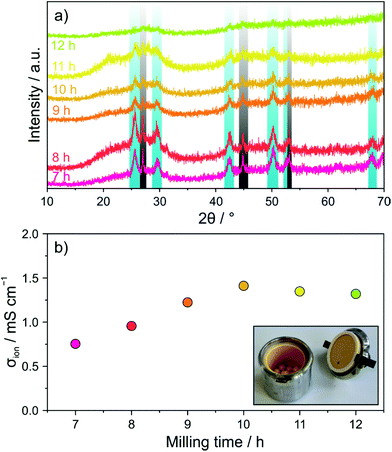
First, a mixture of Li2S, P2S5 and LiI, stoichiometrically equivalent to Li4PS4I (1.5Li2S–0.5P2S5–LiI), was subjected to ball milling and the evolution of the crystal structure was followed ex situ by PXRD. Fig. 1a shows PXRD patterns collected after different milling times from 7 to 12 h. Reflections of both Li2S (Fm![[3 with combining macron]](https://www.rsc.org/images/entities/char_0033_0304.gif) m space group) and LiI (Fm
m space group) and LiI (Fm![[3 with combining macron]](https://www.rsc.org/images/entities/char_0033_0304.gif) m space group) were still clearly visible after 7 h. In the further course of milling, they gradually vanished, thereby indicating that progressive amorphization occurred.
m space group) were still clearly visible after 7 h. In the further course of milling, they gradually vanished, thereby indicating that progressive amorphization occurred.
In order to probe the effect that ball milling has on the electrical (ionic) conductivity, EIS measurements at 25 °C were conducted on compressed pellets. The spectra obtained revealed both a partial semicircle and a capacitive tail (see Fig. S1 of the ESI†). With increasing milling time, the semicircle could hardly be resolved anymore, demonstrating increasing conductivity. Fitting of the experimental data was performed using an (R1Q1)Q2 equivalent circuit. The conductivity was calculated from the value of R1 and found to increase from ∼0.75 mS cm−1 for 7 h to ∼1.3 mS cm−1 (∼3.1 mS cm−1 at 45 °C) for 10 h (Fig. 1b). Although the PXRD pattern of the latter sample showed still some minor precursor reflections, longer ball milling did not lead to any further increases in conductivity.
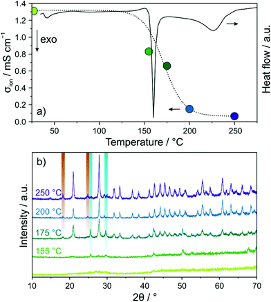
DSC was used to explore the glassy 1.5Li2S–0.5P2S5–LiI regarding phase transitions (Fig. 2a). Both a sharp peak at ∼160 °C and a relatively broad and less intense peak centered at 225 °C were observed. In order to gain insight into the phase composition(s) around these transitions, the sample after ball milling for 12 h was annealed in vacuum-sealed quartz ampoules for 12 h at different temperatures from 155 to 250 °C and then PXRD patterns were recorded (Fig. 2b). At 155 °C, just below the first transition region, minor reflections of LiI were visible. Upon increasing the temperature to 175 °C, new reflections appeared, which can be assigned to Li6PS5I (F![[4 with combining macron]](https://www.rsc.org/images/entities/char_0034_0304.gif) 3m space group) and Li4PS4I (P4/nmm space group). Higher temperatures led to more intense and narrower reflections of the tetragonal Li4PS4I phase due to progressive crystallization. Rietveld refinement of the PXRD pattern for the sample annealed at 250 °C yielded lattice parameters similar to those reported for Li4PS4I synthesized by a solution-based (wet chemistry) method (see Fig. S2 of the ESI†).18 The presence of crystalline Li6PS5I and LiI side products was estimated at ∼16 and ∼2 wt%, respectively.
3m space group) and Li4PS4I (P4/nmm space group). Higher temperatures led to more intense and narrower reflections of the tetragonal Li4PS4I phase due to progressive crystallization. Rietveld refinement of the PXRD pattern for the sample annealed at 250 °C yielded lattice parameters similar to those reported for Li4PS4I synthesized by a solution-based (wet chemistry) method (see Fig. S2 of the ESI†).18 The presence of crystalline Li6PS5I and LiI side products was estimated at ∼16 and ∼2 wt%, respectively.
Next, EIS measurements were performed again to follow the evolution of room-temperature ionic conductivity in the annealed samples (see Fig. S3 of the ESI†). The calculated values are displayed in Fig. 2a. Annealing at 155 °C already led to a drop in conductivity from ∼1.3 to ∼0.8 mS cm−1. The conductivity decreased further with increasing temperature, reaching ∼0.1 mS cm−1 after 250 °C. We note that the ionic conductivity of the solution-based Li4PS4I was about the same.18 Taken together, thermally induced crystallization of tetragonal Li4PS4I (and some other impurity phases) from the glassy 1.5Li2S–0.5P2S5–LiI was found to negatively affect the conductivity. This suggests that for the thiophosphate iodide material studied in the present work, disorder is beneficial to the Li-ion transport properties, in agreement with literature reports.20,24
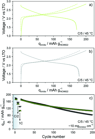
Because the glassy 1.5Li2S–0.5P2S5–LiI shows superior ionic conductivity over crystalline Li4PS4I, its performance in bulk-type (pellet stack) SSBs was analyzed in some detail. The cells comprised LiNbO3-coated NCM622, LTO, 1.5Li2S–0.5P2S5–LiI and Super C65 carbon black. For comparison reasons, identical cells with an argyrodite Li6PS5Cl solid electrolyte were simultaneously assembled and tested. Long-term cycling was performed at a rate of C/5 and 45 °C. The areal loading was ∼10 mgNCM622 cm−2. As shown in Fig. 3a, initial specific charge and discharge capacities of 201 and 172 mA h gNCM622−1 were achieved with the 1.5Li2S–0.5P2S5–LiI, corresponding to a coulombic efficiency of ∼86%. In the second cycle, the cells delivered a specific capacity of 172 mA h gNCM622−1 (∼1.7 mA h cm−2). Using the Li6PS5Cl solid electrolyte (Fig. 3b), initial specific charge and discharge capacities of 201 and 180 mA h gNCM622−1 were achieved. The difference in first-cycle coulombic efficiency (∼90% versus ∼86%) is indicative of more pronounced side reactions, probably solid electrolyte degradation, in the cells with the glassy 1.5Li2S–0.5P2S5–LiI. Some (minor) capacity fading was apparent during the first five cycles at C/5 rate (Fig. 3c). Upon increasing the C-rate to C/2, the specific discharge capacity dropped to 155 and 145 mA h gNCM622−1 for the Li6PS5Cl- and 1.5Li2S–0.5P2S5–LiI-based cells, respectively. This result can be explained by the difference in ionic conductivity, among others. Note that the electrical conductivity strongly affects the charge/discharge kinetics and this is particularly obvious when increasing the C-rate.29 As expected, the discrepancy between the specific discharge capacities was even larger at 1C rate, with 130 vs. 105 mA h gNCM622−1. In the further course of cycling at a rate of C/5, the cells showed similar fading, with specific capacities of ∼127 mA h gNCM622−1 (∼1.3 mA h cm−2) after 100 cycles. However, distinct differences regarding the capacity retention were noticeable at higher cycle numbers. While the Li6PS5Cl-based cells showed virtually linear fading, decelerated capacity decay was observed for the 1.5Li2S–0.5P2S5–LiI-based cells, with 82 vs. 105 mA h gNCM622−1 (∼1.0 mA h cm−2) after 200 cycles, corresponding to ∼46 and ∼61% capacity retention, respectively. The improved capacity retention was also somewhat reflected in the coulombic efficiency (see Fig. S4 of the ESI†). In fact, the 1.5Li2S–0.5P2S5–LiI-based cells were found to surpass 99% in the third cycle and it stabilized above 99.5% after 50 cycles (99.8% after 200 cycles). In contrast, for the cells using the Li6PS5Cl solid electrolyte, the rate of increase of the coulombic efficiency in the initial cycles was slower and even after 200 cycles, it was still below 99.5%. These observations apparently suggest that the glassy 1.5Li2S–0.5P2S5–LiI has a better electrochemical stability than Li6PS5Cl. However, considering the lower first-cycle coulombic efficiency and its evolution during the initial cycles, it rather seems that a thicker and probably more robust decomposition layer formed at the interfaces with the NCM622 and carbon black additive.27,30
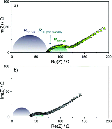
In order to gain more insight into the factors at play leading to the differences in capacity retention, EIS measurements at 45 °C were conducted on the cells after 200 cycles. As can be seen from the Nyquist plots of the electrochemical impedance in Fig. 4a and b, the measured spectra showed a depressed semicircle and a Warburg tail. Curve fitting was performed assuming an (R1Q1)(R2Q2)(R3Q3)Q4 equivalent circuit, where R1 is the solid electrolyte bulk (separator) resistance, R2 is the solid electrolyte grain boundary resistance and R3 represents primarily the cathode interfacial resistance.27,31 The calculated values of R1 are ∼39 and ∼69 Ω for the Li6PS5Cl- and 1.5Li2S–0.5P2S5–LiI-based cells, respectively. The larger value in the case of the thiophosphate iodide solid electrolyte can be explained by its lower ionic conductivity. Moreover, solid electrolyte grain boundary and cathode interfacial resistances of ∼7 and ∼32 Ω, respectively, were determined for the latter cells. In comparison, the respective resistances were found to be ∼18 and ∼5 Ω when using the argyrodite solid electrolyte. The higher cathode interfacial resistance in the 1.5Li2S–0.5P2S5–LiI-based cells agrees with the hypothesis that a more pronounced decomposition layer is formed in the initial cycle(s). The fact that the solid electrolyte grain boundary resistance was higher for Li6PS5Cl compared to the 1.5Li2S–0.5P2S5–LiI might hint at particle fracture (note that mechanical degradation is not necessarily limited to the CAM/solid electrolyte interface) considering that the solid electrolyte undergoes some deformation upon electrochemical cycling; however, this requires further study.
Apart from (electro)chemical instability issues, mechanical degradation because of volume expansion/contraction of the CAM particles has been recognized to play a key role in the performance of especially pelletized SSB cells.12,31 For NCM CAMs, the absolute relative volume changes upon charging increase with increasing Ni content.11–15 Hence, the use of lower stiffness solid electrolytes (higher elasticity)—provided that solid electrolyte degradation can be inhibited effectively, for example, by applying a protective surface coating to the CAM particles—appears to be beneficial to accommodate for local volume changes, thereby reducing the likelihood of mechanical failure.
In order to examine whether any microstructural changes occurred in the cathode layer in both the Li6PS5Cl- and 1.5Li2S–0.5P2S5–LiI-based cells, cross-sectional SEM images were collected before and after cycling. The spherical NCM622 secondary particles were clearly visible in both cases (Fig. 5a–d). However, as somewhat expected, more intimate physical contact between the solid electrolyte and the CAM was achieved when using the glassy 1.5Li2S–0.5P2S5–LiI. In addition, the cathode structure/morphology was reasonably well retained after 200 cycles (see also low-magnification SEM images in Fig. S5 of the ESI†). Subtle differences between the cathode layers can probably be attributed to some extent to the different mechanical properties of the solid electrolytes used. The greater mechanical softness of 1.5Li2S–0.5P2S5–LiI seems to help maintain sufficiently good physical contact between the individual components and mitigate void formation. This conclusion is also in agreement with the lower Young's modulus typically observed for amorphous (or glassy) thiophosphate-based solid electrolytes when compared to their crystalline counterparts.32–35 Moreover, we note that both NCM622 secondary particle fracture and electrode cracking were not apparent from the imaging data.
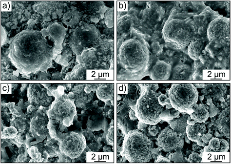 | ||
| Fig. 5 Cross-sectional SEM images of cathode layers with (a and b) the glassy 1.5Li2S–0.5P2S5–LiI and (c and d) Li6PS5Cl solid electrolyte (a and c) before and (b and d) after 200 cycles. | ||
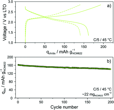
The glassy solid electrolyte was also tested in more practical SSB cells. To this end, cathodes of similar composition, but containing 1 wt% polyisobutylene binder, were manufactured using a slurry-casting process.3,28,36 The areal loading was ∼22 mgNCM622 cm−2. Specific charge and discharge capacities of 193 and 162 mA h gNCM622−1 (∼3.6 mA h cm−2) were achieved in the initial cycle (Fig. 6a). Interestingly, there was only a minor increase in charge/discharge overpotential (by ∼50 mV), despite the much higher CAM loading and the presence of a polymer binder. In addition, the first-cycle coulombic efficiency was only slightly lower compared to that of cells using the binder-free NCM622 cathode (∼83% versus ∼86%). However, it stabilized above 99.5% within the first five cycles and reached ∼100% after 25 cycles (see Fig. S6 of the ESI†), thus indicating high reversibility. As can be seen from Fig. 6b, the cell showed linear capacity decay with cycling and was still capable of delivering 141 mA h gNCM622−1 (∼3.1 mA h cm−2) after 200 cycles, corresponding to a capacity fade rate per cycle of only ∼0.065%.
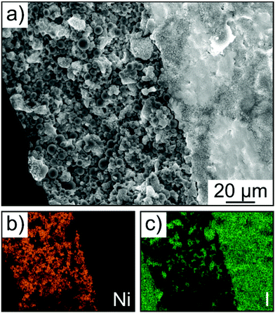
Finally, SEM and energy dispersive X-ray (EDX) spectroscopy confirmed that the cathode of thickness >100 μm was uniform over the entire cross section, without signs of delamination, major particle displacement or cracking (Fig. 7a–c). Hence, this result provides evidence that mechanical degradation can be mitigated further through implementation of a polymer binder.
Conclusions
In summary, the 1.5Li2S/0.5P2S5/LiI solid electrolyte phase system was characterized with respect to structure and electrical conductivity using PXRD, DSC and EIS. Ball milling-assisted amorphization of the precursor mixture resulted in increases in room-temperature ionic conductivity up to ∼1.3 mS cm−1. Subsequent annealing of the glassy 1.5Li2S–0.5P2S5–LiI at temperatures above 150 °C decreased the ionic conductivity considerably due to the formation of crystalline LiI, Li6PS5I and Li4PS4I. This result therefore suggests that for lithium-thiophosphate-iodide-based solid electrolytes, high conductivity can be achieved by introducing (long-range) structural disorder (i.e., in amorphous or glassy phases), in contrast to chlorine- and bromine-containing lithium thiophosphates.Moreover, pellet stack SSB cells with an NCM622 cathode and a LTO anode using the glassy 1.5Li2S–0.5P2S5–LiI solid electrolyte were found to outperform argyrodite Li6PS5Cl-based cells in terms of long-term performance. In addition, high-loading, slurry-cast cathodes were able to cycle stably (capacity fading of only ∼0.065% per cycle on average at C/5 rate and 45 °C) in the same cell configuration. This seems to be due to the 1.5Li2S–0.5P2S5–LiI, which not only allows intimate contact with the NCM622 secondary particles but also improves the microstructural integrity upon electrochemical cycling. In a broader context, the experimental data indicate that the mechanical properties of solid electrolytes must be considered more carefully in developing long-life, bulk-type SSBs.
Conflicts of interest
There are no conflicts to declare.Acknowledgements
F. S. acknowledges financial support through a Liebig fellowship from the Fonds der Chemischen Industrie (FCI). This project was supported by BASF SE. The authors also thank Dr A-Young Kim and Dr Yuan Ma (KIT) as well as Dr Holger Geßwein (KIT) for assistance in collecting SEM images and DSC data, respectively, and Dr Pascal Hartmann (BASF SE, Ludwigshafen) for fruitful project discussions.References
- J. Janek and W. G. Zeier, A solid future for battery development, Nat. Energy, 2016, 1, 16141 CrossRef.
- K. Kerman, A. Luntz, V. Viswanathan, Y.-M. Chiang and Z. Chen, Review–practical challenges hindering the development of solid state Li ion batteries, J. Electrochem. Soc., 2017, 164, A1731–A1744 CrossRef CAS.
- S. Ito, S. Fujiki, T. Yamada, Y. Aihara, Y. Park, T. Y. Kim, S.-W. Baek, J.-M. Lee, S. Doo and N. Machida, A rocking chair type all-solid-state lithium ion battery adopting Li2O–ZrO2 coated LiNi0.8Co0.15Al0.05O2 and a sulfide based electrolyte, J. Power Sources, 2014, 248, 943–950 CrossRef CAS.
- A.-Y. Kim, F. Strauss, T. Bartsch, J. H. Teo, T. Hatsukade, A. Mazilkin, J. Janek, P. Hartmann and T. Brezesinski, Stabilizing effect of a hybrid surface coating on a Ni-rich NCM cathode material in all-solid-state batteries, Chem. Mater., 2019, 31, 9664–9672 CrossRef CAS.
- M. Yamamoto, Y. Terauchi, A. Sakuda and M. Takahashi, Binder-free sheet-type all-solid-state batteries with enhanced rate capabilities and high energy densities, Sci. Rep., 2018, 8, 1212 CrossRef.
- S. H. Jung, U.-H. Kim, J.-H. Kim, S. Jun, C. S. Yoon, Y. S. Jung and Y.-K. Sun, Ni-rich layered cathode material with electrochemo-mechanically compliant microstructures for all-solid-state batteries, Adv. Energy Mater., 2020, 10, 1903360 CAS.
- Y.-G. Lee, S. Fujiki, C. Jung, N. Suzuki, N. Yashiro, R. Omoda, D.-S. Ko, T. Shiratsuchi, T. Sugimoto, S. Ryu, J. H. Ku, T. Watanabe, Y. Park, Y. Aihara, D. Im and I. T. Han, High-energy long-cycling all-solid-state lithium metal batteries enabled by silver–carbon composite anodes, Nat. Energy, 2020, 5, 299–308 CAS.
- Z. Gao, H. Sun, L. Fu, F. Ye, Y. Zhang, W. Luo and Y. Huang, Promises, challenges, and recent progress of inorganic solid-state electrolytes for all-solid-state lithium batteries, Adv. Mater., 2018, 30, 1705702 CrossRef.
- J. Lau, R. H. DeBlock, D. M. Butts, D. S. Ashby, C. S. Choi and B. S. Dunn, Sulfide solid electrolytes for lithium battery applications, Adv. Energy Mater., 2018, 8, 1800933 CrossRef.
- K. H. Park, Q. Bai, D. H. Kim, D. Y. Oh, Y. Zhu, Y. Mo and Y. S. Jung, Design strategies, practical considerations, and new solution processes of sulfide solid electrolytes for all-solid-state batteries, Adv. Energy Mater., 2018, 8, 1800035 Search PubMed.
- L. de Biasi, A. O. Kondrakov, H. Geßwein, T. Brezesinski, P. Hartmann and J. Janek, Between scylla and charybdis: balancing among structural stability and energy density of layered NCM cathode materials for advanced lithium-ion batteries, J. Phys. Chem. C, 2017, 121, 26163–26171 CrossRef.
- R. Koerver, W. Zhang, L. de Biasi, S. Schweidler, A. O. Kondrakov, S. Kolling, T. Brezesinski, P. Hartmann, W. G. Zeier and J. Janek, Chemo-mechanical expansion of lithium electrode materials – on the route to mechanically optimized all-solid-state batteries, Energy Environ. Sci., 2018, 11, 2142–2158 RSC.
- K. Ishidzu, Y. Oka and T. Nakamura, Lattice volume change during charge/discharge reaction and cycle performance of Li[NixCoyMnz]O2, Solid State Ionics, 2016, 288, 176–179 CrossRef CAS.
- H.-H. Ryu, K.-J. Park, C. S. Yoon and Y.-K. Sun, Capacity fading of Ni-rich Li[NixCoyMn1−x–y]O2 (0.6 ≤ x ≤ 0.95) cathodes for high-energy-density lithium-ion batteries: bulk or surface degradation?, Chem. Mater., 2018, 30, 1155–1163 CrossRef CAS.
- F. Strauss, L. de Biasi, A.-Y. Kim, J. Hertle, S. Schweidler, J. Janek, P. Hartmann and T. Brezesinski, Rational design of quasi-zero-strain NCM cathode materials for minimizing volume change effects in all-solid-state batteries, ACS Mater. Lett., 2020, 2, 84–88 CrossRef CAS.
- W. Zhang, D. Schröder, T. Arlt, I. Manke, R. Koerver, R. Pinedo, D. A. Weber, J. Sann, W. G. Zeier and J. Janek, (Electro)chemical expansion during cycling: monitoring the pressure changes in operating solid-state lithium batteries, J. Mater. Chem. A, 2017, 5, 9929–9936 RSC.
- F. Rosciano, M. Christensen, V. Eyert, A. Mavromaras and E. Wimmer, Reduced strain cathode materials for solid state lithium ion batteries, International publication numberWO2014/191018A1, 2014 Search PubMed.
- S. J. Sedlmaier, S. Indris, C. Dietrich, M. Yavuz, C. Dräger, F. von Seggern, H. Sommer and J. Janek, Li4PS4I: a Li+ superionic conductor synthesized by a solvent-based soft chemistry approach, Chem. Mater., 2017, 29, 1830–1835 CrossRef CAS.
- S. Sicolo, C. Kalcher, S. J. Sedlmaier, J. Janek and K. Albe, Diffusion mechanism in the superionic conductor Li4PS4I studied by first-principles calculation, Solid State Ionics, 2018, 319, 83–91 CAS.
- S. Ujiie, A. Hayashi and M. Tatsumisago, Structure, ionic conductivity and electrochemical stability of Li2S–P2S5–LiI glass and glass–ceramic electrolytes, Solid State Ionics, 2012, 211, 42–45 CrossRef CAS.
- N. H. H. Phuc, T. Yamamoto, H. Muto and A. Matsuda, Fast synthesis of Li2S–P2S5–LiI solid electrolyte precursors, Inorg. Chem. Front., 2017, 4, 1660–1664 RSC.
- K. Minami, A. Hayashi and M. Tatsumisago, Mechanochemical synthesis of Li2S–P2S5 glass electrolytes with lithium salts, Solid State Ionics, 2010, 181, 1505–1509 CrossRef CAS.
- E. Rangasamy, Z. Liu, M. Gobet, K. Pilar, G. Sahu, W. Zhou, H. Wu, S. Greenbaum and C. Liang, An iodide-based Li7P2S8I superionic conductor, J. Am. Chem. Soc., 2015, 137, 1384–1387 CrossRef CAS.
- R. Mercier, J.-P. Malugani, B. Fahys and G. Robert, Superionic conduction in Li2S-P2S5-LiI-glasses, Solid State Ionics, 1981, 5, 663–666 CrossRef CAS.
- F. Strauss, T. Bartsch, L. de Biasi, A.-Y. Kim, J. Janek, P. Hartmann and T. Brezesinski, Impact of cathode material particle size on the capacity of bulk-type all-solid-state batteries, ACS Energy Lett., 2018, 3, 992–996 CrossRef CAS.
- N. Ohta, K. Takada, I. Sakaguchi, L. Zhang, R. Ma, K. Fukuda, M. Osada and T. Sasaki, LiNbO3-coated LiCoO2 as cathode material for all solid-state lithium secondary batteries, Electrochem. Commun., 2007, 9, 1486–1490 CrossRef CAS.
- F. Strauss, D. Stepien, J. Maibach, L. Pfaffmann, S. Indris, P. Hartmann and T. Brezesinski, Influence of electronically conductive additives on the cycling performance of argyrodite-based all solid-state batteries, RSC Adv., 2020, 10, 1114–1119 RSC.
- T. Ates, M. Keller, J. Kulisch, T. Adermann and S. Passerini, Development of an all-solid-state lithium battery by slurry-coating procedures using a sulfidic electrolyte, Energy Storage Mater., 2019, 17, 204–210 CrossRef.
- A. Bielefeld, D. A. Weber and J. Janek, Microstructural modeling of composite cathodes for all-solid-state batteries, J. Phys. Chem. C, 2019, 123, 1626–1634 CrossRef CAS.
- F. Walther, S. Randau, Y. Schneider, J. Sann, M. Rohnke, F. H. Richter, W. G. Zeier and J. Janek, Influence of carbon additives on the decomposition pathways in cathodes of lithium thiophosphate-based all-solid-state batteries, Chem. Mater., 2020, 32, 6123–6136 CrossRef CAS.
- R. Koerver, I. Aygün, T. Leichtweiß, C. Dietrich, W. Zhang, J. O. Binder, P. Hartmann, W. G. Zeier and J. Janek, Capacity fade in solid-state batteries: interphase formation and chemomechanical processes in nickel-rich layered oxide cathodes and lithium thiophosphate solid electrolytes, Chem. Mater., 2017, 29, 5574–5582 CrossRef CAS.
- Z. Deng, Z. Wang, I.-H. Chu, J. Luo and S. P. Ong, Elastic properties of alkali superionic conductor electrolytes from first-principles calculations, J. Electrochem. Soc., 2016, 163, A67–A74 CrossRef CAS.
- F. P. McGrogan, T. Swamy, S. R. Bishop, E. Eggleton, L. Porz, X. Chen, Y.-M. Chiang and K. J. Van Vliet, Compliant yet brittle mechanical behavior of Li2S–P2S5 lithium-ion conducting solid electrolyte, Adv. Energy Mater., 2017, 7, 1602011 CrossRef.
- A. Kato, M. Yamamoto, A. Sakuda, A. Hayashi and M. Tatsumisago, Mechanical properties of Li2S–P2S5 glasses with lithium halides and application in all-solid-state batteries, ACS Appl. Energy Mater., 2018, 1, 1002–1007 CrossRef CAS.
- F. Han, J. Yue, X. Zhu and C. Wang, Suppressing Li dendrite formation in Li2S-P2S5 solid electrolytes by LiI incorporation, Adv. Energy Mater., 2018, 8, 1703644 CrossRef.
- Y. J. Nam, D. Y. Oh, S. H. Jung and Y. S. Jung, Toward practical all-solid-state lithium-ion batteries with high energy density and safety: comparative study for electrodes fabricated by dry- and slurry-mixing processes, J. Power Sources, 2018, 375, 93–101 CrossRef CAS.
Footnote |
| † Electronic supplementary information (ESI) available. See DOI: 10.1039/d0qi00758g |
| This journal is © the Partner Organisations 2020 |

