 Open Access Article
Enhancement of the electrochemical performance of lithium-ion batteries by SiO2@poly(2-acrylamido-2-methylpropanesulfonic acid) nanosphere addition into a polypropylene membrane
Guoping Yanga,
Haopeng Cai*ac,
Xiangyu Lia,
Mengjun Wub,
Xue Yina,
Haining Zhangb and
Haolin Tang *b
*b
aSchool of Materials Science and Engineering, Wuhan University of Technology, Wuhan 430070, China. E-mail: cai_haopeng@whut.edu.cn
bState Key Laboratory of Advanced Technology for Materials Synthesis and Processing, Wuhan University of Technology, Wuhan 430070, China. E-mail: thln@whut.edu.cn
cInstitute of Advanced Material Manufacturing Equipment and Technology, Wuhan University of Technology, Wuhan 430070, People's Republic of China
First published on 30th January 2020
Abstract
Employing electrostatic self-assembly and free radical polymerization, the surface of SiO2 nanospheres was coated with poly(2-acrylamido-2-methylpropanesulfonic acid) (SiO2@PAMPS) bearing strong electron withdrawing sulfonic and amide groups, enhancing the dissociation ability of the lithium salt of the liquid electrolyte and absorbing anions via hydrogen bonds. After SiO2@PAMPS nanospheres were introduced into the polypropylene (PP) membrane (SiO2@PAMPS/PP), the electrolyte affinity and electrolyte uptake of the composite separators were significantly improved. The ionic conductivity of SiO2@PAMPS/PP-18% (where 18% represents the concentration of the solution used for coating) soaked in liquid electrolyte was even 0.728 mS cm−1 at 30 °C, much higher than that of the pristine PP membrane. The LiFePO4/Li half-cell with SiO2@PAMPS/PP-18% had a discharge capacity of 148.10 mA h g−1 and retained 98.67% of the original capacity even after 120 cycles at 0.5C. Even at a rate of 1.0C, the cell capacity could be maintained above 120 mA h g−1. Therefore, a coating formula was developed that could considerably improve the cycling ability and high rate charge–discharge performance of lithium ion batteries.
1. Introduction
With the popularization and promotion of fifth generation (5G) information technology, commercial lithium ion batteries (LIBs) face extraordinary opportunities and challenges. The development direction of LIBs, nowadays, is towards high output power, high capacity, and fast charging mode.1–9 Therefore, the innovation of preparation technology related to the membrane of LIBs is also in urgent need of a breakthrough.10–12,12–16 Changqing Zhu et al. acquired an aramid nanofiber/polyphenylene sulfide (ANFs/PPS) nonwoven composite separator via a paper-making method.17 It was found that the introduction of polar ANFs is helpful for lithium-ion transfer between the electrodes, and the cycling retention rate of the battery with the composite separator consequently reached 92% at 0.5C, much higher than that of the cell with a PP membrane (73%). Hao Zhang et al. invented a cellulose-based LIB membrane fabricated with northern bleached softwood kraft pulp (NBSK), alkali-treated polysulfonamide (A-PSA) and cellulose nanofibers (CNFs).18 It was noted that the capacity retention rate of the battery with the NBSK/A-PSA/CNF membrane was 85.3% (110.25 mA h g−1) after 100 cycles compared to the initial capacity of 129.24 mA h g−1 at 0.5C, higher than that of the Celgard separator that had a 71.4% capacity retention. Heng Li et al. prepared a membrane based on hydroxyapatite nanowires (HAP NWs) and cellulose fibers (CFs) by vacuum filtration.19 The battery with the HAP/CF membrane showed an initial discharge capacity of 138.00 mA h g−1, which is higher than that of the cell using a PP membrane (130.10 mA h g−1) at 0.5C. Moreover, the stability over 145 cycles of charge–discharge at 1.0C between the two membrane systems is not much different.Although the new composite membranes prepared for LIBs are superior to polyolefin membranes in terms of electrochemical performance, they are not suitable for large-scale commercial application in terms of production cost and technological requirements.20–23 However, coating organic polymers or ceramic particles on traditional commercial membranes could not only improve the performance of the battery, but also reduce the cost and processing difficulty. Nowadays, the continuous innovation of coated solution formula has become a core competitiveness of major lithium battery enterprises. Jianhui Dai et al. used polydopamine (PDA) to coat ceramic particles and the skeleton of the pristine polyethylene (PE) separator to form an overall-covered self-supporting film.24 After 200 cycles of charge–discharge operated at 0.5C, the cell with the PE-SiO2@PDA membrane exhibited a capacity retention of 93.9%, which is higher than that of the pristine PE membrane (93.8%). Dan Li et al. employed polymer-lithiated poly(perfluoroalkylsulfonyl)imide (LiPFSI) with Al2O3 powder to form a coating on a commercial PE membrane.25 The LiPFSI/Al2O3-PE separator could retain 98% of the original capacity after 220 cycles at high C-rate (up to 2C), and the reversible capacity of the battery with the PE separator was decreased dramatically. Jiang et al. created a silica encapsulated nanofibrous separator (SENS), and the SiO2 coating layer is covalently bonded to the polymer nanofibers.26 Cycling performance was investigated at 0.1C at 20 °C, and the discharge capacity of the cell with the SENS was 153 mA h g−1, while that of the Celgard 2325 battery system was 141 mA h g−1. The academic atmosphere for membrane coating is vigorous and new coating formulations and techniques are emerging.
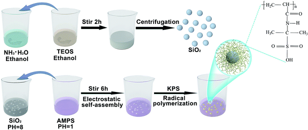
Due to the rigid support function of ceramics, the membrane modified with a ceramic had excellent thermal stability and dimensional integrity at high temperature.27–30 However, the coating of ceramics generally increases the impedance of the separator and reduces the charge–discharge capacity of the battery. Poly(2-acrylamido-2-methylpropanesulfonic acid) has been widely used in polymer electrolytes owing to its strong electron withdrawing sulfonic group and amide group, which are conducive to the dissociation of lithium salts and can absorb large volumes of anions through hydrogen bonding.31–36 Herein, 2-acrylamide-2-methyl-1-propane sulfonic acid (AMPS) monomer molecules were adsorbed onto the surface of SiO2 nanospheres by electrostatic self-assembly technology. After the addition of initiator, free radical polymerization of AMPS took place at 80 °C. The SiO2 nanospheres were enveloped with PAMPS to form new SiO2@PAMPS nanospheres. It was found that the introduced SiO2@PAMPS nanospheres in the PP membrane significantly improved the electrolyte affinity and electrolyte uptake, and were thus helpful to decrease the impedance and increase the ionic conductivity. These characteristics endowed the cell with superior rate capability and excellent cycling performance. Furthermore, the low cost of the materials for the preparing nanospheres makes the membrane coating more competitive. Hence, the SiO2@PAMPS/PP membrane could be a promising candidate for replacing commercial PP separators in industrial applications of LIBs.
2. Experimental
2.1. Synthesis of SiO2 nanospheres
After mixing 9 ml of concentrated ammonia water (Sinopharm Chemical Reagent Co., Ltd, Shanghai, China) with a concentration of 28%, 16.25 ml of ethanol (Sinopharm Chemical Reagent Co., Ltd, Shanghai, China) and 24.75 ml of deionized water, magnetic stirring was performed (Scheme 1). Then, a mixture of 4.5 ml of tetraethyl orthosilicate (TEOS, AR, Sinopharm Chemical Reagent Co., Ltd, Shanghai, China) and 45.5 ml of ethanol was quickly poured into the prepared solution. The mouth of the reaction flask was sealed with plastic wrap and the reaction continued for two hours at room temperature. Then, SiO2 nanospheres were prepared through centrifugation and cleaned with ethanol.2.2. Synthesis of SiO2@PAMPS nanospheres
A basic solution (pH = 8) was obtained by dissolving 1 g of SiO2 nanospheres in 80 ml of deionized water. Meanwhile, the surface of the SiO2 nanospheres was positively charged. Then, 6 g of 2-acrylamido-2-methylpropanesulfonic acid (AMPS, Aladdin Bio-Chem Technology Co., Ltd, Shanghai, China) powder was dissolved in 20 ml of deionized water to make an acidic solution (pH = 1). The acidic solution was poured into the alkaline solution, and the mixture was stirred magnetically for 30 minutes. AMPS monomers were tightly adsorbed on the surface of the SiO2 nanospheres through electrostatic self-assembly. Then, potassium persulfate (KPS, AR, Shanghai Experimental Reagent Co., ltd, Shanghai, China) was added to the solution for radical polymerization, nitrogen was added, and the mixture was heated to 80 °C for 6 h. As shown in Scheme 1, the SiO2 microspheres were coated by PAMPS. When the reaction system was cooled to room temperature, the mixed solution was removed and centrifuged, and cleaned with ethanol. Then SiO2@PAMPS nanospheres were obtained.2.3. Preparation of the separators
To prepare the solution for coating, various amounts of SiO2@PAMPS nanospheres were dissolved in N-methyl-2-pyrrolidone (NMP) under stirring at ambient temperature for 12 h. The concentration of SiO2@PAMPS microspheres (ω/ν) was 6%, 12%, 18%, 24%, and 30% respectively. Poly(vinylidene fluoride) (PVDF, HSV900, Arkema Co., Ltd, France) was used as the binder for membrane coating, and the mass ratio of PVDF and SiO2@PAMPS nanospheres was 1![[thin space (1/6-em)]](https://www.rsc.org/images/entities/char_2009.gif) :
:![[thin space (1/6-em)]](https://www.rsc.org/images/entities/char_2009.gif) 6. A commercial PP separator (Shenzhen Senior Technology Material Co., ltd, Shenzhen, China) was coated with the mixture solution using an automatic scraper to form an approximately 6 μm thick layer, and then dried in an oven at 60 °C for 24 h. The as-prepared membranes were cut into rounds with a diameter of 18 mm using a puncher. For convenience of expression, the composite membranes will be represented by SiO2@PAMPS/PP-X, where X represents the concentration of the solution used for coating.
6. A commercial PP separator (Shenzhen Senior Technology Material Co., ltd, Shenzhen, China) was coated with the mixture solution using an automatic scraper to form an approximately 6 μm thick layer, and then dried in an oven at 60 °C for 24 h. The as-prepared membranes were cut into rounds with a diameter of 18 mm using a puncher. For convenience of expression, the composite membranes will be represented by SiO2@PAMPS/PP-X, where X represents the concentration of the solution used for coating.
2.4. Characterization
The thickness of the composite membranes was tested using a thickness gauge (CH-1-S, Shenzhen Tianrui Instrument Co., Ltd, Shenzhen, China). The reported thickness was the average value from 5 individual measurements at different points of the membrane. The distribution of elements in individual SiO2@PAMPS nanospheres was characterized and measured by transmission electron microscope (TEM, JEM-2100F, Shanghai Juyi Testing Technology Co., Ltd, Shanghai, China). The morphologies of the composite separators were investigated by field emission scanning electron microscope (FE-SEM, S-4800, Hitachi, Tokyo, Japan). Suspensions of SiO2 nanospheres with different pH values were prepared and measured by a Zeta potential analyzer (NanoPlus HD, McMuritic Instruments Co., Ltd, Shanghai, China). The elements on the membrane surface were analyzed by X-ray photoelectron spectroscopy (ESCALAB 250Xi, Syme Fisher Technology Co., Ltd, Massachusetts, America). The contact angles (CAs) were measured with a contact angle meter (JC2000D, POWEREACH, Shanghai, China). The CA was determined by means of the sessile drop method, using electrolyte liquid (1.0 M LiPF6 solution in ethylene carbonate/diethyl carbonate, 1/3, v/v, Guangzhou Tinci Material Technology Co., Ltd, Guangdong, China) as the testing liquid. An electrolyte droplet with a volume of 5 μL was used for contact angle measurement. The electrolyte uptake of the relevant membranes was measured by immersing the membranes in the electrolyte for 30 minutes, removing the separators, and wiping off the electrolyte on the surface with filter paper, and then, the electrolyte uptake was calculated using eqn (1):| Electrolyte uptake (%) = (ω − ω0)/ω0 × 100% | (1) |
To measure the tensile strength of the membranes, the separators were sheared to the dimensions of 50 × 10 mm and determined on an Electromechanical Universal Testing Machine (CMT 6104, MTS Systems Co., Ltd, China) at a tensile speed of 5 mm min−1 at room temperature. The thermal properties of the composite separators were investigated by thermogravimetric analysis (TGA, STA449F3, Netzsch, Germany) at the rate of 10 °C min−1 under a nitrogen atmosphere from 30–600 °C. The calorimetric measurement was performed on a differential scanning calorimeter (DSC, Mettler Toledo Star System) in the range from 30–200 °C under a nitrogen atmosphere, and the heating rate was 5 °C min−1. The thermal shrinkage of the membranes was measured by placing the installed relevant separators between two pieces of glass in an oven at various temperatures from 125–185 °C for 0.5 h.
2.5. Electrochemical measurements
In order to make the experiment more rigorous and scientific, the electrolyte employed in the electrochemical measurements was a solution of 1.0 M LiPF6 in a mixture of organic carbonates (ethylene carbonate/diethyl carbonate = 1![[thin space (1/6-em)]](https://www.rsc.org/images/entities/char_2009.gif) :
:![[thin space (1/6-em)]](https://www.rsc.org/images/entities/char_2009.gif) 3, Guangzhou Tinci Material Technology Co., Ltd, Guangdong, China). To measure the ionic conductivities of the composite membranes, the polymer separators were immersed in the liquid electrolyte and sandwiched between two stainless steel (SS) electrodes with a test temperature ranging from 25 to 120 °C in an air circulating oven. The ionic conductivities were measured by an electrochemical workstation system (CHI660C, Shanghai Chenhua Co., Ltd, Shanghai, China) using the AC impedance spectroscopic technique at the frequency range from 1.0 Hz to 106 Hz. The ionic conductivity (σ) was calculated using eqn (2):
3, Guangzhou Tinci Material Technology Co., Ltd, Guangdong, China). To measure the ionic conductivities of the composite membranes, the polymer separators were immersed in the liquid electrolyte and sandwiched between two stainless steel (SS) electrodes with a test temperature ranging from 25 to 120 °C in an air circulating oven. The ionic conductivities were measured by an electrochemical workstation system (CHI660C, Shanghai Chenhua Co., Ltd, Shanghai, China) using the AC impedance spectroscopic technique at the frequency range from 1.0 Hz to 106 Hz. The ionic conductivity (σ) was calculated using eqn (2):| σ = L/(Rb × A) | (2) |
The activation energy was acquired by measuring the ionic conductivities of the membrane at different temperatures from 25 to 120 °C. The activation energy was calculated using eqn (3):
σ = A![[thin space (1/6-em)]](https://www.rsc.org/images/entities/char_2009.gif) exp(−Ea/RT) exp(−Ea/RT)
| (3) |
The electrochemical stability window of the separators soaked with the liquid electrolyte was evaluated in a cell of lithium/membrane/SS by linear sweep voltammetry (LSV) at 2 mV S−1 over the range of 2.5–5.0 V on an electrochemical workstation. For the evaluation of the charge–discharge cycling performance of the composite separators, the membranes were assembled into 2016 coin-type LiFePO4/Li half-cells in an argon-filled glove box. The cells were measured on battery test equipment (CT2001A, LAND Electronics, Wuhan, China) in the range from 2.5–4.0 V under current rates (C-rates) of 0.1–1.0C (1.0C = 170 mA h g−1). The cathode was prepared by mixing 80% LiFePO4 (Kejing Zhida Co., Ltd, Shenzhen, China), 10% PVDF and 10% super P (Timcal Graphite & Carbon, Switzerland), and the area density of the active substance was 1.30 mg cm−2.
3. Results and discussion
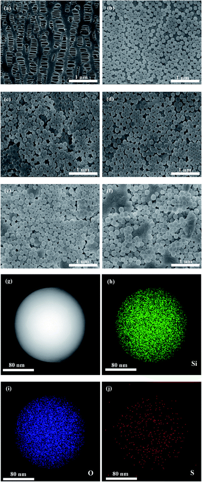
Fig. 1 depicts the surface morphologies of the pristine PP separator and composite membranes. The pristine PP membrane exhibited a mass of micropores, which could retain a certain amount of electrolyte and facilitate Li-ion diffusion. However, the morphology of the nanospheres with different concentrations on the membrane varies greatly. Compared with SiO2@PAMPS/PP-18%, the nanosphere distribution of SiO2@PAMPS/PP-6% and SiO2@PAMPS/PP-12% is looser, while the nanosphere distribution of SiO2@PAMPS/PP-24% and SiO2@PAMPS/PP-30% is too concentrated and the binder is not dispersed evenly, which leads to aggregation. The good distribution of the nanospheres is conducive to the contact between polar groups on the surface of the nanospheres and lithium salts in the electrolyte, thus improving the electrochemical performance. Furthermore, as shown in Fig. 1(g)–(j), PAMPS represented by S element is coated on the surface of the SiO2 nanospheres to form SiO2@PAMPS nanospheres.As shown in Fig. 2a, when the solution pH = 2, the surface of the SiO2 nanospheres is positively charged. However, the polymer monomer AMPS is always negatively charged. When the positively charged SiO2 nanospheres meet the negatively charged AMPS, electrostatic self-assembly will occur. PAMPS formed by radical polymerization was then coated on the surface of the SiO2 nanoparticles. Fig. 2b shows the analysis of elements on the surface of the composite separator by X-ray photoelectron spectroscopy. The 2p orbital electron binding energy peak of S was found at 164 eV, indicating that PAMPS coated the surface of the SiO2 nanospheres, while the 1s orbital electron binding energy peak of F was due to PVDF binder.
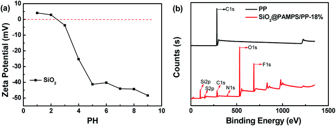 | ||
| Fig. 2 (a) The zeta potential of SiO2 nanospheres at different pH values. (b) X-ray photoelectron spectroscopy of the pristine PP separator and SiO2@PAMPS/PP-18%. | ||
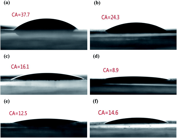
For liquid electrolyte batteries, the membrane can quickly and effectively absorb electrolyte, which is conducive to the improvement of the electrochemical performance.37,38 To quantitatively evaluate the electrolyte wetting of the membranes, the CAs of the electrolyte on the separator were measured (Fig. 3). Due to the low surface energy of the polyolefin separator, the PP membrane showed a high electrolyte contact angle of 37.7°. The static CAs for SiO2@PAMPS/PP-6%, SiO2@PAMPS/PP-12%, SiO2@PAMPS/PP-18%, SiO2@PAMPS/PP-24%, and SiO2@PAMPS/PP-30% were measured to be 24.3°, 16.1°, 8.9°, 12.5°, and 14.6°, respectively. The smaller contact angles of the SiO2@PAMPS/PP separators compared to that of the pristine PP membrane originate from the higher surface energy and outstanding hydrophilicity of the SiO2@PAMPS microspheres due to polar groups. SiO2@PAMPS/PP-18% has the smallest contact angle, and owing to the finer and more uniform coating, the electrolyte can be well distributed in the pores of the microspheres.
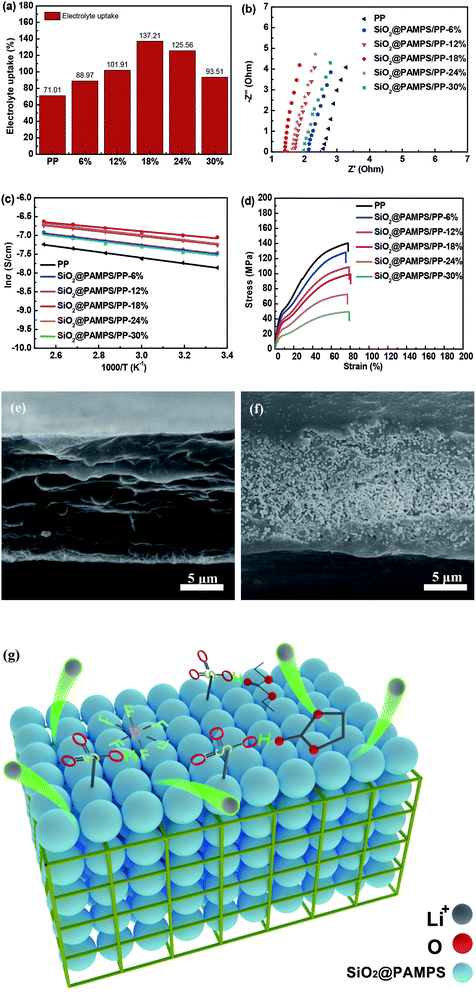
Generally, the smaller the contact angle of the membrane, the higher the electrolyte uptake.39–42 As shown in Fig. 4a, the electrolyte uptake was as high as 137.21% for SiO2@PAMPS/PP-18%, much higher than the 71.01% for the pristine PP membrane. The electrolyte uptake of the separators significantly affects the membrane ionic conductivity of the liquid electrolyte in Li-ion batteries. To evaluate the ionic conductivity, membranes immersed in liquid electrolyte were assembled into SS/Separator/SS cells to measure the AC impedance. Fig. 4b illustrates that the bulk resistances of the SiO2@PAMPS/PP separators are decreased, compared with the pristine PP separator. PAMPS contains robust polar groups, such as amide groups (–CO–NH–) and sulfonic groups (–HSO3), which are conducive to the dissociation of lithium salts. Meanwhile, the sulfonic group on the surface of the nanospheres forms hydrogen bonds with a large volume of anions and solvent molecules in the electrolyte, which enables the anions to adsorb on the surface of the nanospheres with a large specific surface area.43–48 As a result, the number of lithium ions increases and the rate of passing through the pores is accelerated, so that the impedance of the membrane immersed in the electrolyte decreases and the ionic conductivity increases (Fig. 4g). The ionic conductivity of SiO2@PAMPS/PP-18% soaked in liquid electrolyte, which has a fine uniform microsphere coating that can contact the electrolyte more fully, even reaches 0.728 mS cm−1 (Table 1).
| Separator | Thickness/μm | Resistance/Ω | Ionic conductivity/mS cm−1 |
|---|---|---|---|
| PP | 20 | 2.53 | 0.384 |
| SiO2@PAMPS/PP-6% | 20 | 2.13 | 0.456 |
| SiO2@PAMPS/PP-12% | 20 | 1.73 | 0.561 |
| SiO2@PAMPS/PP-18% | 21 | 1.40 | 0.728 |
| SiO2@PAMPS/PP-24% | 21 | 1.67 | 0.581 |
| SiO2@PAMPS/PP-30% | 22 | 2.17 | 0.447 |
The ionic conductivity of the PP membranes and composite separators at different temperatures is shown in Fig. 4c. The conductivity of the membranes generally increased with an increase in the temperature, but the activation energy calculated from the Arrhenius equation is quite different (Table 2). The PP membranes coated with SiO2@PAMPS nanospheres have lower activation energy than the pristine PP separator, and the activation energy of SiO2@PAMPS/PP is 4.44 kJ mol−1. This phenomenon demonstrated the promotion of free Li-ion migration in the coating layer by introducing the SiO2@PAMPS/PP nanospheres. This was ascribed to the flexible and super-delocalized nature of the –CO–NH– and –HSO3 structures in PAMPS, where Li-ions could be easily dissociated. The mechanical properties of the membrane are an essential indicator for commercial applications. The stress–strain curves showing the tensile strengths and elongation rates of the pristine PP separator and composite membrane are compared in Fig. 4d. The graph shows that the tensile strength decreases as the amount of SiO2@PAMPS increases, which is because the increase of the SiO2/PAMPS microsphere concentration weakens the skeleton structure of the PP membranes (Fig. 4e–f). As shown in the image of the cross section of SiO2@PAMPS/PP, the nanospheres are not only coated on the surface, but also penetrate into the skeleton structure of the PP membrane, which damages the mechanical structure of the PP separator. However, it should be note that the tensile strength of SiO2@PAMPS/PP-18% is 99.25 MPa, which may already be high enough for practical battery applications. In addition, the SiO2@PAMPS/PP membrane has a high elongation at break, similar to that of the pristine PP membrane.
| Separator | Slope | Ea/kJ mol−1 |
|---|---|---|
| PP | −0.76202 | 6.33 |
| SiO2@PAMPS/PP-6% | −0.67568 | 5.62 |
| SiO2@PAMPS/PP-12% | −0.63217 | 5.26 |
| SiO2@PAMPS/PP-18% | −0.53368 | 4.44 |
| SiO2@PAMPS/PP-24% | −0.65943 | 5.48 |
| SiO2@PAMPS/PP-30% | −0.68188 | 5.67 |
A comparison of the ion conductivities of separators coated with organic/inorganic materials in the current study and other studies is shown in Table 3, and SiO2@PAMPS/PP-18% had the highest ionic conductivity.49–52 This also proves the high surface energy and the ability to promote the diffusion of lithium ions of the SiO2@PAMPS. High ionic conductivity is conducive to the improvement of the electrochemical performance, which is of positive significance for commercial applications. In other words, the SiO2@PAMPS/PP is more competitive in the market compared with the composite separators of other studies.
| Material type | Electrolyte | Ion conductivity (mS cm−1) | Ref. |
|---|---|---|---|
| Al2O3/PPTA-coated PE | 1.0 M LiPF6 in DEC/EC/DMC | 0.474 | 49 |
| LiPFSI/Al2O3-coated PE | 1.0 M LiPF6 in EC/DMC/EMC | 0.550 | 25 |
| ZSM5-coated PP | 1.0 M LiPF6 in DEC/EC/DMC | 0.520 | 50 |
| LSO-SiO2@PE | 1.0 M LiPF6 in EC/DMC/EMC | 0.410 | 51 |
| PET/PP-20% | 1.0 M LiPF6 in DEC/EC/DMC | 0.665 | 52 |
| SiO2@PAMPS/PP-18% | 1.0 M LiPF6 in EC/DEC | 0.728 | The current study |
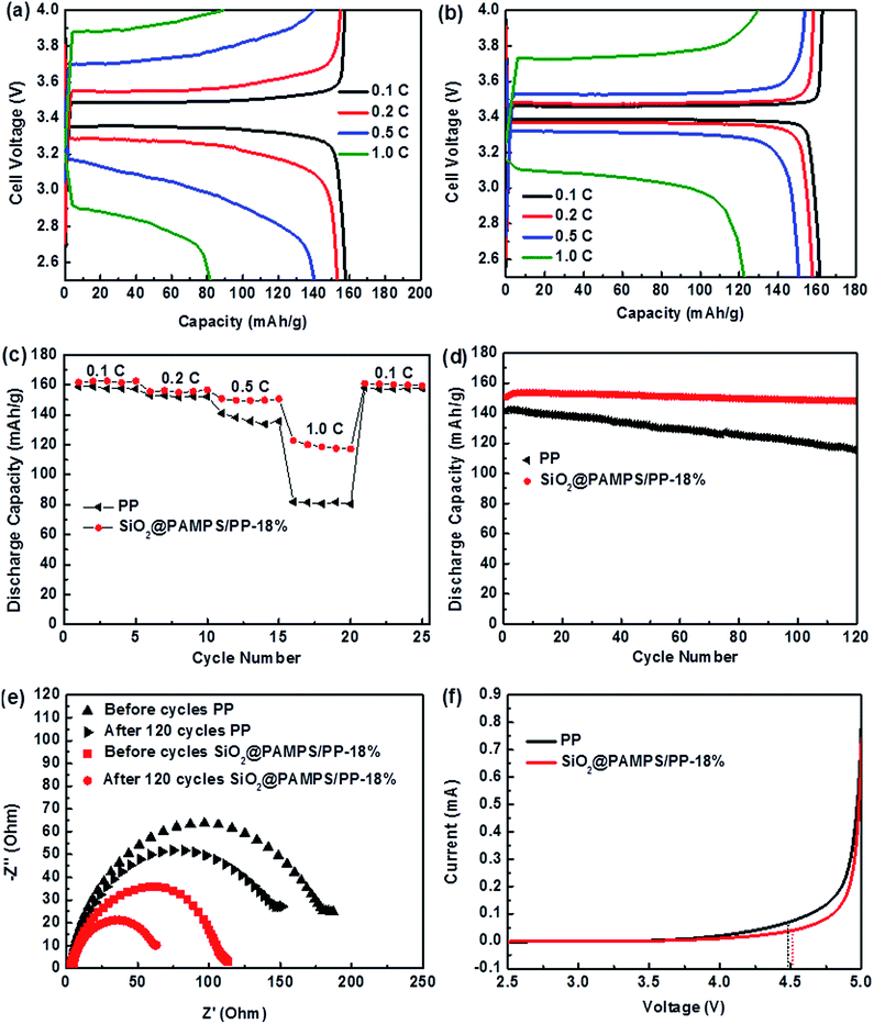
To clearly elucidate the influence of the introduction of SiO2@PAMPS nanospheres on the coated membrane, LiFePO4/Li half cells with pristine PP and SiO2@PAMPS/PP-18% membranes were assembled and the charge–discharge performance was measured. Fig. 5a–c illustrates that the specific capacity of charge–discharge of SiO2@PAMPS/PP-18% is higher than that of the pristine PP membrane at a high C-rate, which is attributed to preferable interfacial compatibility between the coating of SiO2@PAMPS nanospheres and the lithium cathode (Fig. 5e). During the charging and discharging processes, the lithium metal reacts with the components in the liquid electrolyte to form passivation layers that affect the transfer of lithium ions. A thin and uniform passivation layer is conducive to the disengagement and inlaying of lithium ions on the lithium anode and presents a low Rint and high charge–discharge capacity. Under high C-rates, the effect of solvent molecules trapped by hydrogen bonds of PAMPS is more obvious, and the growth of the passivation layer is slower and the structure is more uniform than in the cells assembled with PP separator. Therefore, the charge–discharge performance of SiO2@PAMPS/PP-18% is extremely superior at high C-rates. As indicated in Fig. 5d, the half-cell with SiO2@PAMPS/PP-18% showed improved cycling performance compared to the pristine PP membrane. The battery assembled with SiO2@PAMPS/PP-18% had a discharge capacity of 148.10 mA h g−1 and retained 98.67% of the original capacity even after 120 cycles. In contrast, the reversible capacity of the battery with the PP membrane decreased to 114.56 mA h g−1 and 80.67% of the original discharge capacity was retained after 120 cycles. The (–CO–NH–) and (–HSO3) polar groups of the SiO2@PAMPS nanospheres promote the dissociation of Li-ions from the anions and restrict the anion diffusion, the Li-ion transport capacity is enhanced and the cell impedance is effectively reduced. These factors indeed assisted the battery in maintaining stability during long-term cycling. Moreover, the coating of SiO2@PAMPS nanospheres could retain a considerable quantity of electrolyte after long-term cycling. The superior chemical stability of PAMPS also contributes to the improvement in the electrochemical cycling stability.
Fig. 5e depicts the variations in the impedance spectra of the membranes before and after 120 cycles at 0.5C. Under charging–discharging processes, a solid electrolyte interface (SEI) layer will be formed on the surface of the lithium anode, and the Rint between the SEI and the membrane is less than that between the lithium metal and separator. After 120 cycles, the Rint of SiO2@PAMPS/PP-18% was significantly lower than that of the PP membrane, which was attributed to the slow and uniform growth of a SEI film.
Linear sweep voltammetry is a crucial method to evaluate the influence of a membrane on electrolyte stability (Fig. 5f). When the scanning voltage reaches a critical value, the decomposition of the electrolyte increases, resulting in a dramatic increase in the anode current.53,54 Meanwhile, the voltage value can be considered as the upper limit of the voltage that can be tolerated when the electrolyte is used. Fig. 5f shows that the decomposition voltage of the SiO2@PAMPS/PP-18% composite membrane is basically the same as that of the PP separator, both about 4.5 V. Considering the fact that commercial batteries charge and discharge below 4.5 V (vs. Li/Li+), the electrochemical stability of SiO2@PAMPS/PP-18% is high enough for commercial battery applications.
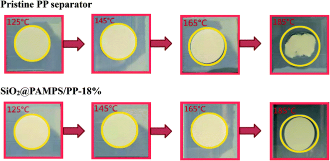
Under high power output or high temperature, the separator of lithium batteries can exhibit severe thermal shrinkage, which leads to short circuiting of the cells with safety problems.55–58 As presented in Fig. 6, the SiO2@PAMPS/PP-18% maintains complete dimensional stability at 165 °C, and the thermal shrinkage is inferior to that of the pristine PP membrane at 185 °C owing to the excellent heat resistance of the SiO2 particles.
To further study the influence of different concentrations of SiO2@PAMPS nanospheres on the thermal stability of the PP membrane, DSC measurements were further conducted (Fig. 7a). The pristine PP separator melted at 165 °C, while the melting temperature of all of the SiO2@PAMPS composite membranes slightly increased to 167 °C owing to the assistance of the SiO2 particles. With increasing SiO2@PAMPS nanosphere concentration, the thermal decomposition temperature of the composite membranes obviously increased from 400 °C to 480 °C (Fig. 7b). It should be noted that SiO2 particles with desirable thermal stability are not thermally decomposed at 700 °C, which is the reason for the improvement in the thermal stability of the composite membranes.
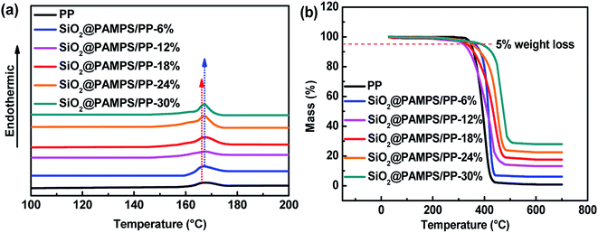 | ||
| Fig. 7 (a) DSC and (b) TG curves of the pristine PP membrane and SiO2@PAMPS/PP composite separators. | ||
4. Conclusion
In this study, the surface of SiO2 nanospheres was coated with PAMPS, which was beneficial to lithium ion conduction, by means of electrostatic self-assembly and free radical polymerization. PAMPS with polar (–CO–NH–) and (–HSO3) groups could promote the dissociation of lithium salts in the electrolyte, while hydrogen bonding of the groups could lead to the adsorption of large volumes of anions and solvent molecules. Compared to a commercial PP membrane, the composite separator with SiO2@PAMPS nanospheres soaked in electrolyte showed superior thermal resistance, higher electrolyte uptake, and higher ionic conductivity. The SiO2@PAMPS/PP-18% had the highest ionic conductivity (0.728 mS cm−1) and offered improved rate capability and cycling performance. At the charge–discharge current rate of 0.5C, the discharge capacity of the battery with SiO2@PAMPS/PP-18% reached 148.10 mA h g−1 and 98.67% of the original reversible capacity was retained after 120 cycles. Furthermore, the discharge capacity of the battery with SiO2@PAMPS/PP-18% could remain at 117.15 mA h g−1. The results indicate that the SiO2@PAMPS/PP-18% membrane with improved safety and excellent electrochemical performance could be a promising candidate for replacing commercial PP separators in the industrial application of LIBs.Conflicts of interest
The authors declare no conflict of interest.Acknowledgements
We gratefully acknowledge the funding from the National Nature Science Foundation of China (61376064) and the Fundamental Research Funds for the Central Universities (WUT: 2019III070GX).References
- F. Peng, D. Mu, R. Li, Y. Liu, Y. Ji, C. Dai and F. Ding, RSC Adv., 2019, 9, 21922–21930 RSC.
- J. Cheng, T. Lu, X. Wu, H. Zhang, C. Zhang, C.-A. Peng and S. Huang, RSC Adv., 2019, 9, 22729–22739 RSC.
- M. Shimizu, T. Ohnuki, T. Ogasawara, T. Banno and S. Arai, RSC Adv., 2019, 9, 21939–21945 RSC.
- J. Y. Cheong, S. Lee, J. Lee, H. Lim, S.-H. Cho, D. C. Lee and I.-D. Kim, RSC Adv., 2019, 9, 27257–27263 RSC.
- H. Wen, W. Kang, X. Liu, W. Li, L. Zhang and C. Zhang, RSC Adv., 2019, 9, 23607–23613 RSC.
- B. N. Choi, J. H. Yang, Y. S. Kim and C.-H. Chung, RSC Adv., 2019, 9, 21760–21770 RSC.
- Y. Park, M. Oh, Y. Lee and H. Park, RSC Adv., 2019, 9, 21444–21450 RSC.
- F. An, R. Zhang, Z. Wei and P. Li, RSC Adv., 2019, 9, 21498–21506 RSC.
- K. Zhang, T. H. Lee, B. Bubach, M. Ostadhassan, H. W. Jang, J.-W. Choi and M. Shokouhimehr, RSC Adv., 2019, 9, 26668–26675 RSC.
- N. Li, J. Guo, Z. Chang, H. Dang, X. Zhao, S. Ali, W. Li, H. Zhou and C. Sun, RSC Adv., 2019, 9, 23908–23915 RSC.
- Z. Meng, S. Wang, H. Wang, L. Wang and S. Wang, RSC Adv., 2019, 9, 20618–20623 RSC.
- H. Nan, Y. Zhang, H. Wei, H. Chen, C. Xue, G. Yang, S. Zou, G. Wang and H. Lin, RSC Adv., 2019, 9, 22101–22105 RSC.
- K. Shimoda, K. Koganei, T. Takeuchi, T. Matsunaga, M. Murakami, H. Sakaebe, H. Kobayashi and E. Matsubara, RSC Adv., 2019, 9, 23979–23985 RSC.
- Y. Ren, RSC Adv., 2019, 29760–29764 RSC.
- H. Zhang, B. Tian, J. Xue, G. Ding, X. Ji and Y. Cao, RSC Adv., 2019, 9, 24682–24687 RSC.
- H. Wang, M. Kalubowilage, S. H. Bossmann and P. B. Amama, RSC Adv., 2019, 9, 27927–27936 RSC.
- C. Zhu, J. Zhang, J. Xu, X. Yin, J. Wu, S. Chen, Z. Zhu, L. Wang and H. Wang, J. Membr. Sci., 2019, 588, 117169 CrossRef CAS.
- H. Zhang, X. An, L. Liu, Z. Lu, H. Liu and Y. Ni, J. Membr. Sci., 2019, 591, 117346 CrossRef CAS.
- H. Li, D. Wu, J. Wu, L.-Y. Dong, Y.-J. Zhu and X. Hu, Adv. Mater., 2017, 29, 1703548 CrossRef PubMed.
- H. Li, B. Zhang, W. Liu, B. Lin, Q. Ou, H. Wang, M. Fang, D. Liu, S. Neelakandan and L. Wang, Electrochim. Acta, 2018, 290, 150–164 CrossRef CAS.
- Z. Chen, T. Gang, K. Zhang, J. Zhang, X. Chen, Z. Sun and B. Yang, Colloids Surf., A, 2006, 272, 151–156 CrossRef CAS.
- N. Wei, J. Hu, M. Zhang, J. He and P. Ni, Electrochim. Acta, 2019, 307, 495–502 CrossRef CAS.
- S. Feng, D. Shi, F. Liu, L. Zheng, J. Nie and W. Feng, Electrochim. Acta, 2013, 93, 254–263 CrossRef CAS.
- J. Dai, C. Shi, C. Li, X. Shen, L. Peng, D. Wu, D. Sun, P. Zhang and J. Zhao, Energy Environ. Sci., 2016, 3252–3261 RSC.
- L. Dan, D. Qin, N. Feng, L. Wen and L. Xue, J. Mater. Sci., 2018, 53, 1–12 CrossRef.
- F. Jiang, Y. Nie, L. Yin, Y. Feng, Q. Yu and C. Zhong, J. Membr. Sci., 2016, 510, 1–9 CrossRef CAS.
- P. Ram, A. Gören, R. Gonçalves, G. Choudhary, S. Ferdov, M. M. Silva, R. Singhal, C. M. Costa, R. K. Sharma and S. Lanceros-méndez, Composites, Part B, 2018, 139, 55–63 CrossRef CAS.
- E. Stojanovska, E. Serife, A. Kilic, M. Quddus and Z. Candan, Composites, Part B, 2019, 158, 239–248 CrossRef CAS.
- S. Wu, Y. Han, K. Wen, Z. Wei, D. Chen, W. Lv, T. Lei, J. Xiong, M. Gu and W. He, Composites, Part B, 2019, 161, 369–375 CrossRef CAS.
- W. Liu, Y. Fu, Y. Li, S. Chen, Y. Song and L. Wang, Composites, Part B, 2019, 163, 464–470 CrossRef CAS.
- H. Zhang, X. Zhang, E. Shiue and P. S. Fedkiw, J. Power Sources, 2008, 177, 561–565 CrossRef CAS.
- W. Cui and D. Tang, J. Appl. Polym. Sci., 2012, 126, 510–518 CrossRef CAS.
- W. Wei, C. Dong, Y. Tang, Y. Shan, L. Na, Z. Li and Z. Liu, Iran. Polym. J., 2017, 26, 179–191 CrossRef.
- Y. Zhu, M. Yin, H. Liu, B. Na, R. Lv, B. Wang and Y. Huang, Composites, Part B, 2017, 112, 31–37 CrossRef CAS.
- M. Kundu, G. Attila, L. Liu, S. Lanceros-m and C. M. Costa, Composites, Part B, 2016, 96, 94–102 CrossRef.
- T. Carlson and L. E. Asp, Composites, Part B, 2013, 49, 16–21 CrossRef CAS.
- W. W. Cui, D. Y. Tang, Z. L. Gong and Y. Di Guo, J. Mater. Sci., 2012, 47, 6276–6285 CrossRef CAS.
- Q. Han, W. Zhang, Z. Han, F. Wang, D. Geng, X. Li, Y. Li and X. Zhang, J. Mater. Sci., 2019, 54, 11972–11982 CrossRef CAS.
- L. Xiong, H. Wang, W. Xiong, S. Yu and C. Ouyang, RSC Adv., 2019, 9, 27378–27385 RSC.
- A. Hosseinioun, P. Nürnberg, M. Schönhoff, D. Diddens and E. Paillard, RSC Adv., 2019, 9, 27574–27582 RSC.
- L. A. Selis and J. M. Seminario, RSC Adv., 2019, 9, 27835–27848 RSC.
- P. Kumari, K. Awasthi, S. Agarwal, T. Ichikawa, M. Kumar and A. Jain, RSC Adv., 2019, 29549–29555 RSC.
- K. Mishra, X. Liu, F. Ke and X. Zhou, Composites, Part B, 2019, 163, 158–164 CrossRef CAS.
- C. Chen, N. Pu, Y. Liu, L. Chen, C. Wu, T. Cheng, M. Lin, M. Ger, Y. Gong, Y. Peng, P. M. Grubb and R. T. Chen, Composites, Part B, 2018, 135, 119–128 CrossRef CAS.
- D. D. L. Chung, Composites, Part B, 2019, 160, 644–660 CrossRef CAS.
- J. Zang and Y. Zhao, Composites, Part B, 2012, 43, 76–82 CrossRef.
- J. Kumar, H. Takagi, A. Norio, D. Ram and S. Ahn, Composites, Part B, 2012, 43, 2822–2826 CrossRef.
- A. Pupurs and J. Varna, Composites, Part B, 2014, 65, 69–79 CrossRef CAS.
- H. Cai, G. Yang, Z. Meng, X. Yin, H. Zhang and H. Tang, Ploymers, 2019, 11, 1362 CrossRef CAS PubMed.
- X. Dong, W. Mi, L. Yu, Y. Jin and Y. S. Lin, Microporous Mesoporous Mater., 2016, 226, 406–414 CrossRef CAS.
- H. Zheng, Z. Wang, L. Shi, Y. Zhao and S. Yuan, J. Colloid Interface Sci., 2019, 554, 29–38 CrossRef CAS PubMed.
- H. Cai, X. Tong, K. Chen, Y. Shen, J. Wu, Y. Xiang, Z. Wang and J. Li, Polymers, 2018, 10, 574 CrossRef PubMed.
- X. Yang, Y. Ding, Z. Shen, Q. Sun, F. Zheng, H. Fong, Z. Zhu, J. Liu, J. Liang and X. Wang, J. Mater. Sci., 2019, 54, 11574–11584 CrossRef CAS.
- Y. Wu, Y. Chen, L. Jie, R. Chu, Z. Jian, C. Wu and G. Hang, J. Mater. Sci., 2017, 52, 1–10 CrossRef.
- X. Shen, Z. Li, N. Deng, W. Kang and J. Fan, Electrochim. Acta, 2019, 318, 801–808 CrossRef CAS.
- K. Xu, Y. Qin, T. Xu, X. Xie, J. Deng, J. Qi and C. Huang, J. Membr. Sci., 2019, 592, 117364 CrossRef CAS.
- N. Baig and T. A. Saleh, Composites, Part B, 2019, 173, 106805 CrossRef CAS.
- Z. Dan, W. Li, Z. Rong, Y. Ma and W. Yang, Polym. Eng. Sci., 2017, 58, 1 Search PubMed.
| This journal is © The Royal Society of Chemistry 2020 |

