 Open Access Article
Foldable water-activated reserve battery with diverse voltages†
Do-Hyun Kim *a,
In-Yeob Naa,
Duck Hyun Leeb and
Gyu Tae Kim
 *a
*a
aSchool of Electrical Engineering, Korea University, 145, Anam-ro, Seongbuk-gu, Seoul 02841, Republic of Korea. E-mail: nanotube@korea.ac.kr
bGreen Materials and Processes Group, Korea Institute of Industrial Technology, Ulsan, 44413, Republic of Korea
First published on 2nd January 2020
Abstract
A reserve battery is a device which is inert until its activation and generates electricity by injecting an electrolyte for the purpose of immediate use. Due to a relatively short history and the use in restricted fields, reserve batteries have not attracted attention without any technical advance such as be being flexible and foldable. In this study, we demonstrate a way of fabricating a flexible and even foldable reserve battery which is activated by various solutions. A paper electrode composed of cellulose and carbon nanotube, which is working as a cathode, was assembled with a sheet of an aluminum anode. The injection of a NaCl solution resulted in approximately 0.7 V while a KOH solution led to a much higher voltage of 1.3 V than the NaCl electrolyte. Impedance analysis unveiled that the best discharge performance was found in the reserve battery showing the smallest semicircle in impedance spectra, irrespective of electrolytes. And, folding the battery did not degrade the discharge performance, compared with an unfolded battery. Furthermore, the battery cell was even activated by seawater, resulting in about 0.7 V and a nice discharge performance. We think that our battery system can be extended to other reserve batteries requiring flexibility and foldability.
1. Introduction
A battery is a device that produces electricity from chemical reactions and is used in all aspects of daily life. Recently, with growing interest in flexible1–4 and wearable devices,5–8 intensive attention has been given to the research and development of batteries as a power source. Generally, a battery can not avoid a self-discharging problem whether it is a primary or secondary battery. Especially, the self-discharge takes place inevitably when batteries are used after long-term storage. A reverse battery can be an alternative to overcome the problem of self-discharge since it is a battery stored in an inactivated state and is activated when the battery needs to be used. The reserve battery can be classified into water-activated,9–11 gas-activated,12–14 and heat-activated batteries,15–17 depending on an activating mechanism. Among them, water-activated batteries are quite attractive because they can be easily activated by injecting fresh water18 or seawater.19–23 The water-activated battery was developed in 1940s to satisfy a request for a high-energy-density, long-shelf-life battery for marine applications. It has been known that the reserve battery also has good low-temperature performance, and been used in weather balloons, sonobuoys, radiosondes, electric torpedoes.24With the rapid advances in flexible and wearable devices, much attention was paid to the development of a flexible battery. As a result, many works contributed to the realization of various kinds of flexible batteries.25–31 However, most successes in a flexible battery are intensively focused on the Li ion battery. Particularly, less interest has been given to a reserve battery, compared with a secondary battery. Furthermore, a flexible and even foldable reserve battery has not been investigated up to now in spite of the merit such as a long shelf life without the self-discharge problem. And, most of the reserve batteries are still restricted to a conventional structure which can not change its shape freely. This situation motivated us to investigate a thin and foldable water-activated reserve battery.
In this work, we demonstrate a way of fabricating a foldable reserve battery activated by injecting a solution as an electrolyte. Among diverse battery systems known as metal–air batteries producing electricity by using metal and oxygen,32–34 we selected an aluminum–air battery system that usually uses aluminum as an anode and carbon for air cathode. It is because aluminum as well as carbon is cheap, light, and the third abundant element in the earth. Furthermore, it has been known that the aluminum–air battery results in a higher energy density (17![[thin space (1/6-em)]](https://www.rsc.org/images/entities/char_2009.gif) 300 W h L−1) in comparison with other metal–air batteries (sodium–air: 3
300 W h L−1) in comparison with other metal–air batteries (sodium–air: 3![[thin space (1/6-em)]](https://www.rsc.org/images/entities/char_2009.gif) 870 W h L−1, zinc–air: 6
870 W h L−1, zinc–air: 6![[thin space (1/6-em)]](https://www.rsc.org/images/entities/char_2009.gif) 220 W h L−1, lithium–air: 10
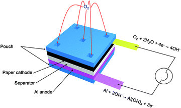
220 W h L−1, lithium–air: 10![[thin space (1/6-em)]](https://www.rsc.org/images/entities/char_2009.gif) 600 W h L−1).34 For a battery to be flexible and even foldable, all parts such as an anode, a cathode, and a separator should be bendable without degrading the original properties in their deformed states. To satisfy this, we fabricated a paper electrode composed of multi-walled carbon nanotubes (MWCNTs) and cellulose. Previous studies reported that MWCNTs have an electrochemical activity toward oxygen reduction reaction (ORR) in both acidic and alkaline conditions.35–40 Hence, this electrode was designed to work as a cathode for ORR and to be flexible and foldable freely. Moreover, this paper electrode plays as a role of a reservoir for an electrolyte injected to the reserve battery. As shown in Fig. 1, the single cell of a primary reserve battery was constituted by assembling the paper electrode and a sheet of aluminum with a separator. And, holes were created in the pouch covering the paper electrode for the purpose of both air supply and solution injection. When the solution is injected to the reserve battery, electricity is generated via the oxidation of aluminum sheet by the oxygen in the air (anode: Al + 3OH− → Al(OH)3 + 3e−, cathode: O2 + 2H2O + 4e− → 4OH−). Depending on the type of a liquid containing different ions, the battery generated different voltages of 0.7 and 1.3 V. Surprisingly, the reserve battery was activated by even seawater, resulting in a voltage of about 0.7 V. Furthermore, folding and crumpling battery did not influence the battery performance.
600 W h L−1).34 For a battery to be flexible and even foldable, all parts such as an anode, a cathode, and a separator should be bendable without degrading the original properties in their deformed states. To satisfy this, we fabricated a paper electrode composed of multi-walled carbon nanotubes (MWCNTs) and cellulose. Previous studies reported that MWCNTs have an electrochemical activity toward oxygen reduction reaction (ORR) in both acidic and alkaline conditions.35–40 Hence, this electrode was designed to work as a cathode for ORR and to be flexible and foldable freely. Moreover, this paper electrode plays as a role of a reservoir for an electrolyte injected to the reserve battery. As shown in Fig. 1, the single cell of a primary reserve battery was constituted by assembling the paper electrode and a sheet of aluminum with a separator. And, holes were created in the pouch covering the paper electrode for the purpose of both air supply and solution injection. When the solution is injected to the reserve battery, electricity is generated via the oxidation of aluminum sheet by the oxygen in the air (anode: Al + 3OH− → Al(OH)3 + 3e−, cathode: O2 + 2H2O + 4e− → 4OH−). Depending on the type of a liquid containing different ions, the battery generated different voltages of 0.7 and 1.3 V. Surprisingly, the reserve battery was activated by even seawater, resulting in a voltage of about 0.7 V. Furthermore, folding and crumpling battery did not influence the battery performance.
We think that our primary battery system can be extended to other metal–air batteries for the purpose of flexibility and foldability. Depending on the application, many small cells can be integrated into a single battery by connecting them in series in order to generate a higher voltage than 1.3 V. For example, the battery system suggested in this study can be modulated by varying the size and arrangement of cells, leading to diverse voltage, specific capacity, and power. We expect that when our reserve battery is equipped in a life jacket with a heating element, it can contribute to the delay of hypothermia due to the heat generated by the battery activated by seawater in the sea.
2. Experimental
Fabrication of paper electrode
The paper electrode was prepared by the method described in a previous work.41 At first, 1000 ml of deionized water was poured into a kitchen mixer grinder. Then, 3 g of shredded waste paper and 0.33 g of MWCNTs were added to the deionized water. The mixture was mechanically ground and mixed for 4 min in the absence of a dispersion agent. Next, 100 ml of the mixture was filtered under vacuum by using a Büchner funnel (diameter: 9.5 cm) with filter paper (Advantec 5C, diameter: 9 cm). The filtered mixture was dried and pressed by an office laminator to achieve the paper electrode with an even surface.Characterization of paper electrode
Sheet resistance and thickness of the paper electrode were measured by the four-point probe method (Laresa-GP, MCP-T600) and micrometer (Mitutoyo, Tokyo, Japan), respectively. For reproducibility, five sheets of paper were used in the characterization of sheet resistance and thickness. All measurements were performed at five different sites on the paper electrode. Scanning electron microscope (SEM, MIRA 3 FEG SEM) analysis was conducted to observe the morphology of the MWCNTs in the electrode.Assembly and activation of reserve batteries
As a first step, aluminum foil (thickness: avg. 17 μm, size: 6 cm × 6 cm) and the paper electrode (thickness: avg. 110 μm, size: 6 cm × 6 cm) were assembled with a lab tissue (Kimtech, Yuhan-Kimberly) playing a role as a separator. To collect electrons from the chemical reaction, collectors were placed in both electrodes in the process of cell assembly. Holes were created in the pouch covering the paper electrode for the purpose of air supply as well as electrolyte injection. 1 M and 3 M solutions were prepared by dissolving NaCl and KOH in deionized water to activate the reserve batteries. 400, 600, and 800 μl of the NaCl solution were injected to each battery for activation through the holes. In the case of the KOH solution, 600, 800, and 1000 μl of the electrolyte were used to activate batteries.Electrochemical measurement
An electrochemical analyser (ZIVE SP1, WonATech Co., Ltd.) was used to obtain cyclic voltammogram, discharge curve, and impedance spectra. The cyclic voltammetry measurements were conducted in N2- and O2-saturated 0.1 M KOH solution at a scan speed of 20 mV s−1, respectively. The paper was used as a working electrode. A Pt mesh was adopted as a counter electrode with an Ag/AgCl reference electrode. To evaluate the cell performance, batteries were discharged at a constant current of 3 mA in unfolded and folded states after activation. Impedance was measured in the frequency range from 0.1 and 1 × 10⁶ Hz under AC signal amplitude of 10 mV with no applied voltage bias. And, impedance spectra of the full cell were measured after activating each battery in unfolded and folded states.3. Results and discussion
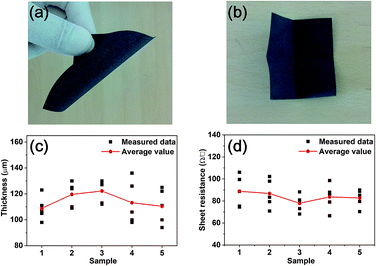
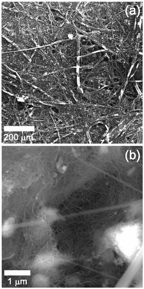
As a first step, we prepared a paper electrode including MWCNTs by the method described in ref. 41. As seen in Fig. 2(a), the color of the paper electrode is black, which means that MWCNTs were evenly composited with the cellulose from waste paper in spite of the absence of a dispersion agent. Moreover, the paper electrode is flexible and even freely foldable as displayed in Fig. 2(a) and (b) without losing the basic properties of paper itself. As explained above, the paper electrode plays a role of a cathode as well as a reservoir to contain the electrolyte. Thus, keeping the basic properties of paper such as being foldable and wettable has the merit in fabricating a foldable battery. Five sheets of paper were prepared to assure the reproducibility of thickness and sheet resistance. The measurement was conducted at five different sites of each sheet of paper. Fig. 2(c) represents the thickness measured from the five sheets of paper. The black closed square indicates measured data while the red closed circle displays the average value of the measurements. The averages are approximately distributed between 100 and 130 μm, meaning that the preparation method of the electrode is fairly reproducible. The same trend appears in the sheet resistance of the paper electrode as shown in Fig. 2(d). The average values of the sheet resistance of the electrode are ranging between 80 and 100 Ω □−1, implying that the paper electrode is quite electrically conductive in spite of the addition of 10 wt% of MWCNTs. In general, the electrical conductivity of a composite material is determined by the degree of percolation when carbon nanotube (CNT) is added as a conductive material. In other words, it can be understood that the superior conductivity of a composite originated from networks where individual MWCNTs are totally connected.To confirm this, SEM analysis was performed on the surface of the paper electrode. Fig. 3 shows SEM images obtained at low and high magnification enough to show CNTs in the composite. Fig. 3(a) clearly represents the image of a tangled structure of cellulose. This result is in good agreement with previous works reporting the images of the surface of paper or conductive paper to which CNT or carbon fiber was added for electrical conductivity.41–49 Fig. 3(b) exhibits the SEM image observed from the surface of cellulose in the paper electrode. The image apparently shows that MWCNTs are present on the surface as a structure of tangled networks. The connected MWCNTs are not only a good path for electrons, but also work as a catalyst for ORR. It is obvious that the networked structure contributed to the electrical conductivity of the paper electrode, leading to relatively low sheet resistance.
To investigate whether the paper electrode has electrocatalytic activity toward ORR, cyclic voltammetry measurement was carried out in N2- and O2-saturated conditions as shown in Fig. 4. As a result, it has been revealed that ORR occurred around the potential of −0.2 V with respect to an Ag/AgCl electrode. This result is comparable with a previous study40 investigating the electrocatalytic activity of MWCNTs toward ORR. The study reported that the oxygen reduction onset potential of MWCNTs was −0.083 V with respect to the saturated calomel electrode. Our result indicates that the paper electrode including 10 wt% of MWCNTs can work as a cathode for ORR sufficiently although there exists a little difference in the onset potential, compared with MWCNTs.
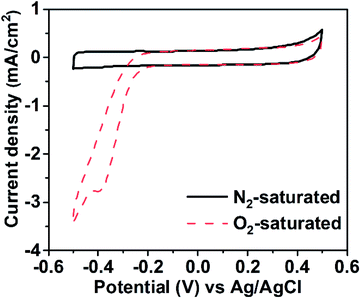 | ||
| Fig. 4 Cyclic voltammetry curves of the paper cathode in (black solid line) N2- and (red dashed line) O2-saturated 0.1 M KOH solution. | ||
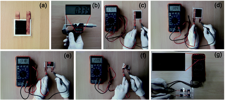
Fig. 5 shows photo images of the assembled reserve batteries in normal and deformed shapes. Fig. 5(a) displays a single cell of the reserve battery in an inactivated state. The paper electrode and the aluminum sheet were cut into squares of 6 cm on each side. The assembled battery resulted in a thickness of 335 μm as exhibited in Fig. 5(b). It is because the thickness of all parts is in the range less than 120 μm (paper electrode: avg. 110 μm, aluminum sheet: avg. 17 μm, separator: avg. 76 μm). This thickness can be controlled by changing each part to thinner or thicker one. Fig. 5(c) presents the reserve battery activated by injecting seawater. The output voltage of 0.7 V was measured immediately as soon as seawater permeated the paper electrode and the separator after injection. The discharge performance of the reserve battery activated by seawater will be discussed later. When the battery was activated by the KOH solution, the voltage increased up to 1.3 V as shown in Fig. 5(d), which is enough to trigger a desk clock (see the ESI Movie 1†). These results clarify that different voltages are generated by injecting a dissimilar solution. To investigate the deforming effect on the voltage, the battery activated by the KOH solution was folded and clipped as seen in Fig. 5(e). Interestingly, we can see that the voltage is not drastically changed, compared with the battery activated by the same solution in an unfolded state. Then, the battery was severely crumpled to see how the voltage changes under harsh conditions. Fig. 5(f) represents that the battery can be crumpled successfully like paper, and the voltage generated from the cell was measured to be 1.2 V which is a close value to the ones obtained from unfolded and folded batteries. The severely crumpled reserve battery also triggered the desk clock (see the ESI Movie 2†). It seems that crumpling battery does not influence the performance of the reserve battery significantly. Furthermore, the battery triggered the desk clock underwater for 1.75 h despite the fact that the system is fully open to water (see the ESI Movie 3†). Fig. 5(g) shows an exemplary application of our battery system where four cells are connected in series and packed into a single cell via a lamination pouch by using a transparent laminator. In this case, the paper electrode and the aluminum were cut into squares of 3 cm. The battery was activated by injecting the KOH solution through holes created in the transparent pouch and generated a voltage of 5.2 V. Considering that a single cell activated by the KOH solution generated a voltage of 1.3 V, this is a quite reasonable output voltage.
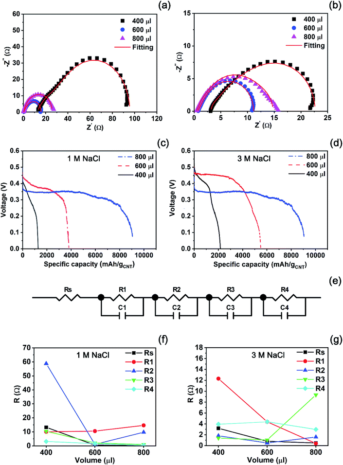
After preparing an empty cell, we should investigate how much an electrolyte is necessary for maximum discharge performance. For this, we observed a change in impedance spectra obtained from the reserve battery activated by different volumes of each solution. Fig. 6(a) and (b) show the impedance spectra measured from the batteries activated by the 1 M and 3 M NaCl solutions, respectively. In both cases, the volumes of 400, 600, and 800 μl were injected to an empty cell as an electrolyte. When 400 μl of the 1 M NaCl solution was used for activation, the largest semicircle was measured in the spectra. Then, the injection of 600 μl resulted in a relatively small semicircle, compared with 400 μl. When the volume of the electrolyte increased up to 800 μl, the semicircle became larger than the one recorded from the battery started by 600 μl of the 1 M NaCl solution. The diameter of the semicircle corresponds to a polarization resistance. Hence, a small semicircle implies that internal resistance becomes small and results in high cell performance. From this, we can expect that the injection of 600 μl will result in the highest performance among the experimental conditions. In the case of the 3 M NaCl solution, the same trend appeared as seen in Fig. 6(b). The smallest semicircle exhibited at the volume of 600 μl of the electrolyte while the largest one was recorded at the volume of 400 μl. The semicircle measured from the reserve battery activated by 800 μl was located between the largest and the smallest one. Therefore, the best performance is expected at the volume of 600 μl within the experimental range.
In order to confirm if the highest battery performance is obtained at the lowest impedance, we conducted a discharge test at a constant current of 3 mA after activating empty batteries by each volume of the electrolytes as presented in Fig. 6(c) and (d). When the 1 M NaCl solution activated the batteries, the specific capacity of each battery increased in proportion to the volume of the solution as plotted in Fig. 6(c). The 400 μl of the electrolyte resulted in 1278 mA h gCNT−1, and the specific capacity increased to 3806 mA h gCNT−1 at the injection volume of 600 μl. The highest specific capacity of 9057 mA h gCNT−1 was obtained at the volume of 800 μl. However, we can see a relatively low voltage during discharge in Fig. 6(c), compared with other two cases. The figure presents that the best performance in the aspect of output voltage exhibits when the battery is activated by 600 μl of the 1 M NaCl solution. In the case that the 3 M NaCl solution was used to activate batteries, this phenomenon becomes clear as seen in Fig. 6(d). We can see that the specific capacity increased from 2165 to 5489 mA h gCNT−1 as the injection volume changed from 400 to 600 μl. The injection volume of 800 μl to the reserve battery led to the specific capacity of 9057 mA h gCNT−1 which is greater than the value from the battery by 600 μl of the electrolyte. However, the output voltage during discharging was much lower than other voltages.
To examine why battery performance is influenced by the volumes of electrolytes, we found an equivalent circle model (ECM) fitting all impedance data plotted in Fig. 6(a) and (b). Fig. 6(e) presents the unique ECM comprised of both resistance and capacitance elements with solution resistance (Rs). All fitted parameter values were summarized in Table S1 (see the ESI†). In the case of the 1 M NaCl solution, most of resistance elements except R1 decrease as shown in Fig. 6(f) when the volume increases from 400 to 600 μl. As the volume of the electrolyte exceeds 600 μl, R1 and R2 increase at the volume of 800 μl. Therefore, it can be understood that the injection of 800 μl of the 1 M NaCl solution increased the internal resistance, resulting in a low output voltage. Fig. 6(g) reveals that the same trend is seen at high concentration of the 3 M NaCl solution. Most of resistance elements such as Rs, R1, R2, and R3 decrease when the injection volume increases from 400 to 600 μl. Then, the resistance elements of R3 increase abruptly at the volume of 800 μl. From these results, it can be interpreted that although the excess volume of the electrolyte results in high specific capacity, the increase in resistance values leads to low voltage during discharge irrespective of concentration.
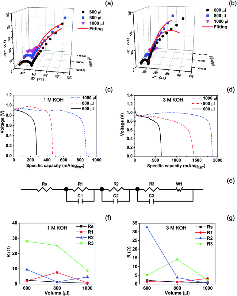
Fig. 5 showed that the KOH solution generated a higher voltage than the NaCl solution. Based on this preliminary result, we prepared each of 1 M and 3 M KOH solutions to see how the discharge performance of the battery varies with concentration at a high voltage. Before a discharge test, we also conducted impedance analysis to determine the optimal amount of the KOH solution which leads to the lowest impedance in the experimental conditions. Fig. 7(a) and (b) show impedance spectra measured from the batteries activated by each of 1 M and 3 M KOH solutions, respectively. In the case of the 1 M solution, a semicircle becomes small gradually as the injection volume increases from 600 to 1000 μl. Finally, the smallest semicircle appears at the volume of 1000 μl as seen in Fig. 7(a). Also, Fig. 7(b) presents that the batteries activated by 600, 800, and 1000 μl of the 3 M KOH solution exhibit the smallest semicircle at the volume of 1000 μl, which is similar with the case of the 1 M KOH solution.
Also, a discharge test of the batteries activated by the KOH solution was carried out at a constant current of 3 mA as seen in Fig. 7(c) and (d). We can see that a high voltage is generated in the discharge test, compared with the activated ones by NaCl solutions. When the battery was activated by the 1 M KOH solution, the specific capacity of the battery increased in proportion to the injected volume. 600 μl of the 1 M KOH solution resulted in the specific capacity of 275 mA h gCNT−1. Then, it finally approached 874 mA h g−1CNT at the volume of 1000 μl, which is consistent with the impedance analysis. That is, the smallest semicircle ensures the highest discharging performance originated from the optimal volume of the electrolyte. When the concentration increased to 3 M, the injection of 600 and 800 μl to reserve batteries resulted in the specific capacity values of 640 and 1421 mA h gCNT−1 as shown in Fig. 7(d). Then, the highest specific capacity of 1867 mA h gCNT−1 was achieved at the volume of 1000 μl which is the end point in the experimental range.
For further analysis, we investigated the unique ECM as seen in Fig. 7(e) which fits all impedance data plotted in Fig. 7(a) and (b). Fitted parameters were summarized in Table S2.† When the battery is activated by the 1 M KOH solution, most of resistance elements except R2 decrease at the volume of 1000 μl as plotted in Fig. 7(f). However, the R2 element did not show a rapid change at each volume, implying that the increase of an internal resistance by R2 does not influence the discharge performance at the volume of 1000 μl. As the concentration of the electrolyte rises to 3 M, the highest discharge performance exhibited at the volume of 1000 μl in the experimental range. In Fig. 7(g), resistance elements except R1 decrease when the injection volume increases from 600 to 1000 μl. However, the variation in the element of R1 is not remarkable in the experimental range, compared with other resistance elements. Therefore, it can be interpreted that in the case of KOH solution, the increase of resistance element is not influential to the discharge performance of a reserve battery at the volume of 1000 μl.
As shown in Fig. 5(c), the reserve battery was easily activated by seawater, resulting in approximately 0.7 V. To examine whether seawater can generate electricity as much as other electrolytes do, we carried out a discharge test under the same condition. 600 μl of seawater shipped from East Sea was injected into an inactivated reserve battery without any treatment. As a result, a nice discharging curve was obtained and specific capacity approached 8389 mA h gCNT−1 as seen in Fig. S1 (see the ESI†). This value is quite comparable with the results of reserve batteries activated by the 1 M and 3 M NaCl solutions, implying that empty cells of reserve batteries can be used in the ocean for the purpose of emergency rescue.
In order to study if folding reserve batteries influences the discharge performance, the batteries activated by 700 μl of 1 M NaCl were discharged at a constant current of 3 mA as seen in Fig. 8(a). It seems that the folding effect did not degrade the battery performance significantly, compared with an unfolded battery activated and discharged under the same experimental conditions. We can see that the folded battery rather performs better than the unfolded one in the aspect of the voltage during discharge. The reason can be also understood by examining the impedance spectra measured in folded and unfolded states. Fig. 8(b) presents that the battery in a folded state exhibits a relatively small semicircle in impedance analysis, meaning that the effect of folding a battery in not influential to discharge performance. The parameters estimated by using the ECM in Fig. 6(e) were summarized in Table S3 (see the ESI†). These results strongly show that it is possible to fabricate a battery which is freely transformed without any degradation in the battery performance.
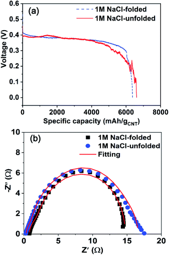 | ||
| Fig. 8 (a) Discharge performance at a constant rate of 3 mA and (b) impedance spectra of unfolded and folded batteries activated by the 1 M NaCl solution. | ||
4. Conclusions
In summary, we demonstrated a way of fabricating the extremely thin and foldable reserve battery which can be activated by not only the KOH and NaCl solutions, but also seawater. The paper electrode composed of MWCNTs and cellulose played as a role of a cathode for ORR and a reservoir to preserve the injected electrolytes, enabling the battery to be folded and crumpled severely. The empty cell generated different voltages, depending on the type of the injected solution. The injection of the KOH solution resulted in a relatively high voltage of 1.3 V while the battery initiated by the NaCl solution led to 0.7 V. Impedance analysis pointed out that the internal resistance of the reserve battery were influenced by the amount of the injected solution. Consequently, the best discharge performance was achieved at the volume of electrolytes leading to the lowest impedance. Unfolded and folded batteries exhibited almost same semicircle in impedance analysis, supporting that folding battery did not degrade the discharge performance.The novel battery system suggested here can be extended to other metal–air batteries for the purpose of both flexibility and foldability.
Conflicts of interest
There are no conflicts to declare.Acknowledgements
This research was supported by Basic Science Research Program through the National Research Foundation of Korea (NRF) funded by the Ministry of Education (2018R1D1A1B07049435) and also partially supported by Nano-Material Technology Development Program through the National Research Foundation of Korea (NRF) funded by Ministry of Science and ICT (NRF-2017M3A7B4049119).Notes and references
- T.-H. Han, Y. Lee, M.-R. Choi, S.-H. Woo, S.-H. Bae, B. H. Hong, J.-H. Ahn and T.-W. Lee, Nat. Photonics, 2012, 6, 105–110 CrossRef CAS.
- S. J. Park, O. S. Kwon, S. H. Lee, H. S. Song, T. H. Park and J. Jang, Nano Lett., 2012, 12, 5082–5090 CrossRef CAS PubMed.
- B. Tian, T. Cohen-Karni, Q. Qing, X. Duan, P. Xie and C. M. Lieber, Science, 2010, 329, 830–834 CrossRef CAS PubMed.
- S. Kim, H.-J. Kwon, S. Lee, H. Shim, Y. Chun, W. Choi, J. Kwack, D. Han, M. Song, S. Kim, S. Mohammadi, I. Kee and S. Y. Lee, Adv. Mater., 2011, 23, 3511–3516 CrossRef CAS PubMed.
- Y.-H. Lee, J.-S. Kim, J. Noh, I. Lee, H. J. Kim, S. Choi, J. Seo, S. Jeon, T.-S. Kim, J.-Y. Lee and J. W. Choi, Nano Lett., 2013, 13, 5753–5761 CrossRef CAS PubMed.
- J. Ren, Y. Zhang, W. Bai, X. Chen, Z. Zhang, X. Fang, W. Weng, Y. Wang and H. Peng, Angew. Chem., Int. Ed., 2014, 53, 7864–7869 CrossRef CAS PubMed.
- J. J. Park, W. J. Hyun, S. C. Mun, Y. T. Park and O. O. Park, ACS Appl. Mater. Interfaces, 2015, 7, 6317–6324 CrossRef CAS PubMed.
- Y. Wang, L. Wang, T. Yang, X. Li, X. Zang, M. Zhu, K. Wang, D. Wu and H. Zhu, Adv. Funct. Mater., 2014, 24, 4666–4670 CrossRef CAS.
- W. N. Carson, N. Y. Schenectady and W. H. Fischer, Sea water-activated primary battery, US Pat. 3352718, Nov. 14, 1967.
- J. B. Mullen and P. L. Howard, J. Electrochem. Soc., 1946, 90, 529–544 CrossRef.
- F. Sammoura, K. B. Lee and L. Lin, Sens. Actuators, A, 2004, 111, 79–86 CrossRef CAS.
- W. G. Darland and M. T. Ross, Gas-depolarized battery, US Pat. 2914595, Nov. 24, 1959.
- M. R. Hatfield, Heavy duty gas depolarized dry battery, US Pat. 2615931, Oct. 28, 1952.
- R. E. Johnson, W. G. Darland, C. A. Grulke, N. C. Cahoon and H. F. Schaefer, Gas-activated primary cells, US Pat. 2948767, Aug. 9, 1960.
- Y. Hu, H. Li, X. Huang and L. Chen, Electrochem. Commun., 2004, 6, 28–32 CrossRef CAS.
- R. T. Carlin, H. C. D. Long, J. Fuller and P. C. Trulove, J. Electrochem. Soc., 1994, 141, L73–L76 CrossRef CAS.
- B. Garcia, S. Lavallee, G. Perron, C. Michot and M. Armand, Electrochim. Acta, 2004, 49, 4583–4588 CrossRef CAS.
- K. Vuorilehto, J. Appl. Electrochem., 2003, 33, 15–21 CrossRef CAS.
- L. Wen, K. Yu, H. Xiong, Y. Dai, S. Yang, X. Qiao, F. Teng and S. Fan, Electrochim. Acta, 2016, 194, 40–51 CrossRef CAS.
- J. Zhao, K. Yu, Y. Hu, S. Li, X. Tan, F. Chen and Z. Yu, Electrochim. Acta, 2011, 56, 8224–8231 CrossRef CAS.
- R. Renuka, Mater. Chem. Phys., 1999, 59, 42–48 CrossRef CAS.
- Y. Shi, C. Peng, Y. Feng, R. Wang and N. Wang, Mater. Des., 2017, 124, 24–33 CrossRef CAS.
- K. Yu, X. Tan, Y. Hu, F. Chen and S. Li, Corros. Sci., 2011, 53, 2035–2040 CrossRef CAS.
- D. Linden and T. B. Reddy, Reserve batteries, Handbook of Batteries, McGraw-Hill, 2001, 3rd edn, p. 16.3 Search PubMed.
- H. Li, C. Han, Y. Huang, Y. Huang, M. Zhu, Z. Pei, Q. Xue, Z. Wang, Z. Liu, Z. Tang, Y. Wang, F. Kang, B. Li and C. Zhi, Energy Environ. Sci., 2018, 11, 941–951 RSC.
- M. Koo, K.-I. Park, S. H. Lee, M. Suh, D. Y. Jeon, J. W. Choi, K. Kang and K. J. Lee, Nano Lett., 2012, 12, 4810–4816 CrossRef CAS PubMed.
- N. Li, Z. Chen, W. Ren, F. Li and H.-M. Cheng, Proc. Natl. Acad. Sci., 2012, 109, 17360–17365 CrossRef CAS PubMed.
- Y. Huang, J. Liu, J. Zhang, S. Jin, Y. Jiang, S. Zhang, Z. Li, C. Zhi, G. Due and H. Zhou, RSC Adv., 2019, 9, 16313–16319 RSC.
- M. Kammoun, S. Berg and H. Ardebili, Nanoscale, 2015, 7, 17516–17522 RSC.
- Q. Li and H. Ardebili, J. Power Sources, 2016, 303, 17–21 CrossRef CAS.
- Y. Li, D. Ye, B. Shi, W. Liu, R. Guo, H. Pei and J. Xie, Phys. Chem. Chem. Phys., 2017, 19, 7498–7505 RSC.
- J. Ma, C. Qin, Y. Li, F. Ren, Y. Liu and G. Wang, J. Power Sources, 2019, 430, 244–251 CrossRef CAS.
- Y.-J. Wang, B. Fang, D. Zhang, A. Li, D. P. Wilkinson, A. Ignaszak, L. Zhang and J. Zhang, Electrochem. Energy Rev., 2018, 1, 1–34 CrossRef CAS.
- Md. A. Rahman, X. Wang and C. Wen, J. Electrochem. Soc., 2013, 160, A1759–A1771 CrossRef CAS.
- Y. Li, W. Xia, R. Zou, J. Zhang, Z. Chen and Q. Xu, RSC Adv., 2015, 5, 96580–96586 RSC.
- X. Wu, Z. Liu, Y. Jiang, J. Zeng and S. Liao, J. Mater. Sci., 2017, 52, 8432–8443 CrossRef CAS.
- H.-J. Zhang, H. Li, X. Li, B. Zhao and J. Yang, Int. J. Hydrogen Energy, 2014, 39, 16964–16975 CrossRef CAS.
- L. Osmieri, A. H. A. M. Videla and S. Specchia, J. Power Sources, 2015, 278, 296–307 CrossRef CAS.
- Z. Wang, H. Lei, R. Cao and M. Zhang, Electrochim. Acta, 2015, 171, 81–88 CrossRef CAS.
- H.-J. Zhang, H. Li, C. Deng, B. Zhao and J. Yang, ECS Electrochem. Lett., 2015, 4, H33–H37 CrossRef CAS.
- D.-H. Kim, Y.-I. Cho, J. H. Choi, H.-S. Kim, H. C. Shin, T. S. Lee, J. W. Jung, H.-D. Kim, D.-J. Lee and G. T. Kim, RSC Adv., 2015, 5, 32118–32123 RSC.
- M. Imai, K. Akiyama, T. Tanaka and E. Sano, Compos. Sci. Technol., 2010, 70, 1564–1570 CrossRef CAS.
- L. Jabbour, D. Chaussy, B. Eyraud and D. Beneventi, Compos. Sci. Technol., 2012, 72, 616–623 CrossRef CAS.
- B. Fugetsu, E. Sano, M. Sunada, Y. Sambongi, T. Shibuya, X. Wang and T. Hiraki, Carbon, 2008, 46, 1256–1258 CrossRef CAS.
- M. Salajkova, L. Valentini, Q. Zhou and L. A. Berglund, Compos. Sci. Technol., 2013, 87, 103–110 CrossRef CAS.
- L. Hu, J. W. Choi, Y. Yang, S. Jeong, F. L. Mantia, L.-F. Cui and Y. Cui, Proc. Natl. Acad. Sci. U.S.A., 2009, 106, 21490–21494 CrossRef CAS PubMed.
- S. H. Yoon, H.-J. Jin, M.-C. Kook and Y. R. Pyun, Biomacromolecules, 2006, 7, 1280–1284 CrossRef CAS PubMed.
- M. Agarwal, Q. Xing, B. S. Shim, N. Kotov, K. Varahramyan and Y. Lvov, Nanotechnology, 2009, 20, 215602 CrossRef PubMed.
- L. Hu, M. Pasta, F. L. Mantia, L. Cui, S. Jeong, H. D. Deshazer, J. W. Choi, S. M. Han and Y. Cui, Nano Lett., 2010, 10, 708–714 CrossRef CAS PubMed.
Footnote |
| † Electronic supplementary information (ESI) available. See DOI: 10.1039/c9ra09401f |
| This journal is © The Royal Society of Chemistry 2020 |

