 Open Access Article
Lychee-like TiO2@TiN dual-function composite material for lithium–sulfur batteries†
Wei Xu ,
Huimei Pang,
Heliang Zhou,
Zhixu Jian,
Riming Hu,
Yalan Xing* and
Shichao Zhang
 *
*
School of Materials Science and Engineering, Beihang University, Beijing 100191, P. R. China. E-mail: csc@buaa.edu.cn; Fax: +861082338148; Tel: +861082339319
First published on 15th January 2020
Abstract
Lithium–sulfur (Li–S) batteries are promising candidates for next generation rechargeable batteries because of their high energy density of 2600 W h kg−1. However, the insulating nature of sulfur and Li2S, the “shuttle effect” of lithium polysulfides (LiPSs), and the volumetric change of sulfur electrodes limit the practical application of Li–S batteries. Here, lychee-like TiO2@TiN hollow spheres (LTTHS) have been developed that combine the advantages of high adsorption TiO2 and high conductivity TiN to achieve smooth adsorption/spread/conversion of LiPSs and use them as a sulfur host material in Li–S batteries for the first time. The cathode exhibits an initial specific capacity of 1254 mA h g−1 and a reversible capacity of 533 mA h g−1 after 500 cycles at 0.2C, which corresponds to an average coulombic efficiency up to 99%. The cell with the LTTHS@S cathode achieved an extended lifespan of over 1000 cycles. Such good performance can be assigned to the good adsorption and catalysis of the dual-function TiO2@TiN composite. This work proved that the TiO2@TiN composite can be an attractive matrix for sulfur cathodes.
1. Introduction
Based on their outstanding energy density of 2500 W h kg−1, low cost, and environmental friendliness, lithium–sulfur (Li–S) batteries have potential in next generation battery systems.1–3 However, there are limitations that need to be addressed: (1) insufficient conductivity of sulfur as an electrode (10–30 S cm−1) causes decreased battery performance and requires the utilization of conductive host materials. (2) The shuttle effect of polysulfides (LiPSs, Li2Sn, 4 ≤ n ≤ 8) produced by the electrode reaction reduces the battery capacity. (3) The volume of the sulfur electrode varies greatly (∼80%) during the reaction process [S (2.03 g cm−3) and Li2S (1.66 g cm−3)].4–7 Each of these lead to low coulombic efficiency (CE), severe capacity fading, and short lifespan of Li–S batteries. To address the aforementioned challenges, plenty of approaches have been developed over the past decades: (1) host material preparation with high conductivity, such as porous carbons,8,9 carbon nanotubes,10 graphene sheets,11–14 conductive polymers,15–17 and metal-based compounds;18,19 (2) polar material introduction in the cathode to reduce sulfur loss by adsorption, such as TiO2,20 V2O5,19 MoO3,21 MnO2,22 and Co9S8;23 (3) separator modification to adsorb and transform the polysulfides.24 Recently, researchers have become focused on dual functional materials that show good electrical conductivity but also possess an excellent adsorption ability and transformation for polysulfides. Cui et al. fabricated a TiO2@S yolk–shell nanoarchitecture with 70 wt% sulfur content by coating the sulfur nanoparticles with TiO2 to form TiO2@S core–shell nanoparticles followed by partial sulfur removal to create empty space inside the TiO2 shell. It reached an initial discharge specific capacity of 1030 mA h g−1 at 0.5C and achieved a reversible capacity of over 600 mA h g−1 after 1000 cycles.20 However, the poor conductivity of TiO2 and, eventually, a hindered electron transport path, resulted in low sulfur utilization and energy density. In addition, Kim et al. proved that TiN possesses high adsorption for LiPSs.25 Ding et al. prepared a C@TiN@S electrode that exhibited an initial discharge specific capacity of 1309 mA h g−1 at 0.2C.26 Goodenough et al. confirmed the TiN-enhanced cycling performance of Li–S batteries.27 The above research proves that TiN possesses several advantages as sulfur hosts for Li–S batteries including: (1) outstanding chemical adsorption, (2) high electronic conductivity (higher than carbon and TiO2), and (3) excellent catalytic performance for LiPSs. Yang et al. designed a TiO2–TiN material coated on the commercial separator to obtain a modified separator, which enabled the battery to maintain 73% capacity after 2000 cycles.28 Inspired by the synergistic effect obtained from the TiO2–TiN composite, a dual-function TiO2@TiN composite was designed and prepared as the sulfur host, which showed better performance than either TiN@S or C@S.In this work, a dual functional composite material based on lychee-like TiO2@TiN hollow spheres (LTTHS) was prepared, which combined the advantages of high adsorption TiO2 and high conductivity TiN. A smooth adsorption/spread/conversion of LiPSs can be achieved with this composite. LTTHS was used as the sulfur host material in the Li–S battery for the first time, verifying the feasibility of the TiO2@TiN composite as a host material for advanced Li–S batteries. Designing fast adsorption/spread/conversion of LiPSs on host materials can efficiently reduce the shuttling effect of polysulfides, resulting in improved stability of the batteries. TiO2 played a critical role on chemical adsorption to LiPSs,29–31 and TiN possesses extremely good conductivity (4000–55![[thin space (1/6-em)]](https://www.rsc.org/images/entities/char_2009.gif) 000 S cm−1), as well as catalytic performance.27,32 The advantages of both materials were integrated and used to prepare hollow materials to provide buffer space for the volumetric expansion of sulfur during the electrode reaction. The initial capacity of the prepared battery was as high as 1254 mA h g−1 with an average coulombic efficiency of 99%. A high capacity of 533 mA h g−1 can be maintained after 500 cycles, which fully verifies the practicality of the TiO2@TiN composite material in the cathode of lithium–sulfur batteries and provides a new way and direction for the research of Li–S batteries.
000 S cm−1), as well as catalytic performance.27,32 The advantages of both materials were integrated and used to prepare hollow materials to provide buffer space for the volumetric expansion of sulfur during the electrode reaction. The initial capacity of the prepared battery was as high as 1254 mA h g−1 with an average coulombic efficiency of 99%. A high capacity of 533 mA h g−1 can be maintained after 500 cycles, which fully verifies the practicality of the TiO2@TiN composite material in the cathode of lithium–sulfur batteries and provides a new way and direction for the research of Li–S batteries.
2. Experimental
2.1 Synthesis of the precursor to lychee-like TiO2 spheres
The experiment method has referred to the work of Detlef W. Bahnemann et al.33 NH3·H2O (28%, 0.4 g) and H2O (1 g) were dissolved in a mixed solution of ethanol and acetonitrile in a volumetric ratio of 6![[thin space (1/6-em)]](https://www.rsc.org/images/entities/char_2009.gif) :
:![[thin space (1/6-em)]](https://www.rsc.org/images/entities/char_2009.gif) 4 (250 mL). Titanium isopropoxide (TTIP) (6 mL) was added into the solution under vigorous stirring, and the emulsion suspension was formed in 5 seconds. After stirring for 5 h, the mixture was centrifuged and washed with ethanol and deionized water twice, respectively.
4 (250 mL). Titanium isopropoxide (TTIP) (6 mL) was added into the solution under vigorous stirring, and the emulsion suspension was formed in 5 seconds. After stirring for 5 h, the mixture was centrifuged and washed with ethanol and deionized water twice, respectively.
2.2 Synthesis of lychee-like TiO2 hollow spheres (LTHS)
The precursor prepared above and 0.1 g PEG were re-dispersed in 30 mL deionized water. The solution was stirred and ultrasonicated to fill the PEG into the pores of the precursor. Fluoride (NaF, KF, or NH4F) was dissolved into solution as an etching agent with an F/Ti molar ratio of 0.12. Subsequently, NaF (0.1 g) was added and the obtained solution was stirred for 1 h. Then with PVP (0.15 g) added, the solution was stirred for another 1 h. After that, the solution was transferred to a 45 mL hydrothermal reactor and heated at 110 °C for 4 h. The precipitate was collected and washed with dilute NaOH (1 mmol L−1) and water. Finally, LTHS was obtained by calcining at 360 °C for 2 h at a heating rate of 2 °C min−1 in a tubular reactor.2.3 Synthesis of lychee-like TiO2@TiN hollow spheres (LTTHS)
Lychee-like TiO2@TiN hollow spheres were fabricated via the following procedures.34–36 First, the LTHS were mixed with urea at a mass ratio of 1![[thin space (1/6-em)]](https://www.rsc.org/images/entities/char_2009.gif) :
:![[thin space (1/6-em)]](https://www.rsc.org/images/entities/char_2009.gif) 6 via grinding. Then the mixture was transferred into a porcelain boat wrapped with copper foil. After four small holes were made with tweezers on the copper foil, the porcelain boat was heated under N2 atmosphere in the following manner: room temperature to 300 °C, 4 °C min−1; 300 to 800 °C, 2 °C min−1; 800 to 900 °C, 1 °C min−1; and maintained at 900 °C for 1 h (Fig. S3†). Finally, TiO2@TiN hollow spheres were prepared. Lychee-like TiN hollow spheres were obtained by heated under NH3 atmosphere at the same temperature. Then TiO2@TiN@S (LTTHS@S)were obtained by mixing sulfur and TiO2@TiN at a weight ratio of 6
6 via grinding. Then the mixture was transferred into a porcelain boat wrapped with copper foil. After four small holes were made with tweezers on the copper foil, the porcelain boat was heated under N2 atmosphere in the following manner: room temperature to 300 °C, 4 °C min−1; 300 to 800 °C, 2 °C min−1; 800 to 900 °C, 1 °C min−1; and maintained at 900 °C for 1 h (Fig. S3†). Finally, TiO2@TiN hollow spheres were prepared. Lychee-like TiN hollow spheres were obtained by heated under NH3 atmosphere at the same temperature. Then TiO2@TiN@S (LTTHS@S)were obtained by mixing sulfur and TiO2@TiN at a weight ratio of 6![[thin space (1/6-em)]](https://www.rsc.org/images/entities/char_2009.gif) :
:![[thin space (1/6-em)]](https://www.rsc.org/images/entities/char_2009.gif) 4 and heating overnight at 155 °C.
4 and heating overnight at 155 °C.
2.4 Visualized lychee-like TiO2@TiN hollow spheres adsorption test
Li2S6 solution was fabricated according to a previously reported method.37 Li2S and sulfur were mixed in a molar ratio of 1![[thin space (1/6-em)]](https://www.rsc.org/images/entities/char_2009.gif) :
:![[thin space (1/6-em)]](https://www.rsc.org/images/entities/char_2009.gif) 5 in 1,3-dioxolane/1,2-dimethoxyethane (DOL/DME) to obtain a homogeneous solution of 0.01 M Li2S6. Then, 50 mg of LTTHS were placed into the 10 mL Li2S6/DME solution. The adsorption was observed after 24 h (Fig. S2†).
5 in 1,3-dioxolane/1,2-dimethoxyethane (DOL/DME) to obtain a homogeneous solution of 0.01 M Li2S6. Then, 50 mg of LTTHS were placed into the 10 mL Li2S6/DME solution. The adsorption was observed after 24 h (Fig. S2†).
2.5 Characterization
The particle morphology and size of the samples were characterized by field emission scanning election microscopy (FE-SEM, Hitachi S-4800) and transmission electron microscopy (TEM, JEM-2100 F). X-ray photoelectron spectroscopy (XPS) was used to analyze the surface species and their chemical states. X-ray diffraction (XRD) patterns were characterized by a Rigaku D/MAX 2500/PC diffractometer using Cu Kα radiation. The specific surface area, pore volume, and pore size distribution of the samples were characterized by a Brunauer–Emmett–Teller analyzer (BET). The sulfur content in the sample was quantitatively determined by thermogravimetric analysis. The test environment was at an argon atmosphere, and the room temperature was increased to 600 °C at a heating rate of 10 °C min−1.2.6 Electrochemical measurements
Electrodes were fabricated by mixing as-prepared sulfur-based composites, polyvinylidene fluoride (PVDF) binder, and carbon black at a weight ratio of 8![[thin space (1/6-em)]](https://www.rsc.org/images/entities/char_2009.gif) :
:![[thin space (1/6-em)]](https://www.rsc.org/images/entities/char_2009.gif) 1
1![[thin space (1/6-em)]](https://www.rsc.org/images/entities/char_2009.gif) :
:![[thin space (1/6-em)]](https://www.rsc.org/images/entities/char_2009.gif) 1 in N-methyl-2-pyrrolidone (NMP). The obtained slurry was then cast onto a coated aluminum foil current collector. Finally, the electrodes were obtained after vacuum drying at 50 °C for 24 h to remove NMP and rolled with a thickness around 20 μm (1 cm2 area, the active material loading: 1.8–2 mg cm−2). The as-obtained cathode, anodes (lithium foil), and the Celgard 2300 membrane as the separator were used to fabricate the electrochemical cell. CR-2032 coin cells were assembled in an argon-filled glove box. The electrolyte was 1 mol L−1 lithium bis(trifluoromethanesulfonyl)imide (LITFSI) in a mixed solution of DOL and DME (v/v = 1
1 in N-methyl-2-pyrrolidone (NMP). The obtained slurry was then cast onto a coated aluminum foil current collector. Finally, the electrodes were obtained after vacuum drying at 50 °C for 24 h to remove NMP and rolled with a thickness around 20 μm (1 cm2 area, the active material loading: 1.8–2 mg cm−2). The as-obtained cathode, anodes (lithium foil), and the Celgard 2300 membrane as the separator were used to fabricate the electrochemical cell. CR-2032 coin cells were assembled in an argon-filled glove box. The electrolyte was 1 mol L−1 lithium bis(trifluoromethanesulfonyl)imide (LITFSI) in a mixed solution of DOL and DME (v/v = 1![[thin space (1/6-em)]](https://www.rsc.org/images/entities/char_2009.gif) :
:![[thin space (1/6-em)]](https://www.rsc.org/images/entities/char_2009.gif) 1) with 0.2 M LiNO3 as the electrolyte additive. The cell stood for 12 hours before cycling to ensure that enough electrolyte penetrated the electrode. The cells were galvanostatically discharged and charge cycled on a LAND-CT2001A test system between 1.7 to 2.8 V versus Li/Li+. The cyclic voltammetry (CV) data were collected by a CHI 660D electrochemical workstation (0.1 mV s−1, 1.7–2.8 V vs. Li/Li+). Electrochemical impedance spectra (EIS) measurements were carried out in the scan frequency range of 100 kHz to 10 MHz with an amplitude of 5 mV.
1) with 0.2 M LiNO3 as the electrolyte additive. The cell stood for 12 hours before cycling to ensure that enough electrolyte penetrated the electrode. The cells were galvanostatically discharged and charge cycled on a LAND-CT2001A test system between 1.7 to 2.8 V versus Li/Li+. The cyclic voltammetry (CV) data were collected by a CHI 660D electrochemical workstation (0.1 mV s−1, 1.7–2.8 V vs. Li/Li+). Electrochemical impedance spectra (EIS) measurements were carried out in the scan frequency range of 100 kHz to 10 MHz with an amplitude of 5 mV.
3. Results and discussion
3.1 Morphological analysis
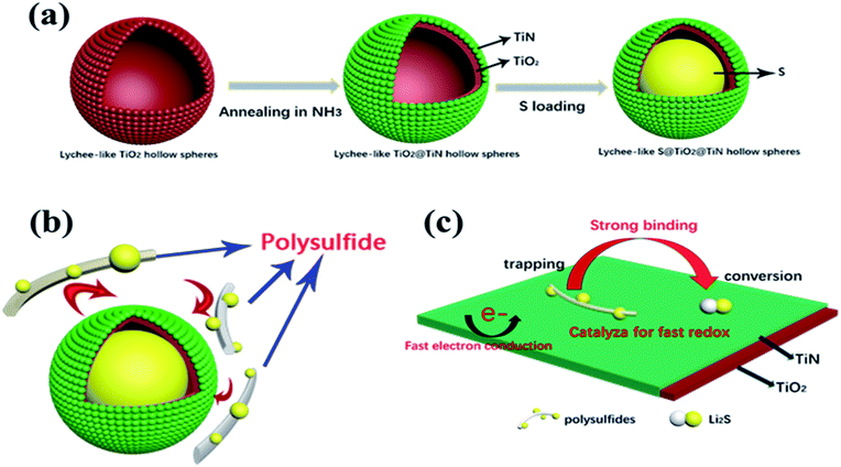
The entire synthetic procedure of Lychee-like S@TiO2@TiN composites is shown schematically in Fig. 1a. First, the precursor was prepared by precipitating TTIP in a mixed solution of ethanol and acetonitrile containing a small amount of H2O and NH3, wherein NH3 was used as a morphological controller. By mixing the as-prepared precursor with fluoride and then PVP, the lychee shape structure was formed. Subsequently, the mixed solution was hydrothermally reacted at 110 °C for 4 h to conduct the crystallization. As a result, the lychee-like TiO2 hollow spheres were obtained (Fig. 2a). Secondly, lychee-like TiO2 hollow spheres were mixed with urea, and then calcined at high temperature to obtain lychee-like TiO2@TiN hollow spheres (Fig. 2b). TiO2 and urea were mixed in a mass ratio of 1![[thin space (1/6-em)]](https://www.rsc.org/images/entities/char_2009.gif) :
:![[thin space (1/6-em)]](https://www.rsc.org/images/entities/char_2009.gif) 6 to ensure an insufficient reaction to obtain a TiO2@TiN mixture; the reaction process can be described as eqn (1).
6 to ensure an insufficient reaction to obtain a TiO2@TiN mixture; the reaction process can be described as eqn (1).| TiO2 + NH3 → TiN + N2↑ + H2O↑ | (1) |
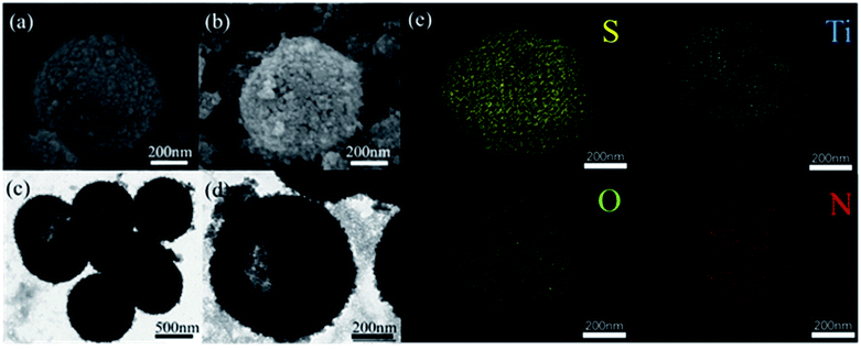 | ||
| Fig. 2 SEM images of LTHS (a) and LTTHS (b), TEM images of LTHS (c) and LTTHS (d), (e) EDX spectra of LTTHS@S. | ||
The morphology and size of the LTHS and LTTHS were investigated by scanning electron microscopy (SEM). As shown in Fig. 2 and S1,† the LTHS and LTTHS showed lychee-like morphology with a uniform diameter of ∼600 nm. The LTTHS retain their original morphology after reacting with ammonia at high temperature (Fig. 2a and b). SEM images of broken LTTHS reveal that the sample has a hollow morphology (Fig. S1†). Further demonstrated by the TEM, the image in Fig. 2d illustrates that LTTHS show a hollow lychee-like morphology, which is beneficial for sulfur loading and buffer volume expansion effect. SEM images reveal that the surface morphology of the LTTHS are generally maintained after calcination, except for a small increase (50 nm) in the thickness of the shell of the nanoparticles due to the substitution of two oxygen atoms with one nitrogen atom.38
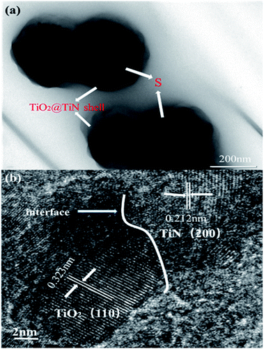
The outer TiN film can provide good conductivity and catalytic effect on polysulfide. The inner layer of TiO2 can anchor and chemically adsorb polysulfide. The entire adsorption process is shown in Fig. 1b. The hollow spherical structure can buffer the volume changes of the sulfur electrode during the electrode reaction. The reaction confined to the sphere effectively prevents polysulfide from escaping the sphere, where TiO2 is shown to possess an adsorption effect on polysulfides. Polysulfide is firmly confined near the positive electrode, and the LTTHS provide a stable framework for converting polysulfides and conducting electrons. TiN acts as a catalyst in the electrode reaction that promotes rapid conversion from Li2S4–8 to Li2S.28 The specific schematic diagram is shown in Fig. 1c, where the unique design of the LTTHS combines the advantages of the two polar materials, high adsorption TiO2 and high conductivity TiN. As shown in the illustration, the LiPSs anchored on the TiO2 layer rapidly diffuse to the outer TiN film and are transformed into Li2S. The unique lychee-like S@TiO2@TiN structure was confirmed by TEM (Fig. 3a) where the sulfur nanoparticles are encapsulated in the internal void space of the TiO2@TiN shells. Due to the two-dimensional imaging characteristics of the TEM image, the void space will appear as a blank area or a lower intensity area, depending on the shape of the particle. The high-magnification TEM image in Fig. 3b shows lattice fringes at 0.212 nm and 0.332 nm spacing, corresponding to the (200) plane of TiN and the (110) plane of rutile TiO2, respectively. As shown in Fig. 3b, TiN and TiO2 are twinborn together and a clear interface is observed between them. This interface can act as a site to adsorb LiPS and provide an electronic channel for rapid conversion.
3.2 Structural analysis
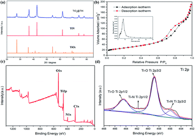
The XRD patterns of the lychee-like TiO2@TiN are shown in Fig. 4a. The characteristic peaks at 27.4°, 36°, 41.2°, and 54.3° can be attributed to the (110), (101), (111), and (211) crystal faces of rutile TiO2, while the peaks at 36.6°, 42.5°, 61.7°, 74°, and 77.9° can be designated as TiN (111), (200), (220), (311), and (222) planes. The corresponding XRD pattern confirms that the material contains both TiO2 and TiN phases. Energy dispersive X-ray (EDX) spectra provide information of elemental distribution in the lychee-like S@TiO2@TiN hollow spheres (LTTHS@S) (Fig. 2e). Ti, N, O, and S elements were evenly distributed on the surface, further manifesting the successful synthesis of lychee-like S@TiO2@TiN hollow spheres. XPS further proves the surface elemental and chemical states of the sample, as shown in Fig. 4c, which confirms the existence of O, Ti, and N elements. The XPS spectrum of Ti in the 2p region from the TiO2@TiN composite (Fig. 4d) was fitted into three peaks of Ti–O (464.7 eV), Ti–O (458.8 eV), Ti–N (460.9 eV) and Ti–N (455.8 eV), proving that the sample composition is a mixture of TiO2 and TiN. It should be emphasized that the analysis depth of XPS does not exceed 20 nm. This indicates that TiO2 was coated with a very thin layer of TiN, which will have a good effect on limiting diffusion of polysulfide.28 The N2 adsorption desorption isotherm is shown in Fig. 3b, indicating that the BET surface area of the LTTHS is 97.69 m2 g−1, and the pore volume of the LTTHS is 0.297 cm3 g−1. The pore size distribution curve shows that the average pore diameter of the LTTHS was 10 nm. The high specific surface area and large pore volume provide a macroporous structure to store sulfur, which afford more reactive sites for polysulfides, thereby significantly increasing the batteries' cycling stability. Thermogravimetric analysis (TGA) indicates that the sulfur content of LTTHS@Swas 65% (Fig. S4†). Due to the effective adsorption and rapid conversion of LTTHS to polysulfide, the yellow Li2S6/DME solution of LTTHS became colorless after 24 h (Fig. S2†).3.3 Electrochemical analysis
Fig. 5a shows the CV curves of the cells with LTTHS@S electrodes. Two typical reduction peaks were observed at 2.35 V and 2.06 V. The reduction peak at about 2.35 V indicates the reduction of S8 to Li2S4–8, and the reduction peak at about 2.06 V is related to the reduction of Li2S4–8 to Li2S2 and Li2S. During the anodic scans, the two oxidation peaks at 2.36 V and 2.38 V correspond to the oxidation of lithium sulfide to LiPS/S.39,40 The reduction peak of the LTTHS@S electrode at lower potential indicates the effective adsorption of LiPSs and the rapid conversion of the sulfur electrode. The sharper redox peaks of the LTTHS@S electrode indicate lower interface resistance and fast electron transfer, which is attributed to significant increases in conductivity.41 For the LTTHS@S electrode, the fifth CV cycle overlaps with the first one, demonstrating outstanding reversibility and stability of the LSTTHS electrode. As shown in Fig. S6,† during the oxidation scan, compared to LTHS@S, there is a significant negative shift in peak of the LTTHS@S, which indicates that LTTHS@S facilitates the transition from long-chain polysulfides to short-chain polysulfides. This result prove the catalysis effect of TiN.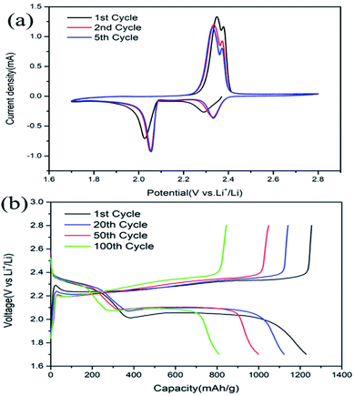 | ||
| Fig. 5 (a) CV profiles of LTTHS@S at a scan rate of 0.1 mV s−1. (b) Charge/discharge profiles of LTTHS@S at a rate of 0.2C. | ||
The galvanostatic discharge and charge (GDC) curves of LTTHS@S at 0.2C (1C = 1672 mA g−1) are presented in Fig. 5b. In the discharge and charge curves, two voltage platforms appeared at approximately 2.3 V and 2.1 V, which correspond to the results of the CV curves in Fig. 5a. After the first cycle, an increase in the discharge voltage platform also indicated a decrease in electrode polarization, which confirms the results of the CV and EIS discussed above.
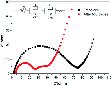
As shown in Fig. 6, the charge-transfer resistance (Rct) was greatly reduced after cycling. As the battery began to operate, the distribution of the sulfur electrode was uneven, resulting in a large resistance, but as the battery continued to work, the agglomerated sulfur was evenly distributed again, and the resistance decreased. As shown in Fig. S7,† The resistance of LTTHS@S is lower than LTHS@S. The electrochemical performance of LTTHS@S was evaluated using CR2032 coin cells. As shown in Fig. 7a, the LTTHS@S electrode delivers an initial discharge capacity of 1254 mA h g−1 and was retained at 871 mA h g−1 after 100 cycles, which is 69.4% of the first cycle (533 mA h g−1 after 500 cycles), which shows excellent electrochemical performance. Furthermore, as shown in Fig. S5,† LTTHS@S exhibited stable cycle performance in 1000 charge and discharge cycles of 0.2C (1C = 1672 mA g−1) (only 0.2% capacity attenuation per cycle). Most importantly, the calculated average coulombic efficiency over 1000 cycles was 97.3%, showing a slight shuttle effect due to the polysulfide limitation of the sample.
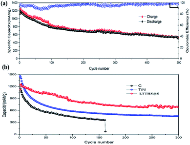 | ||
| Fig. 7 (a) Cycle performance and coulombic efficiency of LTTHS@S over 500 cycles at 0.2C. (b) Cycling performance of C–S, TiN–S, and LTTHS@S over 300 cycles at 0.2C. | ||
For comparison, batteries were assembled with conductive carbon black and TiN as the cathode materials, respectively (Fig. 7b). The initial discharge and charge capacities of the conductive carbon black and TiN electrodes were 1150 and 1480 mA h g−1, respectively. Owing to the extreme dissolution of soluble LiPSs, C@S electrodes only operated over 160 cycles with fast capacity attenuation. TiN electrodes also have rapid capacity decay due to the lack of chemisorption of polysulfides. However, as can be seen, the capacity retention of LTTHS@S (706 mA h g−1 after 300 cycles at 0.2C) was much higher than both C@S and TiN@S electrodes (460 mA h g−1 after 300 cycles at 0.2C). LTTHS@S exhibited excellent cycling stability owing to the strong chemical interaction of LTTHS@S and LiPSs to effectively prevent the shuttle effect. Furthermore, higher current rates were performed to confirm the outstanding high current cycle performance of LTTHS@S and LTHS@S electrode at 2C (Fig. 8a), respectively. LTTHS@S exhibits an initial discharge capacity of 823 mA h g−1, and after 200 cycles, the capacity of LTTHS@S was retained at 525 mA h g−1. On the contrary, LTHS@S exhibits an initial discharge capacity of 710 mA h g−1, and after 200 cycles, the capacity of LTHS@S was retained at 368 mA h g−1. Namely, LTTHS@S electrode can significantly restrain the shuttle effect of polysulfide and improve the electrochemical performance. In addition, the LTTHS@S electrode was subject to cycling at different current densities from 0.2 to 2C to evaluate their rate capabilities (Fig. 8b). The discharge capacities of LTTHS@S were 931, 711, 580, 465, and 681 mA h g−1, respectively, further confirming excellent rate performance, cycling stability, and high reversibility of the electrode. Thus, this work provides innovative avenues for Li–S batteries.
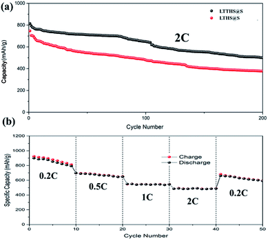 | ||
| Fig. 8 (a) Cycle performance of LTTHS@S and LTHS@S over 200 cycles at 2C. (b) Rate performance at different current densities of LTTHS@S. | ||
4. Conclusion
In summary, an easy and unique method was developed to synthesize dual functional lychee-like TiO2@TiN hollow spheres used as sulfur host materials to achieve smooth adsorption/spread/conversion of LiPSs for Li–S batteries. For the first time, it has been confirmed that the TiO2@TiN composite was used as the host material for lithium–sulfur batteries. The LTTHS@S show a hollow structure, which means the presence of the internal void space buffers the volume change of the sulfur electrode during the electrode reaction. Moreover, it is known that the hydrophilic Ti–O group and the surface hydroxyl group of TiO2 can be bonded to LiPS, hence further restraining the degree of dissolution of LiPS, which can greatly decrease the “shuttle effect”.40 On the other hand, the good electrical conductivity of TiN also plays a critical catalytic role in promoting the electrode reaction process. Benefiting from strong adsorption characteristics, high conductivity, and fast catalytic performance of TiO2@TiN, the LTTHS@S electrode exhibits a high specific capacity of 1254 mA h g−1 at 0.2C, up to 1000 cycles of charge and discharge cycles, with a decay of only 0.2% per cycle. The high capacity and excellent cycle performance of the TiO2@TiN electrode can be attributed to the inhibition of polysulfide by the dual-function composite material. This research creates a promising avenue for high performance Li–S batteries.Conflicts of interest
There are no conflicts to declare.Acknowledgements
This work was supported by National Natural Science Foundation of China (51774017 and 51575030) and Key Program of Equipment Pre-Research Foundation of China (6140721020103).Notes and references
- R. Chen, T. Zhao, J. Lu, F. Wu, L. Li, J. Chen, G. Tan, Y. Ye and K. Amine, Nano Lett., 2013, 13, 4642–4649 CrossRef CAS PubMed.
- D.-W. Wang, Q. Zeng, G. Zhou, L. Yin, F. Li, H.-M. Cheng, I. R. Gentle and G. Q. M. Lu, J. Mater. Chem. A, 2013, 1, 9382 RSC.
- N. Zhang, B. Li, S. Li and S. Yang, Adv. Energy Mater., 2018, 8, 1703124 CrossRef.
- Z. P. Cano, D. Banham, S. Ye, A. Hintennach, J. Lu, M. Fowler and Z. Chen, Nat. Energy, 2018, 3, 279–289 CrossRef.
- Y. Song, W. Cai, L. Kong, J. Cai, Q. Zhang and J. Sun, Adv. Energy Mater., 2019, 1901075, DOI:10.1002/aenm.201901075.
- L. Fan, M. Li, X. Li, W. Xiao, Z. Chen and J. Lu, Joule, 2019, 3, 361–386 CrossRef CAS.
- Z. Li, Y. Zhou, Y. Wang and Y.-C. Lu, Adv. Energy Mater., 2019, 9, 1802207 CrossRef.
- X. Ji, K. T. Lee and L. F. Nazar, Nat. Mater., 2009, 8, 500–506 CrossRef CAS PubMed.
- H.-J. Peng, J.-Q. Huang, X.-B. Cheng and Q. Zhang, Adv. Energy Mater., 2017, 7, 1770141 CrossRef.
- R. Raccichini, A. Varzi, S. Passerini and B. Scrosati, Nat. Mater., 2015, 14, 271–279 CrossRef CAS PubMed.
- L. Yuan, H. Yuan, X. Qiu, L. Chen and W. Zhu, J. Power Sources, 2009, 189, 1141–1146 CrossRef CAS.
- S. W. Ma, D. L. Zhao, N. N. Yao and L. Xu, Adv. Mater. Res., 2014, 936, 369–373 Search PubMed.
- T. Lin, Y. Tang, Y. Wang, H. Bi, Z. Liu, F. Huang, X. Xie and M. Jiang, Energy Environ. Sci., 2013, 6, 1283 RSC.
- Q. Peng, F. Yu, W. Wang, A. Wang, F. Wang and Y. Huang, Electrochim. Acta, 2019, 299, 749–755 CrossRef CAS.
- H. Chen, W. Dong, J. Ge, C. Wang, X. Wu, W. Lu and L. Chen, Sci. Rep., 2013, 3, 1910 CrossRef PubMed.
- Z. Wang, Y. Chen, V. Battaglia and G. Liu, J. Mater. Res., 2014, 29, 1027–1033 CrossRef CAS.
- M. Yu, W. Yuan, C. Li, J.-D. Hong and G. Shi, J. Mater. Chem. A, 2014, 2, 7360 RSC.
- X. Liu, J. Q. Huang, Q. Zhang and L. Mai, Adv. Mater., 2017, 29, 1601759 CrossRef PubMed.
- W. Li, J. Hicks-Garner, J. Wang, J. Liu, A. F. Gross, E. Sherman, J. Graetz, J. J. Vajo and P. Liu, Chem. Mater., 2014, 26, 3403–3410 CrossRef CAS.
- Z. Wei Seh, W. Li, J. J. Cha, G. Zheng, Y. Yang, M. T. McDowell, P. C. Hsu and Y. Cui, Nat. Commun., 2013, 4, 1331 CrossRef PubMed.
- H. Ye, L. Ma, Y. Zhou, L. Wang, N. Han, F. Zhao, J. Deng, T. Wu, Y. Li and J. Lu, Proc. Natl. Acad. Sci. U. S. A., 2017, 114, 13091–13096 CrossRef CAS PubMed.
- S. Huang, L. Liu, Y. Wang, Y. Shang, L. Zhang, J. Wang, Y. Zheng, O. G. Schmidt and H. Y. Yang, J. Mater. Chem. A, 2019, 7, 6651–6658 RSC.
- C. Dai, J.-M. Lim, M. Wang, L. Hu, Y. Chen, Z. Chen, H. Chen, S.-J. Bao, B. Shen, Y. Li, G. Henkelman and M. Xu, Adv. Funct. Mater., 2018, 28, 1704443 CrossRef.
- Y. Li, W. Wang, X. Liu, E. Mao, M. Wang, G. Li, L. Fu, Z. Li, A. Y. S. Eng, Z. W. Seh and Y. Sun, Energy Storage Mater., 2019, 23, 261–268 CrossRef.
- T.-G. Jeong, D. S. Choi, H. Song, J. Choi, S.-A. Park, S. H. Oh, H. Kim, Y. Jung and Y.-T. Kim, ACS Energy Lett., 2017, 2, 327–333 CrossRef CAS.
- Y. Wang, R. Zhang, Y.-c. Pang, X. Chen, J. Lang, J. Xu, C. Xiao, H. Li, K. Xi and S. Ding, Energy Storage Mater., 2019, 16, 228–235 CrossRef.
- Z. Cui, C. Zu, W. Zhou, A. Manthiram and J. B. Goodenough, Adv. Mater., 2016, 28, 6926–6931 CrossRef CAS PubMed.
- T. Zhou, W. Lv, J. Li, G. Zhou, Y. Zhao, S. Fan, B. Liu, B. Li, F. Kang and Q.-H. Yang, Energy Environ. Sci., 2017, 10, 1694–1703 RSC.
- S. Evers, T. Yim and L. F. Nazar, J. Phys. Chem. C, 2012, 116, 19653–19658 CrossRef CAS.
- Q. Sun, K. Chen, Y. Liu, Y. Li and M. Wei, Chemistry, 2017, 23, 16312–16318 CrossRef CAS PubMed.
- Z. Xiao, Z. Yang, L. Wang, H. Nie, M. Zhong, Q. Lai, X. Xu, L. Zhang and S. Huang, Adv. Mater., 2015, 27, 2891–2898 CrossRef CAS PubMed.
- B. Qi, X. Zhao, S. Wang, K. Chen, Y. Wei, G. Chen, Y. Gao, D. Zhang, Z. Sun and F. Li, J. Mater. Chem. A, 2018, 6, 14359–14366 RSC.
- J. H. Pan, X. Z. Wang, Q. Huang, C. Shen, Z. Y. Koh, Q. Wang, A. Engel and D. W. Bahnemann, Adv. Funct. Mater., 2014, 24, 95–104 CrossRef CAS.
- S. Dong, X. Chen, L. Gu, X. Zhou, H. Xu, H. Wang, Z. Liu, P. Han, J. Yao, L. Wang, G. Cui and L. Chen, ACS Appl. Mater. Interfaces, 2011, 3, 93–98 CrossRef CAS PubMed.
- B. Mazumder and A. L. Hector, J. Mater. Chem., 2009, 19, 4673 RSC.
- Y.-S. Jun, W. H. Hong, M. Antonietti and A. Thomas, Adv. Mater., 2009, 21, 4270–4274 CrossRef CAS.
- Z. Jian, H. Li, R. Cao, H. Zhou, H. Xu, G. Zhao, Y. Xing and S. Zhang, Electrochim. Acta, 2019, 319, 359–365 CrossRef CAS.
- D.-R. Deng, T.-H. An, Y.-J. Li, Q.-H. Wu, M.-S. Zheng and Q.-F. Dong, J. Mater. Chem. A, 2016, 4, 16184–16190 RSC.
- X. Huang, Z. Wang, R. Knibbe, B. Luo, S. A. Ahad, D. Sun and L. Wang, Energy Technol., 2019, 7, 1801001 Search PubMed.
- A. Manthiram, Y. Fu, S. H. Chung, C. Zu and Y. S. Su, Chem. Rev., 2014, 114, 11751–11787 CrossRef CAS PubMed.
- J.-X. Lin, Y.-X. Mo, P.-F. Zhang, Y.-Y. Li, Y.-J. Wu, S.-J. Zhang, Z.-G. Gao, J.-D. Chen, W.-F. Ren, J.-T. Li, Y. Zhou, L. Huang and S.-G. Sun, Mater. Today Energy, 2019, 13, 267–276 CrossRef.
Footnote |
| † Electronic supplementary information (ESI) available. See DOI: 10.1039/c9ra09534a |
| This journal is © The Royal Society of Chemistry 2020 |

