 Open Access Article
Studies on durability of sustainable biobased composites: a review
Boon Peng Chang a,
Amar K. Mohanty
 *ab and
Manjusri Misra
 *ab
*ab
aBioproducts Discovery and Development Centre, Department of Plant Agriculture, Crop Science Building, University of Guelph, 50 Stone Road East, Guelph, Ontario N1G 2W1, Canada. E-mail: mohanty@uoguelph.ca; mmisra@uoguelph.ca
bSchool of Engineering, Thornbrough Building, University of Guelph, 50 Stone Road East, Guelph, Ontario N1G 2W1, Canada
First published on 13th May 2020
Abstract
Global concerns over environmental issues have led to a tremendous growth in sustainable materials emerging from biobased plastics and their composites (biocomposites). This class of materials can be an alternative to traditional composite materials to reduce the carbon footprint and strain on the environment. Many studies and reviews have been focused on enhancing the mechanical performance of biocomposites with the aim for them to compete with traditional composites and expand their applications. However, the current scientific knowledge relating to the long-term durability performance of biocomposites is very limited in open access literature. Studies of the effects of different aging mechanisms when subjected to different service conditions and environments on the biocomposites' behaviours are needed. This review provides a focused discussion on the overview of the long-term durability performance and degradation behaviour under various aging environments (thermo-oxidative aging, accelerated weathering (ultraviolet aging), hydrolytic degradation, fatigue and creep, etc.) of the commercially important biobased-composites for the first time. Future perspectives and methods to improve the durability performance of biocomposites are also discussed in this review.
1. Introduction
Traditional petroleum-based polymer composites have extensive use in a large number of diverse applications, ranging from small household devices to structural aircraft parts due to their high strength-to-weight ratios as compared to conventional materials. The intensive reliance of plastics has led to an increasing amount of plastic waste in the environment. As a result of the social and environmental awareness, there have been changes to industrial materials in recent years where manufacturers have started adopting “cradle-to-beyond the grave” approaches in their product design. With the depletion of petroleum resources and growing global environmental concerns over climate change and environmental pollution, the development of sustainable biobased materials have been growing at a fast pace. Countries including China, France, United Kingdom, Germany, the United States, Japan, and Canada have developed strategies to adapt the circular economy model through sustainable and efficient resource management to help reduce the environmental strain from waste.1–4 These countries reinforce these strategies by emphasizing rules and regulations placed on industry manufacturers to develop more sustainable and environmentally friendly products from biobased and biodegradable materials.5,6The research and development of new biobased and biodegradable polymers from renewable resources as alternatives to conventional plastics has become an enticing area for both academic and industrial research due to the global concerns over plastic waste and pollution issues. These pro-environmental materials could be a promising solution for the global plastic waste problem. As a result, global production of polymers (biodegradable or non-biodegradable) sourced from sustainable natural resources have increased over 400% from 2016 to 2019.7 Renewable polymers can be categorized into three groups: (a) natural polymers (e.g. thermoplastic starch (TPS), cellulose and protein, etc.), (b) synthetic polymers from natural biomass feedstocks (e.g. poly(lactic acid) (PLA) etc.), and (c) synthetic polymers from microbial fermentation (e.g. poly(hydroxy alkanoate) (PHA) such as poly(3-hydroxybutyrate-co-3-hydroxyvalerate) (PHBV)). Sustainable biodegradable polymers derived from sustainable feedstocks such as PLA, polysaccharides, poly(butylene succinate) (PBS), and PHAs are some of the successful and innovative polymers that have been developed to address these environmental issues. Biodegradable synthetic polymers sourced from petroleum feedstock, such as poly(butylene adipate-co-terephthalate) (PBAT) and poly(caprolactone) (PCL) for example, have also gained popularity in recent years even though they are not renewable. Many biobased polymers are under development with the aims to replace 100% petro-based plastics currently in use in the market. The production of large-scale partially biobased polyesters, such as bio-poly(ethylene terephthalate) (bio-PET), bio-poly(trimethylene terephthalate) (bio-PTT), and bio-poly(butylene terephthalate) (bio-PBT), have been implemented by a number of plastic production companies since 2010.8 However, the practical use of bioplastics in applications is still very limited due to high costs, limitations with small scale production, and sometimes lower mechanical performance when compared to petro-based plastics. With the help of natural low-cost reinforcement, these issues can be resolved. The use of naturally derived materials could reduce the additional carbon dioxide (CO2) produced during synthesis to the atmosphere. Furthermore, incorporation of these inexpensive natural resources as the reinforcement of biopolymers can offset the high cost of the biopolymers.
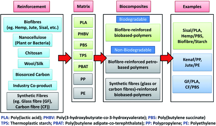
Similar to petro-based polymers, the properties of biobased polymers can be tailored and enhanced by compounding with various fillers or reinforcement to make composites. Biobased composites (biocomposites) can be developed by reinforcing different plastics (both biobased and petro-based) with a variety of inexpensive natural-derived biobased fillers (biofillers) such as flour, plant fibre, biomass, biosourced carbon, etc. However, the sustainable reinforcement for biocomposites is not only limited to plant-based fibres. Agricultural wastes from agro-based industries, consumer food waste, industrial co-product (such as distillers dried grains with solubles (DDGS) and downstream corn oil from bioethanol industry) as well as recycled materials are also defined as sustainable fillers that can be used to develop more sustainable composites with a reduced carbon footprint on the environment.9 Thermoplastic or thermosetting-based polymers can be used with different biobased fibres (biofibre), biofillers or reinforcements to form biocomposites. Biocomposites refers to composite materials that contain one or more naturally derived content, which can be part of the reinforcement phase or matrix phase or both in a composite system. They can be divided into three main groups:10 (a) biofibre-reinforced petro-based polymers (non-degradable), (b) biofibre-reinforced biobased-polymers (biodegradable), and (c) synthetic fibre (glass or carbon fibre)-reinforced biobased-polymers (non-biodegradable) (as shown in Fig. 1). The major development of biocomposites started in the late 1980s.11 The non-degradable nature of many synthetic fibre-reinforced composites have become the main motivation for scientists to develop and discover new biodegradable fibre-based biocomposites to reduce global waste. The use of biofibre in automotive applications includes products such as seat cushions, door panels, dashboards and other interior and exterior body parts.12,13 The innovation and shift of traditional composites to biocomposites for automotive industry has continued to rise due to government regulations. For example, the European Union enforced an automotive directive guideline 2000/53/EG where more than 80% of the total weight of a vehicle had to be reused and recycled in the end-of-life vehicles (ELV).14 The reused and recyclable content was increased to 95% later in 2015.15 This legislation promotes the use of recycled and biodegradable materials to achieve more sustainable automotive developments.
Biofibre can be extracted from plants, like jute, hemp, kenaf, sisal, oil palm, cotton, and bamboo, or from animals, like silk and wool. These can be compounded with various low processing temperature petro-based polymers, such as polyethylene (PE), epoxies, polyester and polypropylene (PP), or with biodegradable polymers, like PLA, PBS, etc. to form biocomposites. These renewable fibres have gained popularity in recent years to aid in developing green biocomposites for use in automotive products. Additionally, they help to reduce the weight and cost of automotive parts as the density and cost of biofibre are comparatively lower than synthetic fibres like glass and carbon fibres (density: flax fibre 1.5 g cm−3 vs. E-glass fibres 2.5 g cm−3; cost: sisal fibre 0.65 USD per kg vs. E-glass fibre 2.00 USD per kg![[thin space (1/6-em)]](https://www.rsc.org/images/entities/char_2009.gif) 13,15,16). Furthermore, the low density of biofibre allows for the possibility of using higher fibre content in composite products, which can reduce the non-renewable petro-based polymer content in products. This weight reduction can help in reducing the fuel consumption of cars and lead to lower carbon emissions.
13,15,16). Furthermore, the low density of biofibre allows for the possibility of using higher fibre content in composite products, which can reduce the non-renewable petro-based polymer content in products. This weight reduction can help in reducing the fuel consumption of cars and lead to lower carbon emissions.
With regards to life cycle assessment (LCA) and energy consumption; it was reported that the LCA of biobased composites (from biobased epoxy resin and natural fibres) was more advantageous than traditional petro-based composite (from epoxy and glass fibres) in terms of energy use and environmental impacts.17 Similarly, Miller18 reported that biofibre/PHBV-based biocomposites exhibited lower environmental impacts than conventional composite materials in terms of greenhouse gas emissions and embodied energy. These are some of the main reasons that make biofibre-based biocomposites an attractive alternative material to replace synthetic fibre-based composites for many automotive manufacturers. Other advantages over synthetic counterparts are acoustic insulation properties,16,19 less energy requirements,20 non-abrasiveness, biodegradability, etc. These biocomposite benefits and increased demand on industry has led to the explosive research and development in this field.
Over the last two decades, many review articles related to biofibre-reinforced biocomposites have been published.13,16,21–26 Different topics on these biocomposites have been thoroughly discussed including: reviews on their tensile properties,27 potential to replace synthetic fibres,28,29 biofibre in PP development,30 kenaf fibre biocomposites,31 flax fibre biocomposites,32 biofibres in conductive polymer composites,33 degradability of biofibre biocomposites,34 coupling agents used,35 compatibility and surface modifications,36–40 biofibre composites selection,41 hybrid biocomposites,42 nano-filler/biofibre hybrid composites,43 flammability,44 automotive applications,45 hybridization with glass fibre,46 and tribological performance.47–51 Although the performance and behaviour of biocomposites have been studied extensively, and many patented products have been fabricated, the use of biocomposites for advanced applications still needs to be explored. This is due to their insufficient mechanical strength and lack of long-term performance studies reported on this new class of sustainable materials. For instance, many works on biofibre/PLA biocomposites have been reported,52–55 however the long-term durability behaviour of these biocomposites are still not understand in depth which restricts them from advanced composite applications.
Biofibres have minimal resistance to environmental degradation. This makes them a good candidate to resolve waste pollution, as they could be degradable under appropriate composting or natural conditions. However, the long-term durability performance of plant-based composites still remains a concern, as material degradation during their service lifetime is undesirable. Both polymer matrix (biobased) and biofibre in the biocomposite can be degraded when constant exposure to harsh environments. The plants cell structures which are susceptible to different environmental attacks are listed in Table 1. Lignin is more prone to UV degradation while hemicellulose is more prone to biological and moisture degradation.56 On the other hand, different polymers exhibited different degradation behaviour and molecular breakdown upon oxidation.
| Lignocellulosics structures | Strength | Thermal degradation | Moisture absorption | Ultraviolet degradation | Biological degradation |
|---|---|---|---|---|---|
| a The number (1, 2, 3 and 4) indicates the effects responsible to the properties. 1 = strongest effect and 4 = least effect. | |||||
| Crystalline cellulose | 1 | 4 | 4 | 3 | |
| Non-crystalline cellulose | 2 | 2 | 3 | 2 | |
| Hemicellulose and lignin compound | 3 | ||||
| Lignin | 4 | 3 | 3 | 1 | 4 |
| Cellulose | 2 | ||||
| Hemicellulose | 1 | 1 | 2 | 1 | |
Durability behaviour and performance of the developed biobased materials are often overlooked when it comes to material characterization and testing. “Material durability” refers to the ability of a given material to withstand a wide variety of physical processes and chemical degradation reactions from the exterior environment. This includes moisture, oxygen and bacteria attacks, mechanical loading, wear and tear, as well as working in extreme temperature conditions. After prolonged exposure to these environments, the performance of polymer composites could be affected due to the breakdown of the macromolecule's structure from the absorption of water and other polar solutions as well as oxidation process. Accelerated aging can be defined as the process required to accelerate the aging mechanism relative to a baseline aging condition. This results in the material reaching the same aged end-state as a real-time aged material but with a shorter time.57 The mechanical properties, dimensional stability, and heat distortion temperature of the composite materials must meet a specific requirement level after performing long-term durability tests in order to assure them to be used in critical automotive parts.58
Aging studies is an important area to research in order to assess a biocomposite's outdoor durability. Taylor et al.59 investigated the long-term aging behaviour of biocomposites from flax fibres and epoxidized soybean oil-based thermosetting resins. The study found that the developed biocomposites exhibited good resistance to accelerated weather conditions. The retention in some of the mechanical properties was superior to the commercial flax/epoxy composites after aging. Mechanical properties like tensile strength, tensile modulus, and hardness could be increased at the early stage of heat aging (annealing effect). Alternatively, the toughness like elongation at break and impact strength is usually reduced after aging. This was due to the decreased chain mobility and increased crosslinking density over time after the test. The enhancement in Young's modulus of coir/PE biocomposites was found to be higher than neat PE after aging.60 Besides the crosslinking effect and chain alignment in the matrix, the stiffness improvement of the biocomposite can be attributed to the short molecules of cellulose fibres which results in an increased crystallinity of the biocomposites. In terms of heat aging behaviour, it was found that the degradation rate of LDPE was increased after blended with palm fibres (0–30 wt%) when subjected to thermo-oxidative aging test.61 The lignin structure in the palm fibre/LDPE biocomposites undergoes an oxidation process, which is evident by the reduction of C![[double bond, length as m-dash]](https://www.rsc.org/images/entities/char_e001.gif) C aromatic absorption peak in the infrared spectra.61 In addition, the increase intensity of vinyl and carbonyl groups can confirm and determine the degree of composite's degradation. More details on different aging studies are discussed in later sections.
C aromatic absorption peak in the infrared spectra.61 In addition, the increase intensity of vinyl and carbonyl groups can confirm and determine the degree of composite's degradation. More details on different aging studies are discussed in later sections.
Most of the studies focused on the performance and characterization of the fabricated biocomposites, with only limited publications and reviews available on the long-term performance of biobased composite materials. The lack of research available on biocomposites durability and the emphasis on the need for this type of research was highlighted in a number of biocomposites articles.32,34 Therefore, the potential of biobased composite materials in advanced applications for use in extreme conditions should be thoroughly reviewed and understood in order to expand their applications further.
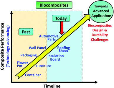
Biocomposites have been applied in many consumer applications such as furniture, wall panel, auto parts, etc. as from past to present (Fig. 2). It is important to understand the mechanism of aging on the newly developed biocomposites in order to improve their durability, performance, and service lifetime when moving towards an advanced applications direction e.g. aircraft parts and structure. In this review, studies on long-term durability behaviour and performance of sustainable biocomposites were reviewed and summarized. The effect of different aging tests such as thermo-oxidative aging, accelerated weathering, natural weathering, water absorption, fatigue, and creep, etc. on the biocomposites behaviour are discussed elaborately. The studies of biofibre modification and other sustainable fillers that are effective in retarding the rate of aging of the biocomposites were also highlighted and discussed. For the first time, the performance of biocomposites and conventional composites were reviewed and compared. This comprehensive review aims to provide useful, new information for students and researchers to advanced further in this area towards designing and development of durable biocomposites for advanced application.
2. Method in measuring the durability performance
All materials are susceptible to aging when exposed to different environments, either in use or while in storage. The change in the material's structure can be either physical (colour or dimensional changes) or chemical (chain scission) after oxidation which is generally known as an aging process. In ambient environments, the rate of oxidative degradation is relatively slow. The oxidation process occurs rapidly at a high temperature. Outdoor environments result in faster aging processes of parts due to the harsh conditions as compared to indoor environments. There are a number of different types of aging processes important to the polymer industry; all of which are critical to evaluate when assessing a polymer's aging performance for its' final product design. The type of aging definition for polymer materials are listed in Table 2. Accelerated aging studies are imitations of specific environmental conditions which can predict the performance and investigate the degradation mechanisms of the test materials. Therefore, aging studies are very important in order to understand the material aging behaviour for the appropriate application.| Type of aging | Definition |
|---|---|
| Natural aging | Aging of polymers through the natural environment |
| Climate aging | Aging of polymers due to climatic conditions of a given earth band |
| Thermo-oxidative aging | Aging of polymers at elevated heat in oxygen rich environment |
| Biological aging | Aging of polymers through the action of living organisms (bacteria or fungus) |
| Mechanical aging | Aging of polymers from constant dynamic and static loads (fatigue) |
| Ozone aging | Aging of polymers by ozone |
| Photo-oxidative aging | Aging of polymers through the effect of visible and ultraviolet light spectrum in oxygen rich environment |
| Chemical aging | Aging of polymers by chemically aggressive solution or substances |
| Artificial aging | Aging of polymers in artificially created conditions |
| Thermal aging | Aging of polymers through heat |
| Light aging | Aging of polymers through the visible and ultraviolet light spectrum |
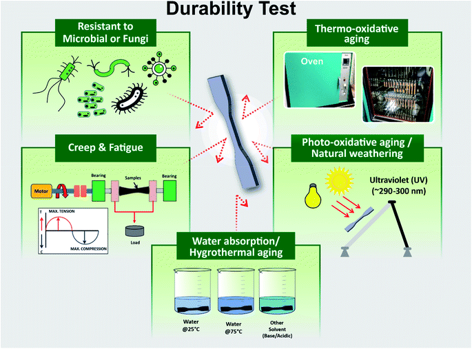
Aging tests are used to evaluate the durability performance of a material. These tests include: conditions in a climate chamber, exposure of natural weathering and UV irradiation, photo-oxidation, thermal-oxidation, water absorption, humidity, microbial, chemical degradation or a combination of these methods. Thermal cycling test (thermal fatigue) studies are also another important durability test conducted with a variation of heating–cooling cycles in a control chamber.63 After being subjected to environment degradation, the samples experience deterioration in terms of molecular weight and mechanical properties, embrittlement and cracks, color fading and spots, deformation and etc. The main symptom of aging and degradation on a polymer can be characterized by the decrease in its molecular weight as a result of bond rupture (chain scissoring).64 Durability is the extent of resistance that the properties of the developed biocomposites have to maintain in these environmental conditions. Fig. 3 presents a diagram of variety of common durability testing techniques. The aging behaviour and mechanism of the virgin polymer are usually less complex than the composite materials. This is due to the presence of different components in the composite such as fillers, fibres, additives, plasticizer, antioxidant etc., where the oxygen from the environment could transfer from one component to another component through the polymer matrix.
2.1 Main characteristic of aged biocomposites
Beside the direct measurement of molecular weight changes by gel permeation chromatography, spectroscopy such as Fourier Transform Infrared spectroscopy (FTIR) and ultraviolet (UV)-visible analysis are the two most popular methods to investigate the degree of degradation of a polymer material after aging, where the possible changes in terms of chemical structures can be identified.65 Chemical compounds like ketones, carboxylic acid, anhydrides and sulfoxides are the common compound form after aging.66 The severity of degradation can generally be quantified by the carbonyl region (peak/area under the curve) or sulfoxide functionalities before and after being subjected to a prolonged period of UV irradiation or thermo-oxidative degradation (sometimes referred to as carbonyl index).66–68 The formation and the evolution of the carbonyl band intensity at ∼1890–1700 cm−1 can usually be observed due to the polymer chain scission reaction where the polymer structural linkages rupture when exposed to elevated temperatures or photo-oxidation.68–70 The products of photodegradation such as alcohols and hydroperoxides could be visible on the band of ∼3400 cm−1. On the other hand, the absorption peaks of lignin, cellulose, and other biobased substances could be degraded significantly after aging.71 The oxidation products of the aged samples and their exact quantification can also be measured analytically by treating the samples with chemical reagents i.e. sulfur tetrafluoride and nitric oxide.72,73 For example, the concentration of carboxylic acids (ketone and ester species) can be determined by sulfur tetrafluoride treatment, whereas concentrations of hydroperoxide, alcohol, and their structures (primary, secondary, and tertiary state) are estimated by nitric oxide treatment.Degradation of polymers usually start from the exposure surface to the inner core. During thermo-oxidative aging, the diffusion of oxygen from the environment into the test sample can be modeled through a classic diffusion kinetic model such as Fick's second law.74 The aging reaction can become more intense with higher temperatures and prolonged duration. Physical changes such as color and alterations in mechanical performance is a more direct and clearly observed effect on material aging. The embrittlement effect after aging due to chains scissoring and chains crosslinking can commonly be seen in the rise of the mechanical modulus from tensile test measurement. Fig. 4 shows the diffusion of the oxidation content and its correlation with the mechanical modulus of a neoprene elastomer sample after it undergoes thermo-oxidative aging. Higher aging test intensity and longer duration increase the distance of oxygen diffusion into the sample from the exposed exterior surface.
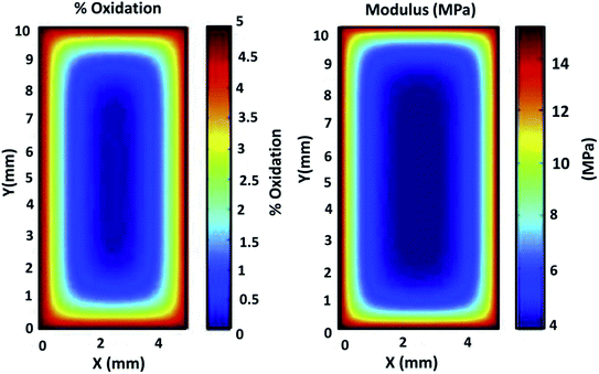 | ||
| Fig. 4 Correlation between oxidation diffusion and the mechanical modulus of neoprene elastomer specimen under highly accelerated thermal aging conditions of 15 days at 125 °C. This figure has been reproduced with permission from ref. 81, Elsevier, Copyright 2013 (License Number: 4707291374971). | ||
Measuring the elongation at break could estimate the loss of the molecular weight and degradation resistance of the aged sample qualitatively.75 Fig. 5 displays the elongation at break of an elastomer as a function of aging time and percentage oxidation content. The elongation at the break of the sample decreases as the aging time and oxidation content increases due to the breakdown of molecular chains. Tensile toughness is very sensitive to molecular chain reduction, structural change of the chains, and morphological properties.76 Furthermore, the matrix surface cracking after thermo-oxidative aging usually results in low impact strength of the aged samples. The degree of deterioration of the interface components of the biocomposites can be investigated through interfacial shear strength and tensile strength. The intensity of the interfacial bonding of the polymer chains after oxidative crosslinking determines the tensile strength after aging.
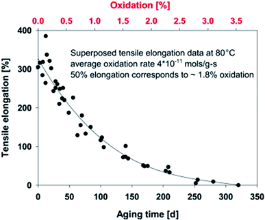 | ||
| Fig. 5 Effect of aging time and oxidation content on the elongation at break of a hydroxy-terminated polybutadiene-based elastomer aged at 80 °C. This figure has been reproduced with permission from ref. 81, Elsevier, Copyright 2013 (License Number: 4707291374971). | ||
The change in morphology of the binary and ternary blends from PCL, PLA, and thermoplastic starch (TPS) after physical aging using atomic force microscopy (AFM) was reported by Mittal et al.77 Significant changes in the blends morphology was observed in the aged samples for 90 days due to the chains relaxation. The polymer domain reduction and interfacial separation of the blends were observed as a function of time.
The physical changes on the appearance and schematic diagram of the intrinsic aging process before and after undergoing thermo-oxidative aging test is shown in Fig. 6. The color of the samples changed significantly after they were aged for 1000 hours in a high temperature aging oven under constant airflow. From a number of works reported on aged polyamide (PA) 6, the chromophore structure could be α-keto carboxyl,78 conjugated enones,79 pyrrole groups80 and amino compounds of NH2CH2CH2CH2CH2COCOOH and NH2CH2CH2CH2CH2COCOOCH3 that are causes for discolors and the yellowish of the aged samples.
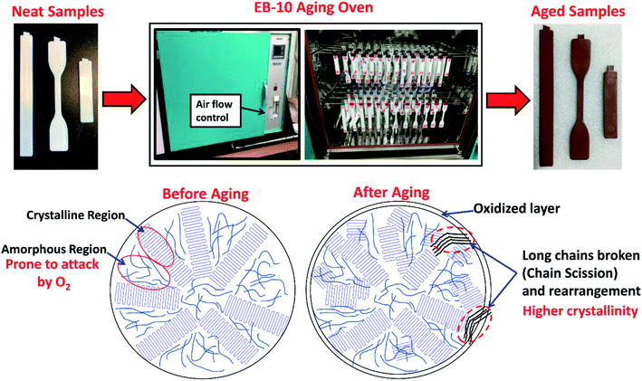 | ||
| Fig. 6 Physical and intrinsic structure changes of a semicrystalline polymer in high temperature aging oven. | ||
2.2 Aging on thermal properties
The alteration in molecular chains arrangement, filler–matrix interfacial adhesion, and interaction during aging caused changed in the overall biocomposite's thermal properties. This included the change of degree of crystallinity, activation energy, and enthalpic relaxation.82 The aging behaviour of amorphous and crystalline structures in polymer composites demonstrated a different thermal behaviour profile when subjected to aging. The effect of aging on the crystallinity of the samples can be increased or decreased depending on the aging intensity. A very similar concept to the annealing process, the degree of crystallinity rises when a polymer undergoes different thermal-oxidative aging processes, except during aging experiments held at longer durations in a higher temperature oven, which leads to the deterioration of the polymer chains. There are two factors that could cause an increase in the degree of crystallinity of the polymers. The first can be due to the relief of thermal stress (caused during the fabrication process) of the samples83 where the spherulites could grow larger in size. The aging process in a high temperature oven or chamber allows the molecular chains to be rearranged and re-organized. Another process can be due to the re-aligning of broken chains (due to chain scissoring) into a more orderly structure in amorphous regions of the semicrystalline portion (as shown in Fig. 6 above). Due to the weaker bonds and cleaved free areas found in the amorphous region of the polymer chains, the aging process occurs more readily throughout the non-spherulite zones.84 The degree of crystallinity of neat PLA was found to increase up to ∼50% after undergoing accelerated weathering.85Physical aging even at room temperature for a long duration could affect the glass transition temperature (Tg)86 and other thermal properties of a polymer.87 The change in Tg of an aged polymer can be detected by dynamic mechanical analysis (DMA). The crystallinity of PLA could be increased when it is heated above 37 °C for a prolonged period. The Tg of the aged biocomposites could shift to a higher temperature due to the crosslinking process and chain mobility restriction in the early stage of aging. On the other hand, a decrease in Tg could be observed in the aged sample when chain scission was dominant. The long-term indoor stability of biocomposites from pine wood flour and PHBV were investigated by Chan et al.88 It was reported that the incorporation of a nucleating agent i.e. talc and boron nitride increased the rate of crystallization of the PHBV-based biocomposites. The biocomposites interfaces were weakened after aging for one year in ambient conditions due to shrinkage, moisture uptake, wood swelling which leads to secondary crystallization and stress localization of talc in the biocomposites. The detailed aging process is presented in Fig. 7a. The stiffness enhancement with the presence of talc in the wood/PHBV biocomposites was offset after one year of indoor aging (Fig. 7b).
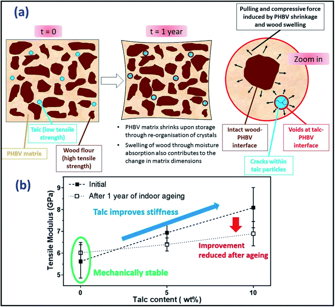 | ||
| Fig. 7 (a) Schematic diagram of aging mechanism of wood/flour PHBV biocomposite with the presence of talc and (b) its tensile modulus variation after one year of indoor aging. This figure has been reproduced with permission from ref. 88, Elsevier, Copyright 2018 (License Number: 4785480371285). | ||
Due to molecular chain scission (macromolecule breakdown), formations of additional unstable and impure components like carbonyls and hydroperoxides in the biocomposites after aging, shifting of the melting temperature (Tm) to a lower temperature of the biocomposites was noted.89 Abu-Sharkh and Hamid90 reported an interesting result on the thermal behaviour on the date palm fibre/PP biocomposites after natural weathering aging. They observed the Tm of both neat PP and compatibilized PP-based biocomposites were significantly reduced over 9 months of natural weathering. However, the Tm of uncompatibilized date palm fibre/PP biocomposite was stable throughout the aging test (Fig. 8a). This can be attributed to the less stability of the maleated PP. In the case of artificial weathering, the Tm of neat PP was less stable than both uncompatibilized and compatibilized date palm fibre/PP biocomposite (Fig. 8b). In addition, broadening of the Tm could be visible due to the degradation of crystallite structures of the polymer after severe aging.91
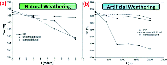 | ||
| Fig. 8 Melting temperatures, Tm, measured by DSC of PP-based biocomposites after undergoes (a) natural weathering and (b) artificially weathering as a function of weathering time. This figure has been reproduced with permission from ref. 90, Elsevier, Copyright 2004 (License Number: 4758351272633). | ||
Lévêque et al.92 developed a multiscale approach to analyze and model the thermal aging behaviour of carbon fibre/epoxy composite structures. The developed models were based on the volume and surface effects; results demonstrated that the computational data closely resembles the experimental thermal aging data. However, there are still many environmental variations and other intrinsic factors unaccounted for that are affecting the final properties of the composites during an aging test. The Arrhenius equation (eqn (1)) can be used to roughly estimate the temperature–time relation of an accelerating thermal aging duration and condition of a materials.93
 | (1) |
2.3 Effect of different processing method
There is a tendency that air and other volatile substances may be trapped inside the biocomposite during processing and curing40 which may affect the properties in long-term use. Due to the presence of micro-voids, biocomposites are more vulnerable to moisture diffusion and high variation in mechanical properties as compared to neat polymers. Different process engineering and parameters could yield different intrinsic structural and homogeneity of components within a biocomposite. The mechanical properties of composites can be substantially different even if the same raw materials and formulation were used, but with different processing techniques. This phenomenon has also been reported in durability studies. The green biocomposites of PLA reinforced with apple fibres and sugar beet pulp processed with extrusion followed by injection molding has been found to affect their aging behaviours.82 Clemons and Ibach96 compared the moisture absorption behaviour of wood/HDPE biocomposites processed with different processing techniques. They found that the biocomposites produced from extrusion absorbed the most moisture, followed by compression moulded sample, and the injection molded samples showed the least moisture absorption after two weeks of the water soaking test. They correlated this to the lower void content and better packing density of the biocomposites produced from the injection molding process. This was further supported by the work from Stark et al.,97 where different manufacturing methods could give different surface characteristics, which can affect their durability performance. Wood-based biocomposites were prepared with three different processing techniques i.e. injection molded, extruded and planed. Injection-molded samples showed more polymer rich surfaces than the extruded and planed samples, while planed samples displayed the highest wood phase presence and exposure on the surface. The higher packing density from the high pressure injection molded samples exhibited better interfacial adhesion and hence more stable when exposed to weathering test.97Sustainable bioplastics and biocomposites have gained considerable interest in recent years due to their environmental friendliness as compared to conventional polymer composites. However, their performance under different extreme environment conditions is still an open question. In order to investigate and enhance their durability performance, considerable work on various types of biocomposites have been conducted and will be reviewed in the subsequent section. Depending on the application of the materials, the accelerated aging test may not accurately predict the value or represent the actual aging condition of the materials (e.g. in aerospace composite materials).81,98 This can be due to the variation of weather between seasons as well as different geographical regions between countries.59
3. Photo-oxidative and weathering
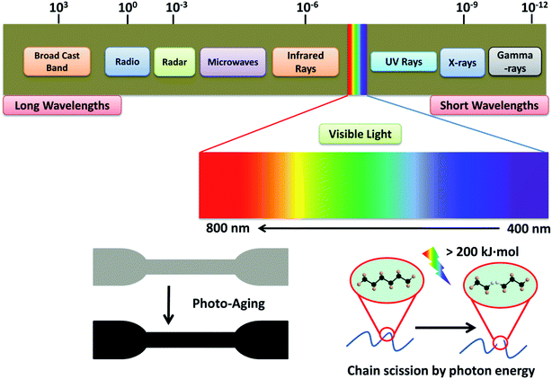
Light can induce the degradation of polymers. Photo-oxidative degradation is a decomposition process where the material's chemical structure is broken down after prolong light exposure. UV stabilizers are typically added in polymers that are sensitive to UV light. Upon UV exposure, the wavelength energy of irradiation waves is the main factor causing the molecular chain breakage in the composite materials (Fig. 9). Typical polymer chains can be excited and detached at the energy around 290–420 kJ mol−1 and the energy of the UV radiation is in the range of 290–410 kJ mol−1.99 This UV energy is enough to initiate the degradation (free radical produce) and is expected to accelerate in the presence of an oxygen rich environment. The quantum energy from the wavelength of UV radiation can cause microcracks on the surface of degraded polymers.100,101 The energy of the irradiation wavelength at 295 nm is enough to break the C–N, C–C, C–O, Si–O, N–H and O–O polymer bonds.102 For PLA, UV energy of 400 nm or less could break the covalent bonds of C–O and C–C,103 and produce polymer radicals from chain scission. These polymer radicals may link to the main chain of a neighboring molecule to give a branched molecule.100 The aged samples usually experience considerable color fading and excessive embrittlement as a result of crosslinking, which leads to microcracking on the surface. At the same time, the mechanical properties are also drastically affected after prolonged UV exposure.Different polymers exhibited different photo oxidative degradation. Fig. 10 shows the degradation pathway for common packaging polymers i.e. PE, PP and PS.104 The degradation involves three stages: initiation, propagation, and termination. UV light initiated the breakdown of the polymer chains, while free radicals are formed when the C–H bonds were broken by the light action.105 The process continues through reaction with oxygen in the environment to form peroxy radical and hydroperoxides.106 Termination stage take place when inert products are formed through the combination of two radicals. However, these inert products (ketones, aldehydes, etc.) are more susceptible to UV-initiated degradation, as they contain unsaturated double bonds.104 Therefore, the molecular weight of the polymers reduces as the degradation continues through these breakdown reactions.
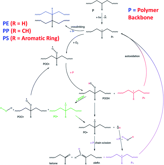 | ||
| Fig. 10 Degradation pathway upon UV-initiated degradation for common packaging polymers (PE, PP and PS) starting on their backbone structure. This figure has been reproduced with permission from ref. 104, RSC, Copyright 2015. | ||
Dintcheva and La Mantia107 investigated the durability of commercial starch-based biodegradable polymers for potential use in agriculture film applications. They found that both maize starch polymers and synthetic biodegradable polyesters degraded drastically after undergoing the photo-oxidation process. A significant reduction in elongation at break shows poor resistance of the polymers to the UV irradiation. However, the durability performance of the biodegradable polymers can be improved after incorporation of small amounts of commercial UV stabilizers. In addition, they reported that the benzophenone compound seems to work slightly better than the benzotriazoles, the triazine, and the sterically hindered amine among the UV stabilizers investigated.
Aging can also be associated to the decline of the mechanical performance of materials. Depending on the aging intensity, the mechanical properties of the polymer composites decrease over time except for the modulus. The mechanical property's retention after photo-aging can be calculated with a simple formula as in eqn (2), where the SV stands for strength value (before and after aging) which can be impact strength, flexural strength, and tensile strength. For the biocomposite to be use in real applications, its percentage retention rate should not be less than 50% after weathering exposure.
 | (2) |
Conducting a full experimental setup for biocomposites under natural weathering exposure conditions require a lot of time and man power. Accelerated weathering tests are usually preferable over natural weathering aging, as they can be carried out with either a QUV (UV lamp) or Q-Sun (Xenon lamp) accelerated weathering chamber. Fig. 11(A–C) shows a typical QUV/spray accelerated weathering tester and its schematic diagram respectively.
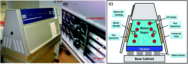 | ||
| Fig. 11 (A and B) The QUV/spray accelerated weathering tester. Figures adapted with permission from ref. 108, the Royal Microscopical Society, Copyright 2016 (License Number: 4761390867194) and (C) its schematic drawing diagram. | ||
Buffum et al.94 investigated the mechanical properties of seven different service-ware made from biodegradable waste fibre and plastics i.e. bagasse, a bagasse bamboo blend, PLA, wheat straw, fibre pulp, potato starch, and a bamboo bulrush wheat straw blend after they were subjected to UV exposure and humidity. They found that most of the mechanical strength of the biopolymers decreased significantly, with PLA experiencing at least 50% reduction in tensile strength and tensile modulus. The UV exposure at the 315 nm band could accelerate the hydrolysis degradation of the ester linkage in the PLA.109 The effect of humidity was not as severe as that of UV radiation. A higher rate of degradation was reported when PLA films were subjected to elevated temperatures and relative humidity simultaneously.109 The reduction in mechanical properties can be attributed to the hydrolysis of ester linkages of PLA, which decreased with the increase of temperature and relative humidity.94,109 The study concluded that although the investigated bioplastics service-ware products possessed similar properties to polystyrene (PS) in the as-received condition, the biodegradable bioplastics were more sensitive to UV exposure and humidity as compared to traditional plastics, like PS. The mechanical strength of the PLA product can be expected to decrease significantly after 6 months under ambient conditions.94
Fibrous biocomposites such as bagasse and fibre pulp-reinforced biopolymers exhibited significant resistance to the loss of properties over time as compared to its pristine form.94 Gorrasi et al.110 studied the effect of photodegradation on thermal, mechanical, and electrical behaviour of their tailor-made hybrid clay-carbon nanotube-reinforced PLA bionanocomposites. They observed a drastic decrease in Young's modulus of neat PLA after UV exposure over time due to the chain scission of the macromolecular structures. The Young's modulus of PLA shows less reduction with introduction of clay-carbon nanotube nano-fillers in the PLA films. The formation of anhydride groups (carbonyl products) was the main photodegradation mechanism of PLA upon UV exposure.69,70 Composite materials filled with various inorganic fillers produce different chemical radicals or products during photo-oxidative aging. A higher rate of oxidation was observed when PLA was filled with different minerals like montmorillonite (Cloisite), Sepiolite, and Fumed silica.70 The metal ions and metal impurities present in mineral fillers accelerated the photo-oxidation of the polymer through the hydroperoxide decomposition process.
In another UV-aging resistant study of biocomposites reported by Gardette et al.,69 the PLA was reinforced with calcium sulphate anhydrate CaSO4 β-anhydrite II (dehydrated gypsum from a by-product of lactic acid) to produce biocomposites; the influence of filler content and particle size on aging behaviour was also investigated. The PLA biocomposites showed formation of similar photoproducts as observed in the neat PLA. The rate of degradation of PLA was found to increase with the increasing filler loading, as well as with the smaller CaSO4 filler particles size in PLA.
Pucciariello et al.111 found that the blends of LDPE and PS with addition of straw lignin displayed less UV degradation. They proposed that the presence of phenolic groups in lignin could act as an antioxidant and radical scavenger which results in delaying the UV-degradation process.111 However, the hydrophilic nature of lignocellulosic biofibre in biocomposites could promote hydrolytic degradation; which would then produce a loss in mechanical performance.112
Similar to PLA, PBAT is also prone to UV-aging. Zhu et al.113 prepared biocomposite films of PBAT-reinforced with nanosilica-supported ultraviolet absorber. Their results showed that the PBAT biocomposite film prepared through chemical grafting technique exhibited superior UV aging resistance as compared to the biocomposite prepared by physical mixing.
The internal structure of biofibre can also be significantly affected with prolonged exposure to UV. The lignin and hemicelluloses structures were changing as a result of macromolecular scissoring.114,115 The formation of different chemical compounds from the biofibres could act as chromophores (degradation radiation initiators) which could accelerate the degradation rate of the polymer matrix.89 Mixture products such as ketones, acids, lactones, and esters were found after aging at different carbonyl peaks such as 1712, 1750, and 1775 cm−1.116 The absorption bands of carbonyl, vinyl or anhydride increased with increasing UV exposure time, which reflects the progression of photo-oxidation (Fig. 12). It was observed that the photodegradation of palm fibre/PP was less than pineapple leaf fibre/PP biocomposites (due to a lower absorption band in carbonyl region).116 These results demonstrate that the use of different biofibres could affect the photo-aging performance of the biocomposites. The difference in the degradation rate and mechanism could be due to the lignin content and organic composition of the different biofibres. Due to the rationale that degradation happens for both fibres and matrix, increasing the fibre content should affect the photo-oxidation rate as well. Fig. 13 shows the increase in the area under the IR absorbance peak at carbonyl, vinyl, and anhydride regions as a function of UV aging time for linear low-density polyethylene (LLDPE) and PLA-based biocomposites doped with nutshell powder extract (NSE). The authors found that areas under both carbonyl and vinyl IR peaks of UV aged LLDPE were reduced after incorporation of NSE up to 3% (Fig. 13a and b).117 On the other hand, the areas of anhydride and vinyl IR peaks of UV aged PLA were unstable and increased when doped with NSE (Fig. 13c and d). This demonstrates that NSE is more effective in retarding the photo-oxidation degradation process in LLDPE as compared to PLA.
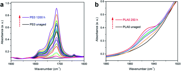 | ||
| Fig. 12 Changes in the IR spectra (carbonyl region). (a) Neat LDPE film and (b) neat PLA film after UV aging. This figure has been adapted with permission from ref. 117, ACS, Copyright 2017. ACS Sustain. Chem. Eng., 2017, 5(6) 4607–4618. | ||
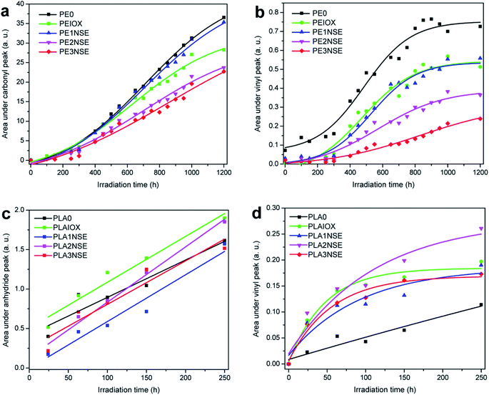 | ||
| Fig. 13 Effect of various NSE contents on the area changes on IR peak absorbance in (a) PE carbonyl groups, (b) PE vinyl groups, (c) PLA anhydride groups and (d) PLA vinyl groups after exposure to UV for 250 h. This figure has been adapted with permission from ref. 117, ACS, Copyright 2017. ACS Sustain. Chem. Eng., 2017, 5(6), 4607–4618. | ||
The UV degradation of biofibre-based biocomposites can be reduced by hybridization with other synthetic fibres. Abdullah et al.118 reported that the hybridization of kenaf fibre with PET fibre-reinforced polyoxymethylene (POM) hybrid composite had better retention in mechanical properties than that of the neat kenaf fibre/POM composites. The tensile strength of the composite dropped by 50% while that of the hybrid composite with hybridization of fillers dropped by only 2% after being subjected to moisture, water spray, and UV exposure in an accelerated weathering chamber for 672 hours. Its suggested hybrid biocomposites of kenaf/PET fibres may be more suitable for outdoor applications or for automotive parts as compared to only kenaf fibre-based biocomposites.
A material's performance after subjected to outdoor natural weathering is another important aspect to evaluate the durability of the developed biocomposites for outdoor application. Natural weathering tests are very similar to UV tests where the oxidative photodegradation response of the materials can be studied and assessed by manipulating several factors such as the intensities of the exposure length, humidity, and moisture etc. However, natural weathering is more susceptible to the variation of environmental factors such as sunlight, rain, moisture, wind, fungal, and microbes attack as compared to tailor made accelerated weather equipment or UV aging oven. Enhancement of the long-term weathering performance of the biocomposites remains a challenge. With proper conditioning, it was reported that both artificial climate chambers and natural weathering yields considerable aging effects to the wood-based biocomposites.119 Table 3 presents the comparison and equivalent aging duration of accelerated UV-aging test in Weather-Ometer for different climate conditions of natural weathering. These conditions could simulate approximately one year of natural weathering exposure in 2–3 months with 300–400 nm wavelength of UV light radiation.
| Location | Climate type | Average solar radiant exposure in one year | Equivalent duration for the Weather-Ometer exposurec | ||
|---|---|---|---|---|---|
| Totala | UVb | In days | In months | ||
| a Solar radiation measured between 300 nm and 3000 nm.b Solar radiation measured between 300 nm and 400 nm.c Regarding UV radiations only, according to 168 cycles of 120 min (EN ISO 4892-2). | |||||
| Florida, USA | Sub-tropical | 6588 MJ m−2 | 280 MJ m−2 | 95 | 3.2 |
| Bandol, France | Mediterranean | 5500 MJ m−2 | 382 MJ m−2 | 69 | 2.3 |
| Arizona, USA | Desert | 8004 MJ m−2 | 334 MJ m−2 | 79 | 2.6 |
Consequently, aging behaviour can vary considerably when tested in an accelerated simulated weather chamber and natural weathering exposure in different climate countries' environment. The sunlight intensity and rain fall varies geographically. Even though the weathering test can be studied in an accelerated weathering chamber with appropriate UV light and moisture condition setup, the simulated weathering chamber cannot directly simulate the real environmental condition. Part of this is because the solar radiation cannot be mimicked completely with the use of an artificial UV lamp.121 Recent studies and set-up conditions of weathering tests of biocomposites are presented in Table 4. Although there are many accelerated weathering studies reported according to the standard procedure, only a handful of studies have related their research to the actual aging progression and effective service life of the biocomposites. Full setup of experiments still need to be done in the real working conditions. However, the general behaviour on the durability performance comparison between composites can be determined.
| Composites | Weathering condition & standard | Irradiation intensity & wavelength | Chamber environment | Test duration | Results | Ref. |
|---|---|---|---|---|---|---|
| a Abbreviation: WPCBPs: waste-printed circuit boards; WF: wood flour; SiCO: capsicum oleoresin encapsulated porous silica; PF: palm fibre; PALF: pineapple leaf fibres; MAPP: maleated polypropylene; Mt: montmorillonite; HNT: halloysite nanotubes; EVA: ethylene vinyl acetate copolymer; NS: not stated; PBS: poly(butylene succinate); FDE: farm dairy effluent; SD: wood sander dust. | ||||||
| WPCBP/WF/PP | UV-340A accelerated weatherometer, ISO 4892-1 | 0.83 | 50 °C | 15 days | WPCBP and WF enhance the retention rate of mechanical prop. of PP after UV exposure | 122 |
| Higher amount of WPCBP increases the carbonyl index due to the presence of transition metals in WPCBP which accelerate the photo-aging | ||||||
| Linseed cake/PLA | UV light, ISO 4892-3 | 0.76 W m−2, 340 nm | 60 °C | 250 and 500 h | Incorporation of biofiller accelerates the degradation | 123 |
| Hydrolytic degradation on amorphous phase (initial UV aging – 250 h) | ||||||
| Hydrolytic degradation on crystalline phase (later UV aging – 500 h) | ||||||
| SiCO/PLA | Xenon lamp, ASTM G155-13 cycle 1 | 0.35 W m−2 (340 nm) | 63 °C, 30% humidity, light and water spray for 18 min | 260 and 520 h | Tensile properties, thermal stability and rheology decreased after aging, while, % crystallinity increased | 124 |
| PF/PP, PALF/PP | Mercury pressure lamps | 400 watts (300 nm) | 60 °C | 30, 40, 50 h | PF/PP shows better properties retention than PALF/PP after photo-aging due to higher lignin content of PF | 116 |
| Wood fibre/PP (bleached and unbleached) with MAPP | Fluorescent bulb UVA, ASTM G154-00a | 0.68 W m−2 (340 nm) | 50 °C, 2 h condensation per cycle | 150, 400, 600, 800 and 1000 h | Both bleached and unbleached wood fibre composites shows reduction in mechanical prop. After accelerated weathering | 56 |
| Reduction in mechanical prop. was due to degradation of lignin, chain scission of PP and deterioration of fibre–matrix interface | ||||||
| Wood flour/PP with MAPP | Weather-Ohmeter (xenon arc | 3500 W lamp, 60 W m−2, 300–400 nm | 60 °C | 14 days | Recycled of the UV-aged WF/PP were able to recover the initial properties of the WF/PP biocomposites | 120 |
| WF/PP, lignin/PP, cellulose/PP | QUV accelerated weathering, ASTM G154 | 0.89 W m−2, at 340 nm | 60 °C, 4 h condensation per cycle | 960 h | Composite containing lignin was more sensitive to photodegradation (from color change results) | 125 |
| Lignin/PP showed better retention in flexural strength and modulus, better hydrophobicity and less cracks, on UV-aged surface than PP biocomposites | ||||||
| Starch/WF/PLA with 15% of glycerol | Fluorescent lamps, ASTM G154-06 | 0.89 W m−2, at 340 nm | 4 h condensation per cycle | 300, 600 and 1200 h | Carboxylic acid was formed on the surface after UV-aging | 126 |
| Glycerol exhibited stabilize effect on the UV durability of the biocomposites | ||||||
| Lignin/PLA | Mercury lamp | 39 mW cm−2, 200–700 nm | 30 °C, 60% humidity | 600 h | Free surface energy increased after weathering | 115 |
| Lignin/PLA show less reduction in tensile and impact strength than other samples after UV-aging | ||||||
| Mt/PLA (1 mass%) | Fluorescent lamps, SAE J2020, ASTM G154-05 and ISO 4892-3 | 0.49 W m−2, 310 nm | 70 °C, 4 h dark condensation per cycle | 50, 100, 150 and 200 h | PLA nanocomposite with 1 mass% Mt clay showed extremely beneficial effect on the durability performance after accelerated weathering (good mechanical prop. retention) | 127 |
| HNT/PLA | Fluorescent lamps, cycle-C of the ISO 4892-3 | 0.49 W m−2, 310 nm | 70 °C, 4 h dark condensation per cycle | 300 h | Intensities of the distinctive IR bands of PLA were decreased after weathering degradation due to photolysis, hydrolysis and chain scission | 128 |
| Reinforcing effect of HNT in PLA could compensate the loss in mechanical prop. After aging | ||||||
| TiO2/EVA/PLA | Accelerated weathering, ISO 4892/3 | NS | 60 °C, 8 h irradiation, 4 h humidity condensation per cycle | 8–56 cycles | Different TiO2 crystal form could affect the degree of photodegradation | 129 |
| Rutile TiO2 do not enhance the degradation, but anatase and mixed crystals TiO2 nanoparticles promoted the degradation of the nanocomposites | ||||||
| WF/PP with pigments | Accelerated weathering, ASTM G 154 | 0.89 W m−2, at 340 nm | 60 °C, 8 h irradiation, 4 h condensation per cycle | 240, 480, 720 and 960 h | Incorporation of pigments was proven to be more effective staining method for improving color stability during weathering as compared to the use of dye WF | 130 |
| WF/HDPE | Accelerated weathering, ASTM G154-12a | 0.89 W m−2, at 340 nm | 60 °C, 8 h irradiation, 4 h condensation per cycle | 500, 1000, 1500, and 2000 h | Weathering degradation of the biocomposites is affected by the type of WF | 131 |
| A. Mangium/HDPE shows better surface color and properties stability after aging than E. urophylla and P. caribaea/HDPE | ||||||
| ZnO/WF/HDPE | UVB lamps, ASTM D4329 | 313 nm | 60 °C, 8 h irradiation, 4 h condensation per cycle | 500, 1000 and 1500 h | Surface cracks, contact angle changes and mechanical prop. loss were reduced with increasing ZnO content | 132 |
| Incorporation of ZnO changed the photodegradation mechanism of the biocomposites | ||||||
| Teakwood sawdust/PBS | ASTM-G154 cycle A | NS | 60 °C, 8 h irradiation, 4 h condensation per cycle | 5 cycles, 60 h | Tensile modulus increased while flexural properties decreased | 112 |
| Loss in mechanical prop. was due to the hydrolytic degradation which induced by the hydrophilicity of lignocellulosic biofibre | ||||||
| Biofibres (Oak, cotton burr and guayule bagasse)/HDPE | Accelerated weathering, Fluorescent UV lamps, ASTM G 154 | 0.85 W m−2, 340 nm | 45 °C, UV irradiated for 4 h (60 °C), condensation for 4 h (50 °C) | 2200 h | Coupling agents helped to retain the mechanical prop. Of biocomposites after UV exposure | 133 |
| Biofibres accelerates the UV degradation rate of HDPE | ||||||
| Flax fibre/epoxidized sucrose soyate | 40 watt UVA-340 fluorescent lamps | 0.5 W m−2 | 40 °C, 4 h UV and water condensation | 1000 h each side | The properties of biocomposites reduced after weathering | 134 |
| Fibre treatments aid in improving resistance to property degradation after weathering | ||||||
| FDE/PLA, SD/PLA | UVA-340 fluorescent lamps | 60 °C, 8 h UVA radiation, 4 h condensation | 0, 250, 500, 750 and 1000 h | Larger extend of mechanical prop. deterioration was observed for FDE/PLA as compared to SD/PLA biocomposites after UV-aging | 135 | |
Free radicals formation process on the chain structures of the polymer composites as a result of photodegradation can further propagates as the weathering test continue. Moreover, the chain scission along with deterioration of the fibre–matrix interfacial bonding after degradation causes a severe reduction in mechanical performance. As a result, the molecular weight, Tg, surface properties, mechanical strength, flexibility and intermolecular forces of the biocomposite deteriorated after aging. Yew et al.136 conducted a weathering experiment for 8 weeks at 70% relative humidity on the PLA biocomposites consisting of rice starch (RS) and epoxidized natural rubber (ENR). Severe degradation was observed for the PLA biocomposites, where the tensile properties were deteriorated after weathering. The property retention of the RS/PLA biocomposites was higher when compared to the PLA-reinforced mixture of RS with glycerol and RS-glycerol water mixture. The addition of ENR increased the degradability rate of the biocomposites due to the oxidation process of unsaturated sites of ENR. The effect of natural weathering after 130 days on the Cloisite 30B nanoclay/PLA bionanocomposites was investigated by Zaidi et al.137 It was reported that the incorporation of nanoclay in PLA not only accelerated the natural weathering degradation, but also caused a reduction in thermal stability of the biocomposites. This can be due to the complex reactions and absorption of nanoclay additives, which includes catalytic effects of impurities as well as the degradation of the ammonium cations of montmorillonite (MMT). The authors also concluded that the presence of nanoclay did not alter the photo-oxidative degradation mechanism of PLA, it only accelerated degradation rates. The formation of photo products i.e. vinyl unsaturation, anhydrides, carbonyls, and hydroperoxide groups were observed due to the complex chain scission reactions during degradation.137
The mechanical properties of the jute fibre-reinforced phenolic biocomposites decreased significantly after exposure to natural weathering for two years.138 The deterioration could be more intense if the moisture content of the tested environment was high, while the colour fading of the samples continued with increased exposure time. The stress induced on the biocomposites interface from variation in the thermal expansion and shrinkage upon exposure resulted in resin cracking and fibre pop-out. The authors also observed the growth of black spots, which were confirmed as hyphae fungus due to the high moisture content of the outdoor environment.138 Significant changes in surface roughness, physical (colour), thermal, and mechanical properties of the biocomposites after the accelerated weathering test in Weatherometer was reported by Mehta et al.125 A surface coating is recommended for the biofibre-based biocomposites if it is designed for outdoor applications where it may subjected to a huge variation in moisture and heat. Polyurethane coating138 and chemical surface modification125,139 have been proved to be effective methods in slowing down the weathering degradation of the biocomposites.
Spiridon et al.114 observed changes in severity of biocomposites after accelerated weathering degradation on PLA by addition of modified fibres. They found that the enzymatically modified fibres (organosolv lignofibres) resulted in better preservation of the surface chemical, mechanical, and thermal properties as compared to unmodified fibres after weathering. Abu-Sharkh and Hamid90 investigated the aging of date palm leave fibres in PP biocomposites under natural and artificial weathering conditions with UV stabilizers. They found that the biocomposites with the help of UV stabilizers (i.e. Irgastab and Tinuvin-783) were more aging resistant than neat PP. In addition, the use of maleic anhydride (MA)-grafted PP in the composite system could reduce the overall aging resistance of the composite due to the lower stability of maleated PP.90 Islam et al.140 found alkali treated long hemp fibre/PLA biocomposites are more resistance to accelerated aging by UV irradiation and water spray than untreated biocomposites.
The durability performance of PLA/hemp fibre biocomposites after accelerated weathering, water spray, and condensation cycles have been investigated by Sawpan et al.85 It was found that the overall mechanical properties were decreased when increasing the test cycles. However, the impact strength of the PLA/long hemp fibre biocomposites were found to increase after accelerated weathering due to the plasticising effect as a result of porous structure formation after fibres debonding and leaching.140 The PLA was found to deform severely after accelerated weathering aging.85 The reinforcement of hemp fibres aided in retaining the stability of PLA due to presence of stiffer cellulose fibre in the matrix (Fig. 14a). In addition, the weight of the PLA and its biocomposites were found to decrease up to ∼0.30% after 64 cycles of accelerated weather aging85 (Fig. 14b). This can be attributed to the degradation of materials (blistering and erosion) when exposed to a severe weathering environment. The weight reduction on PLA biocomposites after aging due to materials degradation was also reported elsewhere.141,142 On the contradiction, some works reported an increase in material weight after aging due to absorption of the moisture by biofibres when exposed in wet environment.140 The weathering effect on the degree of degradation of biofibres can be reduced by the incorporation of synthetic fibres to form a hybrid biocomposite. Mohammed et al.143 reported superior thermal stability of kenaf fibre/GF polyester as compared to only kenaf fibre/polyester biocomposites when exposed to natural weathering for 3 months. The Tg of the composites were found to decrease with an increasing weathering period due to the molecular weight reduction in the polyester. The improvement in thermal stability of the hybrid biofibre/GF composites were attributed to the presence of the inert inorganic silica content, which can resist thermal expansion or contraction. The deterioration degree is less in hybrid biofibre/synthetic-based biocomposites as compared to the biofibre-based biocomposites.144
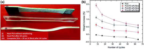 | ||
| Fig. 14 Effect of accelerated weathering aging cycles (UV light, water spray and condensation according to ASTM G154) on PLA and its biocomposites on (a) dimension changes and (b) weight changes. This figure has been reproduced with permission from ref. 85, SpringerLink, Copyright 2019 (License Number: 4710330395191). | ||
4. Bionanocomposites for durable applications
Due to the high surface energy and very high aspect ratio in the nano-range size (1–100 nm) for nanomaterials, the incorporation of nano-fillers or fibres into polymers can significantly increase their performance in many aspects such as dimensional stability, rheological, mechanical, electrical, thermal, and barrier properties. The thermal stability of the biopolymers have been shown to improve by using different nano-fillers such as clay145,146 and carbon nanotubes. Dispersion of nano-fillers in biocomposites are one of the popular research areas used to improve the overall composite performance. However, the incorporation of nanoclay in polymers have shown negative effects in terms of durability when compared to neat polymer, especially in the UV-light degradation process.72,76,147–154 Clay, such as MMT was ineffective in retarding the degradation of polymer. The acceleration of degradation of the organoclay-polymer composites can be due to the reaction of the degradation of alkylamonium151 and the reactions between the antioxidant and the MMT's ions forming iron or other metal species (catalytic effect).76,150 The introduction of clay in starch has shown significant improvement in thermal stability and water absorption resistance.155,156 It was confirmed that the clay/PLA nanocomposites demonstrated superior thermal stability under oxidative environments as compared to clay/PLA microcomposites.145,157 This was due to the higher degree of phase separation microstructure in the case of microcomposites. On the contrary, the addition of clay in PLA showed a decreasing trend in its thermal stability.158 The addition of both micro- and nano-MMT in polymers could accelerate the rate of photo-oxidative degradation in comparison to neat polymers.154 This can be attributed to the influence of MMT and the reactions of its ammonium ion.Good resistance to high temperature hydrolytic degradation was reported after incorporating appropriate amounts (1%) of graphene oxide (GO) in PA11 through a polymerization method.159 The highly asymmetric planar of GO nano-sheets could inhibit the water molecule diffusion into the nanocomposites (Fig. 15a). However, there was no significant reduction in the rate of hydrolytic degradation when further increase the GO content to 5% (due to agglomeration) (Fig. 15b).
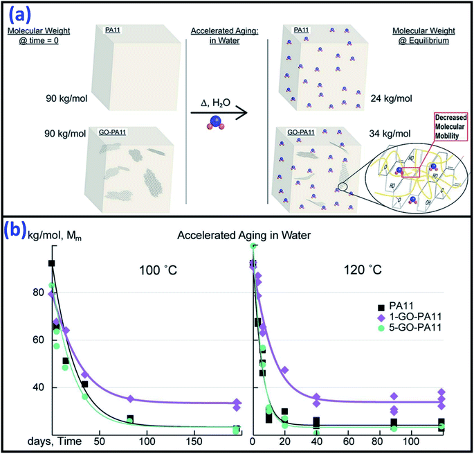 | ||
| Fig. 15 (a) The hydrolytic degradation resistance mechanism of GO nano-sheets in PA11 and (b) molecular weight reduction of the PA11 and its GO/PA11 nanocomposites after accelerated aging in water at 100 °C and 120 °C. This figure has been reproduced with permission from ref. 159, Elsevier, Copyright 2017 (License Number: 4758410550345). | ||
Another fast emerging field of bionanocomposites is based on the use of nanocellulose. Nanocellulose can be extracted from plants (i.e. nanofibrillated and cellulose nanocrystal) and bacteria mediums (i.e. bacteria nanocellulose). The use of a small amount of nanocellulose in polymers can boost the performance of biocomposites significantly, provided that sufficient dispersion was achieved during processing. A number of works have been conducted by several authors on the reinforcing effects of nanocellulose in polymer biocomposites, such as a summary and thorough review discussed and reported by Lee et al.160 Similarily, studies on durability performance and aging behaviour of these biocomposites are limited. Cellulose nanowhiskers/PLA bionanocomposites films have shown to improve thermal stability and reduce the rate of hydrolytic degradation of PLA.161 The improvement was mainly due to the higher crystallinity of the nanocellulose which limits the water diffusion through the creation of tortuous path. On the other hand, the reverse effect was reported in the cotton-based nanowhiskers/PLA bionanocomposites.162
The use of other nano-fillers i.e. zinc oxide (ZnO) and titanium dioxide (TiO2) were also found to have a positive effect on enhancing the durability performance of biocomposites.132,163 The addition of ZnO in PP/wood biocomposites decreases the mechanical strength loss and surface degradation after weathering.132 The authors attributed this to its capability to absorb UV radiation. The addition of different additives and flame retardants (i.e. aluminium trihydrate, melamine, zinc borate, TiO2 and graphite) into PP-wood biocomposites was investigated by Turku and Kärki.164 They observed that TiO2 can prevent surface discoloration due to its UV-light absorption ability. However, TiO2 can facilitate chemioxidation of the biocomposite.164 Small amounts of silver (Ag) nanoparticles were able to improve the UV stability of HDPE.165 The HDPE degraded significantly when exposed to UV irradiation after 500 hours as shown in the drastic increase in the carbonyl index, vinyl index and hydroxyl/hydroxyperoxide index (Fig. 16). These indexes were reduced significantly when increasing the content of Ag nanoparticles. Metallic nanoparticles are effective inhibitors to the photo-oxidation process of the polymers.
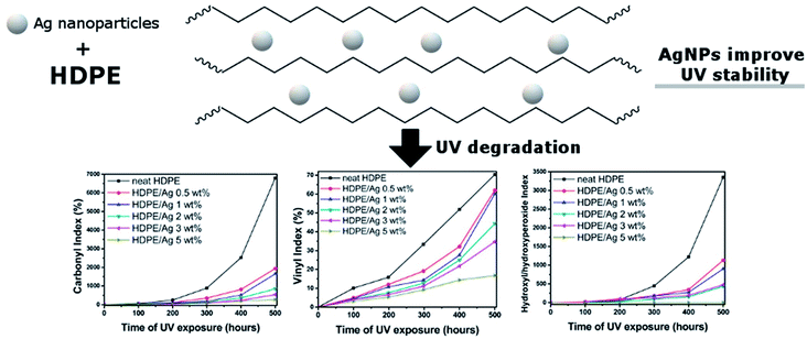 | ||
| Fig. 16 UV stability of HDPE improved with silver nanoparticles as indicated in the reduction in the carbonyl index, vinyl index and hydroxyl/hydroxyperoxide index of HDPE after UV aging. This figure has been reproduced with permission from ref. 165, Elsevier, Copyright 2018 (License Number: 4758991253218). | ||
5. Thermal stability and thermo-oxidative aging
One of the disadvantages of biofibre-based biocomposites is their narrow processing window when compared to conventional composites. Lignin, a main component in biofibre starts to degrade at temperatures around 190–200 °C.27,166 The mechanical properties of the fabricated articles decline as fibre degradation occurs when processed at high temperatures due to the degradation of lignocellulosic materials, which results in losing their intrinsic structures. Therefore, the matrix choice for the biofibre-based biocomposites is usually limited to commodity plastics and thermosets. Engineering plastics like nylon, PET, and PBT matrix are relatively rare in biocomposite fabrication due to the degradation of biomaterials. The decomposition temperature and thermal stability of biofibre-based biocomposites can be improved with proper processing, and modification to improve the biofibre–polymer interaction. The thermal stability of biofibre/polystyrene (PS) biocomposites were found to be higher after surface modification and treatment as compared to a neat PS and untreated biofibre system due to the better fibre–matrix adhesion.167,168 In regards to the degradation of biofibre with high temperature processing polymers, some considerations of works have been reported. With proper processing temperature, melt controlling on the heating zone of the extruders, and the use of a second feeder close to the extruder die, it is possible to process engineering plastics with natural fibre.169 The attempt to reduce the processing temperature of engineering plastics by incorporating halide salt with biofibre is another important approach to develop biofibre/engineering plastic biocomposites.170 The addition of lithium chloride (LiCl) halide salt has showed promising effects in reducing the melting temperature of PA171 due to the formation of ionic interactions between the salt and PA molecules.172 Other coupling agents and plasticizers have also been reported as effective additives to modify the engineering plastic melting temperatures; thus making it feasible to produce biofibre/PA-based biocomposites.173,174Biofibre-based biocomposites displayed a clear advantage when thermal and noise insulation types of application are required (critical in automotive parts). This is due to the tubular and hollow structure of the biofibre which provide effective insulation against heat and noise.175 Some works have been found that lignin can act as stabilizer and antioxidant to prevent the aging of polymer due to its antioxidant activity.111,176,177 The thermal stability of lignin/PHB biocomposites were observed to increase with the increasing content of the lignin amount.177
The thermal performance and thermal aging behaviour of biocomposites made from natural flour and PLA have been reported by Kim et al.178 They found that incorporation of flour decreases the degradation temperature of PLA. However, destarched cassava flour showed higher thermal stability than pineapple flour-based biocomposites due to its higher lignin content. The degradation temperature can be further increased with the help of compatibilizers due to the enhancement of the crystallinity; this results in higher mechanical performance of the biocomposites.178 On the thermal aging test, the tensile strength of flour-PLA biocomposites with and without compatibilizer were deteriorated due to the presence of gaps between components and shorter PLA molecules as compared to neat PLA.178
A thermo-oxidative aging experiment is an accelerated aging test conducted to investigate the aging performance of a composite material in the air rich environment at an elevated temperature. The heat accelerates the oxidation process where the oxygen slowly diffuses into the samples over time and slowly degrades the polymer chains. Basically, the degradation intensity and oxygen diffusion into the test samples can be divided into three regions as presented in Fig. 17. Region I is the outer most surface region with direct contact to the environment and is usually an oxidized polymer. The diffusion intensity is reduced in Region II resulting in a mix of oxidized and unoxidized polymer. The last phase refers to Region III which is located in the inner part of the samples where most of the polymer remain unoxidized. These degradation regions can also refer to two-phases regions or unreacted-core models.179,180 This build-up of an oxidized layer can be detected by infrared microscopy as seen in Fig. 18a. Wei et al.181 studied the fracture behaviour of PA after thermo-oxidative aging at 180 °C for 48 hours. Three stages of aging (Stage I: early stage, Stage II: moderate stage and Stage III: severe stage) were observed; tensile properties such as elongation at break were greatly affected (Fig. 18b and c). The crack initiation and propagation of PA during elongation strain is influenced by the thickness of the oxidized layer. At Stage II and Stage III region, the elongation at break reduced significantly due to the larger diffusion and extension of oxygen into the sample.
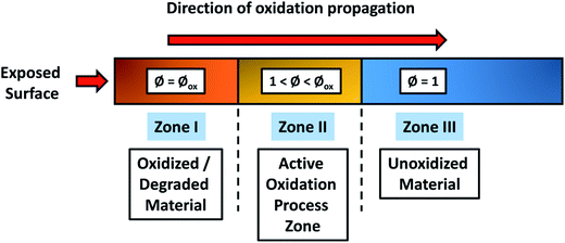 | ||
| Fig. 17 Schematic of the three-zones during thermo-oxidative degradation. The active zone separating the oxidized and unoxidized regions. This figure has been redrawn and reproduced with permission from ref. 182, Elsevier, Copyright 2008 (License Number: 4707300513800). | ||
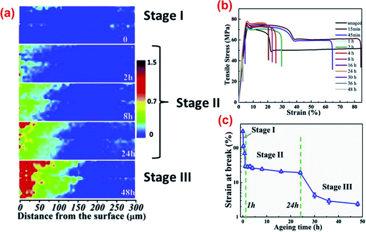 | ||
| Fig. 18 (a) Infrared images of carbonyl index in the cross-sectional region from the expose surface, (b) stress–strain curves of PA6 and (c) elongation at break value after 48 hours of thermo-oxidative aging at 180 °C. This figure has been reproduced with permission from ref. 181, Elsevier, Copyright 2018 (License Number: 4758370882321). | ||
The build-up of an oxidized layer during thermo-oxidative aging could act as a barrier to prevent further oxidation propagating towards the inner core of the composite.183 At the same time, volatilization process of low-molecular weight molecules takes place. As the aging severity and duration increase, the oxidized layer thickness reduces due to the reactive zone saturation (Fig. 19). However, the inner core of the composite is still well protected throughout the aging process.
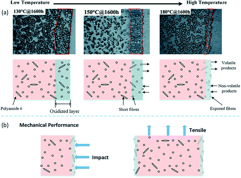 | ||
| Fig. 19 Schematic diagram representation of oxidized layer buildup during thermo-oxidative aging of short fibre/PA6 composites from low temperature to high temperature. This figure has been adapted with permission from ref. 183, RSC, Copyright 2017. | ||
The accelerated thermo-oxidation test is usually carried out at different oven temperatures and durations depending on the tested polymers and the test standards followed. However, test conditions must be appropriately selected where changes in properties (physical, chemical and mechanical) of the tested samples occur without severely distorting the samples. Acceleration factor can be used to estimate the acceleration test conditions to the actual service life. For example, the thermo-oxidative aging test of high impact polystyrene at 80 °C for 1400 hours corresponds to about ten years of service duration.184 For every increase of 10 °C in the aging test, the aging rate of the samples roughly doubles. Table 5 summarizes the test condition of thermo-oxidative aging studies conducted by different researchers on different thermoplastic composites. Note that there are not many research studies conducted on the long-term thermo-oxidative aging for biocomposites. Therefore, the research and strategy to improve the durability of biocomposites is of the utmost importance as this class of materials are gaining in popularity over the conventional composites – most likely due to global sustainability and pollution awareness.
| Composites | Oven temperature (°C) | Test durations | Heat stabilizers/antioxidant/additives used | Results | Ref. |
|---|---|---|---|---|---|
| a Abbreviation: LGF: long glass fibre; GF: carbon fibre; BioC: biocarbon; TOA: thermo-oxidative aging; SBR: styrene butadiene rubber; ENR-50: epoxidised natural rubber with 50 mol% epoxidation; MnS: manganese stearate; PBT: PA10T: poly(decamethylene terephthalamide); iPP: isotactic polypropylene; PVC: poly(vinyl chloride); NBR: nitrile butadiene rubber; HMS-PP: high melt strength polypropylene; HIPS: high impact polystyrene; FR: flame retardant; deca-BDE: deca-bromodiphenylether; TPO: thermoplastic polyolefins; SGF: short glass fibre; PPS: polyphenylene sulfide. | |||||
| LGF/PA6 | 160 | 10, 20, 30, 40 and 50 days | Copper salt, phosphorus acid | The presence of stabilizers showed better retention in terms of dynamic and static mechanical properties | 78 |
| GF/PA6, talc/PA6, BioC/PA6 | 140 | 1000 h (ISO 188:2011 standard) | — | GF/PA6 composite retained better mechanical prop. than talc/PA6 and BioC/PA6 composites | 187 |
| GF/PA6, CF/PA6 | 90, 130, 150 and 180 | 200, 400, 800 and 1600 h | — | CF showed better stabilizing effect than GF in long-term TOA test | 183 |
| Sago starch/LDPE | 70 | 1, 2, 3 and 4 weeks | SBR, ENR-50, MnS as pro-oxidant | Pro-oxidant i.e. unsaturated elastomer and metal salts enhanced the degradation rate of the biocomposites | 188 |
| GF/PBT, talc/PBT, BioC/PBT | 155 | 1000 h (ASTM D3045-92 standard) | — | GF/PBT showed the most stable in retaining its mechanical properties after TOA as compared to talc/PBT and BC/PBT | 185 |
| LGF/PA10T | 160 and 200 | 10, 20, 30, 40 and 50 days | — | Decline in mechanical performance due to interface debonding of the composite | 189 |
| iPP, HMS-PP | 90 | 6, 12 and 20 days (ASTM D 3045-2003 standard) | Irradiation with gamma rays | Irradiated samples indicates less TOA degradation as compared to neat iPP | 190 |
| PVC/NBR thermoplastic elastomers | 100 | 3, 7, 14 and 21 days (BS 7646 standard) | — | Crosslink density increases with aging time | 191 |
| Mechanical prop. Increase and decrease after reaching maximum as the aging test continue | |||||
| HIPS, HIPS-FR | 80 | 1400 h | Fire retardant, deca-bromodiphenylether (deca-BDE) | HIP containing deca-BDE improved aging prop. | 184 |
| Flame retardant behaviour of HIPS-FR is retained even after aging | |||||
| TPO-based biocomposites | 110 | 250, 500, 750 and 1000 h (ISO 188-2011 standard) | Irganox, Songxtend anti UV additive (Tinuvin P) | The incorporation of phenolic antioxidants provide good resistance to TOA degradation | 192 |
| SGF/PPS | 140, 160, 180 and 200 | 5300 h | — | Degradation rate increases with increasing the TOA temp. | 193 |
| Fatigue life decreases after aging due to oxidation | |||||
| Metal salt/PA6,6 | 110 | 7000 h | Metal salts | Zn, Cu and mixture of CuCl2/KI showed effective long-term stabilizer which could prevent oxidative propagation reactions during TOA | 91 |
Radicals generation during oxidation process alter the intrinsic structure of the polymer composites. The physical and chemical degradation after thermo-oxidative aging resulted in significant changes in the composite appearance and color.185 The color of neat PBT changed from white to brown after heat aging in an aging oven for 1000 hours as presented in Fig. 20. Significant changes in color was also observed for GF/PBT and talc/PBT composites after aging except for biocarbon/PBT biocomposites due to black in color. Oxidation rate of the composites can be reduced through the use of antioxidant and stabilizers. Metal salts antioxidant (Mn+) are commonly used to prevent the free radicals' propagation in polymer chains. Unstable compound formation after oxidation like carbonyl groups and hydroperoxides could be decomposed further into nonradical products, hence, the formation of OH˙ radicals could be prevented.78,186 The decomposition reactions mechanism is presented in eqn (3) and (4) below:
| ROOH + Mn+ → RO˙ + M(n+1)+ + OH− | (3) |
| ROOH + M(n+1)+ → ROO˙ + Mn+ + H+ | (4) |
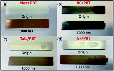 | ||
| Fig. 20 The changed of color for the PBT-based composites before and after undergoes thermo-oxidative aging at 140C for 1000 h. (a) Neat PBT, (b) biosorced carbon-reinforced PBT, (c) talc-reinforced PBT and (d) glass fibre-reinforced PBT. This figure has been adapted with permission from ref. 185, Wiley, Copyright 2018 (License Number: 4707300726359). | ||
Beside physical properties, the mechanical properties of the samples changed significantly due to the alteration of their intrinsic chemical structures. Joseph et al.139 observed increased tensile properties except for elongation of the banana-fibre/phenol formaldehyde biocomposites after undergoing thermo-oxidative aging in an air oven at 100 °C for 3 days. They attributed the finding to the induction of crosslinking chains and the embrittlement effect of the samples. The tensile modulus of the biofibre-based biocomposites could be increased after thermal aging. This can be due to the further interfacial adhesion at high temperatures and development of a transcrystaline region in the composites.194 With an increase of crystallinity after thermo-oxidative aging, the mechanical properties such as elastic modulus and hardness of the PLLA-based biocomposites were increased.195 Substantial deterioration in mechanical properties may take place as the aging test continues for longer periods in the oven due to further weakening of the bonds. The density of biocomposites were found to increase after undergoing thermo-oxidative aging in an air rich oven due to the shrinkage of their volumes and the growth of oxidized layers on their surfaces.185 In other work reported by Kim et al.178 the shrinkage ratio of neat PLA was found to increase more than 5% in the length direction after being subjected to a thermal aging cycle. Negligible shrinkage was detected in the PLA-flour biocomposites under the same testing conditions. The authors attributed this to molecular chain restrictions in PLA after reinforcement, which resulted in less shrinkage as compared to neat PLA.178
Effective surface treatment on biofibre could improve the long-term durability aging of the PLA-based biocomposites. Kyutoku et al.196 conducted a surface coating on cellulose fibre with different compatibilizers and incorporated them with PLA. They found that the long-term durability performance of PLA biocomposites was enhanced with surface treated cellulose fibre. The lower molecular weight epoxy coating was more effective in inhibiting the heat aging degradation of the biocomposites due to excellent interfacial adhesion between phases.
DMA is a useful tool that can be used to detect the degree of degradation after thermo-oxidative aging. The shift in Tg of polymer composites to a higher temperature confirms the chains restriction due to the crosslinking reaction during the aging process.78,185 The crosslinking of polymer chains along with the embrittlement effect of the composites contributes to the enhancement in mechanical modulus and heat deflection temperature.
The modelling of oxygen diffusion on the polymer samples have been discussed by a number of research groups.197–199 Yu and Pochiraju182 modelled the long-term degradation due to oxygen and moisture uptake in polymer-matrix-composites (PMC) based on a three-dimensional finite element method (FEM) micromechanical analysis. The oxygen diffusion, as in the thermo-oxidative degradation and moisture uptake in PMC based on the homogenization method with diffusivity tensor components, were used to directly estimate the fibre and interphase diffusivities. The fibre and matrix phase degradation as well as the fibre–matrix interphase region that could affect the diffusion behaviour are required for a long-term degradation prediction model. The diffusion limited oxidation kinetic model could predict the rate of oxidation degradation and the lifetime of the samples in that particular environment.81 However, most of the developed models could only accurately describe the behaviour in a moderate aging temperature condition. The behaviour of the oxygen transportation into the polymer under high temperature are subjected to many ambiguities.
6. Biofiller and additives towards durable biocomposites
With an increasing demand for bioplastics and biocomposites, the continuous search and development of sustainable additives and biofillers have become an enticing research area in recent years. Biofillers are advantageous for biodegradable plastics compared to traditional fillers, because both components are biodegradable at their end of life in the appropriate environment. For example, the incorporation of distillers dried grains with solubles (DDGS) into polyhydroxyalkanoate (PHA) increases the biodegradation rate significantly over 25 weeks in soil.200 However, the durability of the biocomposites remain a concern. In addition, biofibres are sensitive to the high temperature processing conditions that can reduce their properties due to burning and degradation. Browning, odor, and deterioration of mechanical properties of the biocomposites occur when biofibre process with polymer at 200 °C (thermal degradation of biofibre). In order to fulfill certain drawbacks of biofibre such as limited processing temperature and low thermal stability of biofibre, several new sustainable biobased materials have been used and reported by scientists and researchers as alternatives to biofibre for high processing temperature engineering plastic matrices.Besides traditional natural fibre, biosourced carbon (biocarbon) is a relatively new class of biofiller which is growing interest in the biocomposites field.9,201–203 Biocarbon can be derived from various plant biomasses through a pyrolysis process in an inert atmosphere with conditions at or above 400 °C. Sources other than plant biomass such as chicken feather can be used to produce biocarbon as well.204 In the past decades, biocarbon, also known as biochar, was typically used as a soil fertilizer for soil amendment purposes in early application. Other emerging applications of biocarbon include electric double layer capacitor,205 supercapacitors,206 enzyme immobilization,207 asphalt flow modifier,208 etc. The use and investigation of this carbonaceous biofiller in composite applications have increased in recent years. Some of the studied biocarbon feedstocks are generated from bamboo,209 wood,210 perennial grasses,202,211 and poultry feathers.212 Different biomass sources can result in significant variation of the biocomposite properties.201,202 The incorporation of biocarbon in polymers have been found to improve the stiffness and flame retardance of polypropylene (PP),213 electrical conductivity of polyvinyl alcohol (PVA),214 mechanical properties of PLA,209 and heat deflection temperature (HDT) of PA.215 The incorporation of bamboo charcoal in PP biocomposites increases the crystallinity and mechanical performance.216 The incorporation of the biocarbon in polycarbonate/recycled carbon fibre hybrid biocomposites demonstrated an increase in reinforcing efficiency, which resulted in higher tensile and impact performance.217 In addition, a reduction in weight as compared to other traditional mineral-based composites is another distinct advantage of biocarbon-based biocomposites.218
Some studies have been devoted to the long-term durability behaviour of biocarbon/polymer biocomposites. The moisture uptake of biocarbon/nylon biocomposites was lower as compared to neat nylon.219 The authors also found the durability performance of the biocarbon/nylon biocomposites were comparable to talc/nylon conventional composites. Due to the thermal stability of biocarbon, the biocarbon-based biocomposites also showed superior thermal stability and fire resistance.220,221 The tensile properties of biocarbon-based thermoplastic polyolefins can be sufficiently maintained with the help of phenolic antioxidants after 1000 hours of thermo-oxidative aging.192 Another important factor which affects the final structures and properties of biocarbon is the pyrolysis time and temperature. Behazin et al.202 investigated the properties of two types of Miscanthus-based biocarbon, pyrolyzed at ∼500 °C and ∼900 °C respectively as reinforcement in PP. They found a higher modulus and better impact toughness for high temperature pyrolyzed biocarbon as compared to low temperature pyrolyzed biocarbon. They attributed these results to differences in the polarities of the biocarbon when pyrolyzed at different temperatures. The different affinity of the synthesized biocarbon can be used with different polymer matrices. For example, non-polar polymer i.e. PP exhibited better compatibility with a higher pyrolyzed temperature biocarbon (due to absence of functional groups), while polar polymer like nylon exhibited better compatibility with lower pyrolyzed temperature biocarbon (due to preserve of functional groups) (as presented in Fig. 21). Therefore, biocarbon exhibited high potential as a new polymer filler for making biocomposite222 since it is derived from sustainable biobased feedstock.
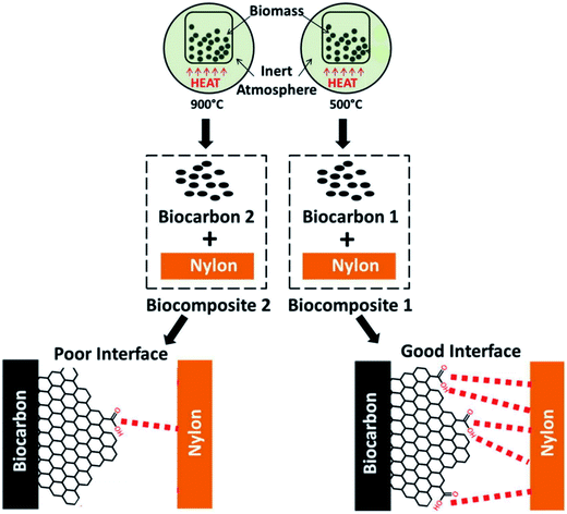 | ||
| Fig. 21 Schematic diagram of biomass pyrolyzed at different temperatures (500 °C and 900 °C) and their affinity with nylon. This figure has been reproduced with permission from ref. 223, Elsevier, Copyright 2017 (License Number: 4758391432795). | ||
Chitosan is another important biobased, nontoxic, biodegradable, and biocompatible bio-filler which is derived from chitin (cationic linear polysaccharide). Chitin is one of the most abundant resources next to cellulose, which occurs naturally in the structures of the shells of all marine creatures and of the exoskeletons of every insect. Due to its biocompatibility, chitosan-based biocomposites have been used in various medical applications such as bone tissue regeneration, drug delivery, antibacterial applications, and wound healing. Chitin can be processed into various forms such as fibre, powder, film, etc. for biocomposite applications. During biocomposite fabrication, chitosan can be used as a matrix component or a reinforcement component depending on the extraction and processing technique. Water absorption studies of up to 60 days with polyester bioplastics after incorporation with chitosan and hydroxyapatite have been reported by Correlo et al.224 They found that the water absorption and diffusion coefficient of blends were increased with increasing content of chitosan. The addition of hydroxyapatite in blends showed lower water uptake and achieved equilibrium water uptake faster. Spiridon et al.225 developed a green composite from PLA, chitosan, and keratin fibres. They reported that the degradation of PLA was faster in the presence of chitosan after being subjected to accelerated weathering. The incorporation of keratin fibre helped in retaining the properties of biocomposites in terms of mechanical and thermal performance. The complex viscosity of the biocomposites were reduced after weathering test due to the chain scission.
Although most of the durability testing on chitosan-based biocomposites was inferior, its durability applications in terms of antimicrobial properties were promising. In the antibacterial study conducted by Atay and Çelik226 on the effect of chitosan in polymer composites, they concluded that chitosan was very effective in antibacterial properties for inhibiting the growth of Staphylococcus aureus (S. aureus). The colloid-type chitosan additive was more effective than powder-type of chitosan additive. The antibacterial activities of the cellulose–chitosan composite films were also found to increase when increasing the content of chitosan against Escherichia coli (E. coli) and S. aureus.227 The widely discussed antibacterial activity might be due to the positive charge (protonated ammonium group) presence in the chitosan, which reacted with the negative charges of the bacterial cell membranes. In comparison to other biobased structures like starch, cellulose, and galactomannans, chitosan appears to be more flexible in terms of chemical structure modification in its C-2 position.228 This allows for better tailoring ability for it to be used in many desired applications by attaching to specific functional groups within the structures.
In other biobased additives studies, Lee and Wang229 developed a non-toxic biobased-coupling agent from lysine-based diisocyanate and used it together with bamboo fibres, PLA, and PBS to fabricate biodegradable biocomposites. The degradation temperature, tensile properties, interfacial adhesion, and water resistance of the biocomposites were found to improve with the biobased-coupling agent. Moustafa et al.230 using waste seashells as a biofiller for acrylonitrile–butadiene–styrene copolymer (ABS) found that the thermal stability and flame retardancy were improved.
Biocomposites have a high market value and are a possible substitution to conventional composites for a better and sustainable future. Intensive research on durability studies and property improvement of the sustainable biofillers reinforced polymer composites are critically needed in order to accelerate the substitution process. Natural crop fibres, agricultural and food wastes have been extensively studied and explored as reinforcement for polymers. However, few studies have reported different biofillers other than natural fibre. The discovery of effective biofillers for better thermal stability and durability of biocomposites still requires further innovation.
7. Water adsorption and hygrothermal aging
Biofibres usually suffer from moisture and humidity issues due to the presence of cellulose-rich structures and hydroxyl groups on the fibre surfaces. Similar to oxygen diffusion during thermo-oxidative aging, the diffusion of water molecules into polymers after water absorption caused changes in both the chemical and physical characteristics of the polymer, which affected the mechanical performance. Most biocomposites absorb moisture in humid environments or when immersed in water, however the rate of degradation and water uptake behaviour is different for each material. Moisture absorption in biofibre-reinforced composites can cause huge variation on physical, mechanical, and thermal properties,231 which is different in value when observed in an ambient environment. Plasticization effect is the most significant mechanism observed and reported after polymers are immersed into water due to the interactions between the water molecule and polymer. Significant reductions in Tg may be observed when moisture content is increased in the biocomposite due to swelling, which increases the composite's volume.232 The extent of Tg variation is generally proportional to water sorption in the polymer. This is due to the water molecule breaking the hydrogen bonds and van der Waals forces in the polymers, which results in an increase of chain segment mobility.233 However, the changes in Tg does not solely depend on the amount of water diffusion. The behaviour displayed was completely different when the water sorption test involved a variation in temperature above ambient temperature (hygrothermal aging).233In general, water absorbed into the biofibre-based biocomposites after immersion in water can be categorized into two types i.e. bound water and free water (Fig. 22). Bound water are water molecules that are dispersed in the polymer matrix and are attached to the polar groups of the polymer, while free water are water molecules that are transported into the polymer through micro-cracks and voids.34,234 The water absorption of biofibre is mainly due to the cellulose cell wall surface, which is rich in hydroxyl groups. The mechanism of moisture diffusion in polymer composites have been discussed in several studies.235–237 There are three mechanisms possible during the moisture absorption process:
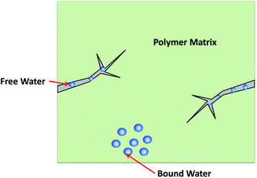 | ||
| Fig. 22 Water transport into the polymer matrix in different ways. This figure has been reproduced with permission from ref. 34, Elsevier, Copyright 2013 (License Number: 4707300862584). | ||
(1) The water molecules diffuse into the micro gaps between polymer chains.
(2) The water molecules migrate into the voids and gaps at the fibre–matrix interfaces.
(3) The water molecules diffuse into the fibre through microcracks in the matrix and cause swelling of the fibres.
The fibre swells after certain period of immersion in the water, which leads to micro-cracking of the matrix and results in high water diffusion into the composites. The capillary action starts after the water molecules flow through the fibre–matrix interface and leads to high diffusivity.238 Hence, the water uptake and water absorption rate generally increases when there is an increase in fibre volume fraction. According to the typical Fickian's moisture absorption model, most of the water absorption behaviour of composite samples behave linearly in the beginning of the test and reach saturation later in the test. The water absorption is expected to be higher in high volume fraction loading of biofibre as compared to low volume fraction loaded biocomposites.
The water absorption percentage of the biocomposites can be calculated with the general equation below:
 | (5) |
Hydrolytic degradation studies on biocomposites appear to be more common than studies on other types of degradation as mentioned previously. In terms of mechanical properties, studies have shown that the tensile and flexural properties of biofibre-based biocomposites decrease significantly after aging in water as compared to a control polymer,239–242 while the impact toughness increased.243 The extent of the mechanical strength and modulus loss depends on the aging time and temperature.244 The reduction in mechanical properties is due to water molecules penetrating into the hydrophilic surface of the biofibre which decreases the fibre–matrix interaction and disturbs the overall integrity of the composite system as shown in Fig. 23. The water uptake of the composites was found to increase with fibre content due to the increased cellulose content.241,242 On the other hand, some authors observed positive effects on the mechanical properties of the biofibre/polymer biocomposites after absorption test.237,245 The authors attribute this to the swelling of the fibres which eliminate the gaps between the fibres and the matrix; thus increasing the shear strength of the composites.
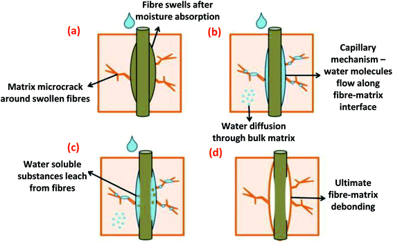 | ||
| Fig. 23 Biofibre-based biocomposite interface deterioration mechanisms. This figure has been adapted with permission from ref. 34, Elsevier, Copyright 2013 (License Number: 4707300862584). | ||
Muñoz and García-Manrique246 studied the water absorption behaviour and its effect on the mechanical properties of flax fibre-reinforced bio-epoxy green biocomposites using a resin transfer molding (RTM) method. Higher elongation at break and tensile strength was observed for water immersed flax-epoxy biocomposites as compared to dry biocomposites for both 40% and 55% of fibre volume fraction samples. This can be due to the swelling of the fibres in the matrix after water absorption. The swelling effect of fibre closes the fibre–matrix interface gaps which is caused by shrinkage and incomplete wetting of the fibre-resin interface during composite processing. This eventually led to an improvement in the fibre–matrix interaction and increased the mechanical properties of the composites. Similar results was also reported by Karmaker et al.245 where the gaps between jute/PP due to the thermal shrinkage of the matrix has been filled by the swelled fibre after 14 days of water immersion conditioning. The results were confirmed by a shear strength test where an increase in shear strength was observed after water immersion. The study also reported that the rate of water absorption depended on the fibre orientation. However, the absolute water content after maximum absorption time remained the same. The tensile stress of the hemp biocomposites was found to increase after water immersion for 888 hours.237 However, a reduction of tensile strength was observed for 3 and 4 layered hemp-based biocomposites. The diffused water molecules act as plasticizing agent in the composite system, which results in an increase in the flexibility and elongation at break of the samples.237,247 Chen et al.248 reported that the interfacial shear strength of the bamboo-based biocomposites decreased significantly in the first nine days of the water absorption test. They found that there was no further deduction in the interfacial shear strength of the biocomposites when the test continued up to 100 days. The water absorption of jute, sisal, ramie and kenaf fibres have been compared and reported.249 The authors found that ramie fibres exhibited the lowest water absorption as compared to jute, sisal and kenaf fibres.
Réquilé et al.250 reported a moisture absorption swelling mechanism of biocomposites in his recent study (Fig. 24). During the manufacturing process, the influence of biocomposite geometry, structure, biofibre distribution, and content might generate excessive compression stress within the biocomposite Fig. 24A and B). This phenomenon results in orthotropic hygroscopic expansion after exposure to a high moisture environment with a higher out-of-plane longitudinal strain as compared to transverse strain direction (Fig. 24C).
 | ||
| Fig. 24 Schematic drawing of orthotropic hygroscopic expansion of biocomposites at the (A) initial state, (B) after manufacturing and curing, and (C) after increasing the relative humidity. This figure has been reproduced with permission from ref. 250, Elsevier, Copyright 2019 (License Number: 4758380711911). | ||
It has been noted by many researchers that the water absorption of biofibre-reinforced polymer biocomposites can be reduced by chemical modification and treatment of the biofibre surface. The water absorption behaviour of biocomposites were greatly dependent on the chemical treatment. This is because chemical pre-treatment on the biofibre surface can effectively change its hydrophilic behaviour to a hydrophobic behaviour and lead to a better interfacial adhesion between phases. Hence, a reduction in water uptake can be achieved. Fig. 25 shows the schematic representation of the jute biofibre/PLA biocomposites before and after surface treatment with alkali (NaOH) and a combination of NaOH and silane. The combination of NaOH and silane treatment increased the phase adhesion between jute biofibre and PLA as compared to only NaOH treatment, which ultimately lead to a higher overall performance of the developed biocomposites.251 The enhanced fibre–matrix interaction can reduce the sensitivity to water absorption and results in improved resistance to moisture uptake and hydrolytic degradation. As a result, the mechanical properties and other performance attributes were enhanced.
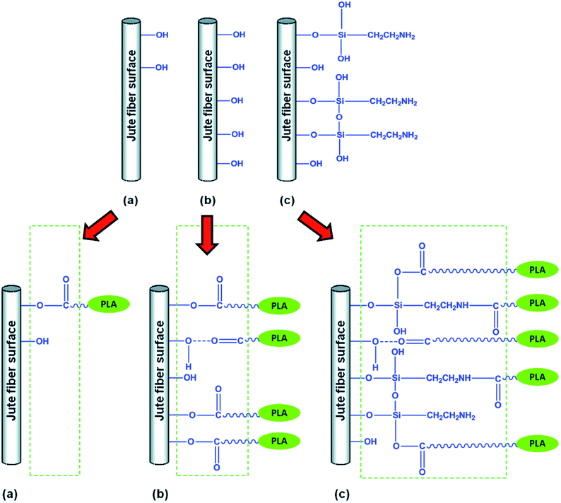 | ||
| Fig. 25 Schematic representation of the compatibilization of jute biofibre and PLA biocomposites after chemical treatment; (a) untreated jute biofibre/PLA, (b) NaOH jute biofibre/PLA and (c) NaOH + silane jute biofibre/PLA. This figure has been reproduced with permission from ref. 251, RSC, Copyright 2016. | ||
Pickering et al.23 reviewed in detail the use of chemical modifications in different biofibres recently. Some of the effective treatments included benzylated reactions,252 mercerization (alkali treated e.g. NaOH),253–255 maleic anhydride grafted polypropylene (MAPP),244 acetylation,256 silane,249 isocyanate treatment,257 peroxide treatment,258 acrylic acid,40 permanganate,249 zirconate, etc. George et al.259 found that the water uptake of the biofibre-based biocomposites increased in the order of polymethylenepolyphenyl isocyanate < silane < NaOH < dicumyl peroxide < untreated fibre. Due to the enhancement in the interfacial reaction between the fibre and polymer matrix, the void spaces and chances for the hydroxyl groups on the surface of cellulose to react with water molecules decrease after treatment, hence reducing the water absorption rate as compared to untreated biofibre biocomposites.259 In another study conducted by Hill et al.,256 they reported the water absorption of the oil palm empty fruit bunch fibres in the order of acetylated < silane treated < titanate treated < untreated. The use of MA has also proven to further suppress the water absorption of biocomposites.260 Joly et al.257 reported that partial masking of cellulosic fibres with MAPP and several aliphatic agents reduced the water uptake in cotton fibre biocomposites. However, it was also reported that the use of both MA and silane to modify wood fibre showed negligible improvements in hydrothermal durability and moisture resistance of wood/PHBV biocomposites.261
The water absorption of alkali-treated biofibre biocomposites was found to be higher than silane-treated and untreated biocomposites.166 The author correlated this to the surface deterioration after NaOH treatment where the lignin, other waxy substances and pectin were removed and resulted in rough fibre surfaces by revealing the fibrils.262 Different fibre morphology and voids after alkali treatment leads to increasing the water absorption rate of the biocomposites. According to the study reported by Symington et al.,263 treatment procedures such as alkali solution concentration, treatment time and washing are crucial steps that need to be optimized in order to obtain effective water resistant biofibre-based biocomposites. The fibres could be severely degraded and broken down if they are not removed from the solution and washed immediately after treatment. The chemical surface treatment of the biofibre can provide protection to the fungal attack under long-term moisture absorption test.256
The properties of the treated biofibre biocomposites are reported to be comparable to those of glass-fibre filled composites.194 An increase in crystal structure formation in PLA/sisal fibre biocomposites was found to hinder the water absorption.264 The crystal structure could act as a barrier to prevent water penetration, which reduces the diffusion coefficient of the biocomposites. Instead of modifying the nature of biofibre into a more hydrophobic component to compatible with polymers, the opposite approach can also be applied, i.e. modify the polymer phase into a more hydrophilic component to compatible with the biofibre. Sari et al.265 conduced plasma modification on PE to improve the compatibility with coir biofibre. They found that the plasma treated biocomposites exhibited higher mechanical performance and lower water absorption characteristics which demonstrate that both good wetting and adhesion between phases were achieved.
Another important treatment i.e. Duralin treatment has been reported to effectively reduce the moisture absorption of the biofibre-based biocomposites. The Duralin® process involves three steps i.e. hydrothermolysis, drying and curing.266 With this treatment, the biofibre-based biocomposites showed less sensitivity to moisture and possess better mechanical properties than untreated biofibre-based biocomposites.266,267 The moisture absorption and swelling of the flax fibre/PP biocomposites was found to be 30% lower than the untreated biocomposites.267 This treatment depolymerizes the lignin and hemicellulose into aldehyde and phenolic functionalities, which are subsequently cured into a water-resistant resin. In addition, the biocomposites also exhibited enhanced thermal stability, mechanical properties, and resistance to fungal attack.16,268 This treatment process has been commercialized as CERES BV, Wageningen, in the Netherlands to produce durable high performance flax fibres called Duralin flax.247 A recent study on different treatment techniques to reduce water absorption rate of biocomposites are presented in Table 6.
| Biocomposites | Modification | Test duration and standard | Results | Ref. |
|---|---|---|---|---|
| a Abbreviation: PTMS: phenyltrimethoxysilane; IL: 1-ethyl-3-methylimidazolium acetate; CF: carbon fibre; RH: relative humidity; MAPE: maleic anhydride grafted polyethylene. | ||||
| Jute/GF/polyester | Inter-layer vs. intra-layer stacking configuration | Saline water for 30 days | Different stacking lamination configuration affecting the properties of the biocomposite significantly | 269 |
| Inter-layer configuration of jute and GF presents the least resistance to moisture compared to the other configurations studied | ||||
| Lyocell/PLA | Silane (PTMS) | Distilled water immersion at room temp. | Significant improvement on water resistance properties was observed with surface treatment | 270 |
| Fibre hemp shivs/corn starch | Hot water treatment | Water (24 h), EN 1609, method A | Water absorption and thermal insulation behaviour are related to shiv size and microstructure | 271 |
| Hot water treated fibre hemp shivs improve moisture properties of the biocomposites | ||||
| Rice husk/PLA | Alkali (NaOH), ionic liquid (IL) | ASTM D570-98 72 h | Treated biocomposites showed lower water uptake as compared to untreated biocomposites | 272 |
| Hydrophilic nature of rice husk is reduced and better interfacial adhesion in the biocomposites was achieved after treatment | ||||
| CF/rosin-based epoxy | — | EN 2823:1998, 70 °C/85% RH 168 h (7 days) | CF/epoxy biocomposites exhibited similar water absorbability with traditional CF/epoxy composites | 273 |
| CF/epoxy biocomposites showed good aging resistance behaviour | ||||
| Sisal fibre/PLA | Mercerization | Distilled water immersion for 10 days | 6% NaOH concentration during mercerization treatment yields good mechanical prop. and water resistance of the biocomposites | 274 |
| Hemp/epoxy | — | Climatic chamber at 25 °C, RH – 9%, 33%, 75% and 98% | Hygroscopic expansion was observed with a higher out-of-plane strain in comparison with transverse (and longitudinal) strain | 250 |
| Moisture sorption is associated with orthotropic hygroscopic expansion which is due to the influence of fibre reinforcement distribution and the generation of residual stresses during manufacturing | ||||
| PLA/cellulose/thermoplastic starch | — | ASTM D570, Distilled water 10, 20, 30, 60 and 240 min | Reinforcement of PLA in cellulose/thermoplastic changed the water absorption rate and increased the water barrier properties of the biocomposites | 275 |
| Jute/PLA | — | Deionized water at 50 °C, 100![[thin space (1/6-em)]](https://www.rsc.org/images/entities/char_2009.gif) : :![[thin space (1/6-em)]](https://www.rsc.org/images/entities/char_2009.gif) 1 water to samples ratio 1 water to samples ratio |
Water diffusion into biocomposites during the hygrothermal aging test causes interface failure, which results in matrix embrittlement and reduction of mechanical properties | 276 |
| Wood flour/PLA | Tanalith E – Copper treatment, MAPE coupling agent | ASTM D570, 2 and 24 h | Treated wood flour/PLA biocomposites absorbed more water than untreated wood flour/PLA biocomposites | 277 |
| Addition of MAPE coupling agent in biocomposites decreased the water absorption | ||||
Although surface modification can enhance the durability performance of biofibre-based biocomposites in terms of moisture absorption, it was noted that the biodegradation process of the modified biofibre can be delayed.252 Some contradiction was reported on the biofibre treatment to the water absorption test. Chen et al.249 investigated the ramie fibre/PLA biocomposites under UV-irradiation hydrothermal aging. They found that the chemical treated biofibre/PLLA biocomposites exhibited higher water absorption and rate of water permeation than neat PLLA. The treated biocomposites caused a faster reduction in mechanical properties. They related the fast aging process to the deterioration of interfacial adhesion of the biocomposites and the effect of the amino-groups.
In order to accelerate the water absorption test, the test may be conducted in hot water conditions. When performing accelerated water absorption test, temperature is an important factor that affects the moisture absorption of the biocomposites. The water uptake of biofibre reinforced polymer composites is more pronounced under the high temperatures of the accelerated water immersion test. The water absorption behaviour of biofibre biocomposites seems to follow non-Fickian behaviour at high temperature. Dhakal et al.237 compared the water absorption behaviour of hemp fibre-based biocomposites at room temperature and at 100 °C. They reported the biocomposites follow Fickian behaviour for a room temperature water immersion environment; while non-Fickian water uptake behaviour was observed for the biocomposites under 100 °C water immersion conditions.237 Severe water absorption was observed for high temperature water immersion conditions. This is due to accelerated micro-crack development on the composite's surface and internal structures278 which leads to a higher rate of water diffusion into the sample. In the work reported by Sreekala and Thomas,279 the water-sorption characteristics of oil palm fibre-based biocomposites at 30, 50, 70 and 90 °C was found to show non-Fickian diffusion behaviour. The test at a low temperature exhibited a two steps behaviour. The increase in tensile strength of sisal-fibre/LDPE biocomposites in a high temperature water degradation test for a short time at 80 °C was reported by Joseph et al.194 They attributed this effect to the improved interfacial adhesion and additional annealing effect of the biocomposites when immersed in hot water. On the contrary, the interfacial shear strength and tensile strength of jute fibre-based biocomposites deteriorated after undergoing a boiling water test. This was attributed to the swelling and deterioration of the fibre–matrix interface adhesion by the water infiltration.280 The tensile properties of jute/PLA biocomposites were reduced with increasing duration of hygrothermal aging in 50 °C deionized water276 (Fig. 26). The reduction evolution can be categorized into 3 different stages and is accompanied by increasing weight gain of the samples (Fig. 26a). The deterioration of mechanical properties was attributed to the composite interface failure and matrix embrittlement after water sorption.
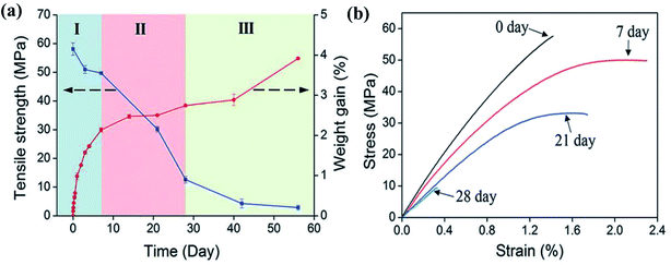 | ||
| Fig. 26 Tensile properties reduction of jute/PLA biocomposites after hygrothermal aging at 50 °C (a) tensile strength and weight gain as a function of immersion duration and (b) effect of aging degradation duration on stress–strain curve. This figure has been reproduced with permission from ref. 276, Elsevier, Copyright 2019 (License Number: 4759380095582). | ||
In the aging studies reported by Pothan et al.242 a comparison of aging severity on banana fibre composites was performed with different environmental conditions. It was found that water aging decreases the tensile strength of the samples the most with a 32% reduction, as compared to about 6% for thermal aging and 9% when exposed to sun and rain for six months. In order to simulate real life conditions; normal, distilled and salt water were also used to study the degradation behaviour of biofibre/polymer biocomposites. The water absorption of biocomposites have been reported to follow the order: salt water < normal water < distilled water281 and some different water condition studies follow: salt water < normal water < NaOH solution.282 Salt water shows the least water absorption rate, due to the existence of salt molecules. The salt particles reduce the water diffusion from the water medium to the fibre which further inhibits the water absorption rate of the fibres.282 The moisture absorption of curaua/glass and jute/glass-based hybrid biocomposites has also been found to be slower when immersed in sea water as compared to distilled water.283,284
The water absorption and saturation water content of the biofibre-based biocomposites could be reduced with the addition of a less hydrophilic material as a second filler. The hybridization approach of blending with more durable and hydrophobic synthetic glass fibres with biofibre is the most widely used and effective way to reduce the water absorption of the developed biocomposites.285 Hybridization of synthetic and natural fibres in biocomposites have been shown to yield better mechanical performance as compared to single sourced natural fibres.286 The idea of hybridization is to produce an optimal balance of performance in which the stronger component can compensate for the weakness of another component. The drawback of the high moisture absorption of biofibre-based biocomposites can also be resolved by incorporation of inert synthetic fibres. In a recent studies reported by Calabrese et al.287 the percentage of water absorption of the biofibre-based biocomposites can be reduced significantly by hybridization and lamination with glass fibre fabric in the outer layer to protect the biofibre fabric in the biocomposites for marine application purposes (Fig. 27 and 28). The decrease in the moisture absorption was observed with the increasing content of glass fibre in the hybrid biofibre–glass biocomposite system. In the studies conducted by Mishra et al.,288 the water absorption of pineapple leaf fibre and sisal fibre–polyester biocomposites were found to reduce approximately 5–7% at 24 hours after hybridization with glass fibre. Some other promising results have been confirmed in the hemp–glass,289 bamboo–glass,231,260 palmyra–glass,290 sisal/glass291 and jute/kenaf/E-glass281 biocomposites. This is due to the slower degradation and inertness of glass fibre in unfavorable water environments. In addition, the improvement and better retention of mechanical properties in biocomposites by hybridization of biofibre with synthetic fibres were also reported by many researchers.231,287 Therefore, the hybridization of biofibre with synthetic fibres is a workable strategy to enhance the mechanical properties as well as the durability of biofibre/polymer biocomposites. However, the goal to eliminate the use of synthetic fibres in polymer composites still remains. The improvement on the performance of biocomposites without relying on the help of synthetic fibres is another big challenge to breakthrough.
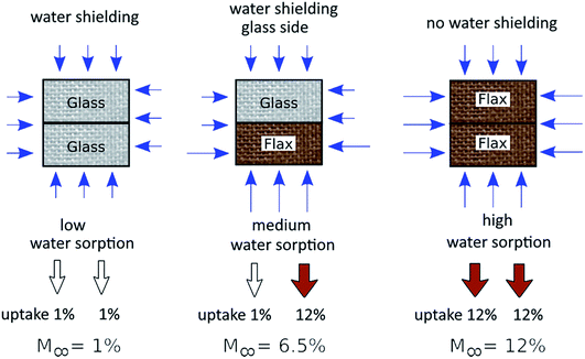 | ||
| Fig. 27 Glass–flax fabric hybrid biocomposites approach for water aging resistance for potential uses of biocomposites in marine applications. This figure has been reproduced with permission from ref. 287, Wiley, Copyright 2018 (License Number: 4707301287017). | ||
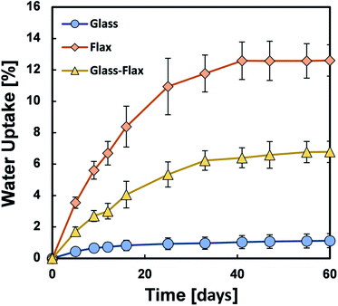 | ||
| Fig. 28 Enhanced water uptake resistance with the addition of glass fibre fabric in laminate flax biocomposites. This figure has been reproduced with permission from ref. 287, Wiley, Copyright 2018 (License Number: 4707301287017). | ||
The effect of different particles (TiO2, graphene nanoparticles and multiwall carbon nanotube (MWCNT)) on the hydrolytic degradation of reinforced PLA biocomposites were reported by Li et al.292 They found that the degradation rate of PLA was accelerated after the incorporation of these fillers except TiO2. This was mainly due to the imperfect interfacial interaction of the biocomposites, which are susceptible to moisture attacks. The hydrolytic degradation rate was decreased after undergoing surface treatment on MWCNT or an annealing process. Therefore, filler particle geometry, surface treatment and annealing treatment are greatly affecting the durability performance of the biocomposites.
Even though nanoclay can significantly improve the stiffness and thermal stability of composites, these nanocomposites seem to be undesirable when used in high humidity and high moisture environments. The water absorption and water diffusivity of PBS nanocomposites were reported to be higher than that of neat PBS after incorporation of OMMT organoclay.146 The authors attributed the finding to the presence of the hydrophilic nature of the octadecylamine groups in the OMMT structure. Neetu et al.293 observed an increase in the moisture absorption and swelling ratio of the clay/PCL biocomposite films while increasing the OMMT content. Mixed results have been reported on the hydrolytic degradation of clay/PLA biocomposites. The incorporation of nanoclay could accelerate the degradation of the aliphatic polyesters due to the catalytic effect of nanoclay and the presence of the hydroxyl groups of the silicate layers.294,295 While some authors reported the reverse effect due to the effective barrier properties of clay that further retarded the degradation.296
Norazlina et al.297 investigated the effect of MWCNT on the hygrothermal degradation of PLA biocomposites. They found that the addition of MWCNT increased the water absorption of PLA. The water absorption can be reduced through the treatment of CNT which can restrict the water diffusivity into the sample. In biomedical applications (in vitro degradation), it was reported that the rate of hydrolytic degradation (accelerated aging in NaOH at 50 °C solution) increased with the presence of hydroxyapatite (HA) nanoparticles in PLLA films.142 Several factors have been confirmed to have considerable effects on the hydrolytic degradation rate of PLA such as degree of crystallinity,298,299 hydrophilicity of the filler and its size,294,300 pH, and temperature of the solution.299 Amorphous PLA and its biocomposites exhibited a higher hydrolytic degradation rate than semicrystalline PLA and its biocomposites.299 This is due to the high water permeation rate in the amorphous domains.
The incorporation of biofibre with renewable bio-based poly(furfuryl alcohol) (PFA) presented interesting properties such as retaining mechanical properties after hygroscopic aging. The authors reported significantly lower water absorption of the kenaf/PFA biocomposites with a high retention in mechanical performance in comparison to other biofibre reinforced traditional polymers such as phenol and epoxy.301 In addition, the PFA coated woven flax fibre-reinforced phenolic biocomposites were found to be superior than biobased polyurethane and commercial biobased coatings in terms of moisture resistance and mechanical performance when subjected to environmental aging and water absorption.302 This can be attributed to the hydrophobic nature of PFA which decreased the moisture uptake.303
Besides chemical modification to alter the surface nature of the biocomposites, hydrophobic coatings show another promising approach to produce effective water resistant biocomposites. Particularly, PFA and polyurethane coatings possess high potential to be applied on biofibre/polymer composites to address the moisture absorption issue.304 The weight gain of the flax/PLLA biocomposites after water immersion testing was reduced by glazing it with an extra layer of PLLA coating.305 Lignin and lignin–phenol formaldehyde-based coatings have also been reported as an effective moisture resistant coating for bagasse biofibre-based biocomposites.306 Other hydrophobic coating such as silicone coating could be applied to minimize moisture absorption of the biocomposites.88 The enhanced water absorption resistance studies open up new ways for these eco-friendly materials to be used in marine applications.
8. Fatigue and creep related studies on biocomposites
Constant mechanical stress exerted on materials over a long duration can cause catastrophic failure at different service times. This type of durability test refers to structural durability where materials can withstand destruction under long-term cyclic stress from external forces. Structural durability includes special loads, wear, creep and fatigue loads. Fig. 29 shows the types of structural durability and their partitions.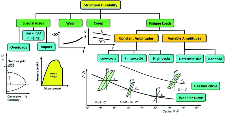 | ||
| Fig. 29 Types of structural durability and partitions. This figure has been redrawn and reproduced with permission from ref. 307, Elsevier, Copyright 2018 (License Number: 4785440892593). | ||
Fatigue is a process where materials experience repeated and continuous loading over time and leads to deterioration of its mechanical performance. Cyclic loading can be tested under three different modes, i.e. tension–tension mode, tension-compression mode and compression–compression mode. The sinusoidal waveform amplitudes of the three modes with their R-value are illustrated in Fig. 30. The fatigue properties of a material are usually presented with S–N curves (where S is the continuous stress exerted and N is the number of cycle it can sustain before fatigue failure, also called the fatigue life cycle) and the endurance or fatigue limit can be determined from the graph. As the number of cycles increase, fatigue stress decreases in a linear fashion. Under constant amplitude loading, the fatigue behaviour is described as a Wöhler curve, while at variable amplitude loading, the fatigue behaviour is described as a Gassner curve (Fig. 29). Each polymer exhibits different fatigue life. For example, PET and nylon do not show an endurance limit while other plastics like PP, polytetrafluoroethylene (PTFE) and polymethyl methacrylate (PMMA) exhibit a certain stress limit where failure will not occur in less than their endurance limit.99 A number of test variables and factors greatly affect the fatigue strength of plastic material including number of cycles, presence of stress concentrator, temperature, environment etc.
 | ||
| Fig. 30 Sinusoidal waveform amplitudes of the three cyclic loading modes (tension–tension, tension-compression and compression–compression) with their R-values. This figure has been reproduced with permission from ref. 308, Elsevier, Copyright 2013 (License Number: 4758380984963). | ||
Similar to other mechanical properties, the endurance limit of the polymers could be enhanced by reinforcement with different fibres and fillers. The studies of fatigue and creep of synthetic polymer composites are well reported in literature reviews. Most of the studies focused on composites reinforced with glass or carbon fibres as these composites are used in many structural applications, which are often exposed to cyclic stress and loading.309–313 On the other hand, fatigue and creep related studies on biopolymers and biocomposites are limited. Fatigue and creep studies on biocomposites should receive attention as the use of bioplastics and biocomposites have escalated significantly over years.
Liber-Kneć et al.314 investigated the accelerated fatigue behaviour of composites based on two biodegradable polymers i.e. thermoplastic starch (TPS) and PLA, both filled with 10 wt% short flax fibres. It was found that the TPS filled with flax fibres exhibited a lower fatigue strength, shortened fatigue life and higher susceptibility to cyclic creep than the neat polymer. On the other hand, a minor improvement on the fatigue strength of the PLA based composite was observed after the addition of flax fibres. According to the authors, the low fatigue strength of flax/TPS was mainly due to the lack of adhesion between the fibre and matrix, which leads to more intense crack initiation and propagation when subjected to both static and dynamic loading. Katogi et al.315 studied the fatigue behaviour of unidirectional jute/PLA biocomposites, they found that the fatigue strength of PLA and its biocomposites decreased with increasing number of cycles. They concluded that the fatigue strength of the biocomposites was strongly affected by the fatigue properties of the PLA. The crack initiation of the PLA matrix is the main dominating mechanism due to the brittleness of PLA. The cracks then propagated from the surface to the biofibre. In order to improve the fatigue life of PLA, it should be incorporated or blended with another ductile biopolymer such as PBS.
Unlike other durability behaviours discussed previously, the surface modification of the biofibre does not necessarily show improvement on the fatigue resistance of biocomposites. It has been reported that fibre treatment does not enhance the fatigue life of the biocomposites.316 A steeper slope of the S–N curve and accelerated fatigue degradation was observed on the alkali treated sisal fibre/polymer as compared to the untreated system.317 In addition, the treatment of the sisal fibre on the fatigue life was more pronounced for polyester than epoxy resin. Gassan and Bledzki318 reported that the fatigue properties of the NaOH-treated jute biofibre/epoxy biocomposites are poorer than the untreated jute biofibre/epoxy biocomposites. The shrinkage state of the biofibre after alkali treatment could be the main reason for the reduction of the fatigue resistance as well as dynamic modulus of the biocomposites. On the other hand, in a recent studies conducted by Ranganathan et al.,319 it was found that the addition of MAPP compatibilizer was able to further enhance the fatigue life strength (∼50%) of jute/viscose/PP hybrid biocomposites (Fig. 31).
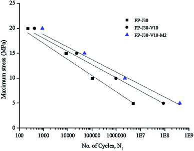 | ||
| Fig. 31 Fatigue life curve (S–N) of jute/PP biocomposites (PP-J30), jute/viscose/PP hybrid biocomposites (PP-J30-V10) and hybrid biocomposites with 2 wt% MAPP compatibilizer (PP-J30-V10-M2). This figure has been reproduced with permission from ref. 319, Elsevier, Copyright 2016 (License Number: 4758381224572). | ||
Furthermore, the fatigue resistance of the biocomposites was found to be lower when increasing the biofibre content in the biocomposites.318 In another study reported by Ray et al.,320 there was also no significant improvement on the fatigue strength of the jute/vinylester biocomposites when the jute fibres underwent 4 hours of alkali treatment. However, improvement on fatigue strength was observed when the jute fibres were treated for 8 hours. The fatigue strength was ranked as 8 hours alkali treated > untreated > 4 hours alkali treated respectively.
A comparative study on the fatigue behaviour of oil palm fruit bunch fibre/epoxy and CF/epoxy composites was reported by Kalam et al.321 It showed that a CF/epoxy composite exhibited higher fatigue resistance than an oil palm fruit bunch fibre/epoxy biocomposite (Fig. 32). Both composites showed typical fatigue behaviour where fatigue life was improved by reducing the maximum applied stress. The fatigue life of the oil palm fruit bunch fibre/epoxy was found to decrease significantly with increasing fibre volume ratio in the composite. The fatigue performance of biofibre/polymer biocomposites are still below par when compared to traditional synthetic fibres/polymer composites. Thwe and Liao244 reported that unreinforced PP has a longer fatigue life than bamboo fibre/PP and bamboo fibre/GF/PP hybrid biocomposites after one million cycles. In comparison to the biocomposites performance, the hybrid biocomposite showed better fatigue resistance than the monolithic bamboo fibre/PP biocomposites. Similarly, hybridization of hemp fibre with glass fibre showed enhancements in fatigue strength as compared to only hemp fibre biocomposites.322 Gassan323 reported that unidirectional biofibre-based biocomposites were less sensitive to fatigue induced damage as compared to woven biofibre-based biocomposites. In addition, biofibre strength (different type of fibres), higher fibre fraction and better fibre–matrix adhesion could result in higher critical loads to initiate fatigue damage and a decrease in crack propagation rate which leads to a better fatigue resistance. Table 7 summarizes some recent studies conducted on the fatigue performance of biocomposites.
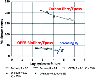 | ||
| Fig. 32 The logarithmic stress-life fatigue curves for traditional composites vs. biocomposites. This figure has been reproduced with permission from ref. 321, Elsevier, Copyright 2005 (License Number: 4707301450096). | ||
| Biocomposites | Fatigue test | Sample types | Main finding | Ref. |
|---|---|---|---|---|
| Flax/elium | Cyclic tension–tension fatigue, ASTM D3479 | Liquid infusion technique | The fatigue damage behaviour of the biocomposites can be determined with acoustic emission | 325 |
| In unidirectional configurations, flax/elium biocomposites exhibited good cyclic loading performance | ||||
| Hemp/epoxy | Tension–tension fatigue | Woven composite laminate [0°/90°] and [±45°] | [±45°] layups exhibited better fatigue strength than [0°/90°] | 324 |
| The details of fatigue mechanism and damage propagation were successfully examined with infrared camera and micro-CT | ||||
| Kenaf fibre/GF/polyester | Uniaxial tensile fatigue | Woven composite laminate | Hybridization of kenaf/glass fibres at optimal loading showed better fatigue strength than monolithic GF or kenaf-based composites | 326 |
| Surface heat generation during fatigue tests indicates loss of stiffness in the composites | ||||
| Kenaf/GF/polyester | Tension-compression cyclic loading, ISO 13003 (2003) | Sandwich composites, kenaf orientation: (1) non-woven random mat, (2) unidirectional twisted yarn, (3) plain-woven | Kenaf fibre orientation strongly affects the fatigue strength of the hybrid biocomposites | 327 |
| Biocomposites with unidirectional and woven kenaf fibres improved the fatigue degradation coefficient | ||||
| Jute/viscose/PP | Uniaxial tension–tension, ASTM D3479 M | Long fibre thermoplastics composites | Hybrid of jute and viscose biofibre (30![[thin space (1/6-em)]](https://www.rsc.org/images/entities/char_2009.gif) : :![[thin space (1/6-em)]](https://www.rsc.org/images/entities/char_2009.gif) 10) biocomposite shows three-times higher fatigue life than jute/PP biocomposite 10) biocomposite shows three-times higher fatigue life than jute/PP biocomposite |
319 |
| Addition of 2 wt% MAPP in the biocomposite further improves the fatigue life and fracture toughness | ||||
| Flax/epoxy | Tension–tension fatigue | Resin transfer moulding | Fibre architecture results in a significant effect on the fatigue behaviour of the biocomposites due to better fibre alignment and structure | 328 |
| Flax/unsaturated polyester (UP), jute/UP, hemp/UP, GF/UP | Tension–tension | Composite laminates, vacuum infusion technique | Plant fibre type, plant fibre quality, textile architecture and composite fibre content have low impact on fatigue strength coefficient | 308 |
| Absolute fatigue performance of GF composites is far superior to plant fibre biocomposites |
The complete damage development and analysis as well as fatigue mechanism of the biocomposites during fatigue testing can be monitored with different instrumentation. Davi et al.324 utilized acoustic emission monitoring, infrared and X-ray micro-tomography to analyze the fatigue mechanism of hemp/epoxy biocomposites. The heat generation and concentration zones allow the visualization of the damage propagation through infrared camera observations as shown in Fig. 33. Haggui et al.325 reported the fatigue damage mechanism of flax biocomposites using the acoustic emission technique.
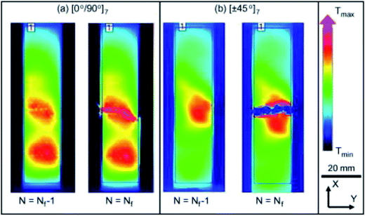 | ||
| Fig. 33 Variation of temperature on the sample surface measured by infrared camera during fatigue test, before and after failure (a) [0°/90°] laminate; (b) [±45°] laminate. This figure has been reproduced with permission from ref. 324, Elsevier, Copyright 2014 (License Number: 4758381396727). | ||
Creep test refers to a constant load application throughout the test duration while the strain is measured as a function of time. The viscoelastic behaviour of polymer composites is the result of their time-dependent properties. The result can be plotted in a strain–time curve. Typical creep curves exhibit three regions of deformation i.e. primary creep, secondary creep and tertiary creep. The tested samples changed from linear viscoelasticity to nonlinear viscoelasticity over time and with increasing stress. The relation of stress (σ) and strain (ε) at a given time duration (t) under a linear viscoelasticity region can be simply expressed as:
 | (6) |
The equation can be further resolved into creep compliance D(t) as a ratio of strain to stress at a given time (t) as:
 | (7) |
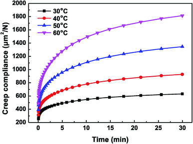 | ||
| Fig. 34 Creep compliance curve at different temperatures for wood flour/HDPE biocomposites. This figure has been reproduced with permission from ref. 332, Elsevier, Copyright 2017. | ||
Nuñez et al.333 studied the creep behaviour of PP/wood flour biocomposites with different variables of wood flour loading, compatibilizer and temperature. The creep deformation was found to reduce when increasing wood flour content (Fig. 35) (except for >60% where the agglomeration and filler–filler interaction become dominant) and with appropriate amount of MAPP compatibilizer due to improved compatibility between phases.333 The environment temperature also plays an important role in the creep behaviour of the biocomposites as the materials soften when temperatures rise. In addition, the creep behaviour of the PP/wood flour biocomposite was successfully fitted with Burger's model and power law equation based on the linear viscoelastic behaviour of the biocomposites as shown in Fig. 35. Acha et al.334 studied and modeled the creep recovery behaviour of jute/PP biocomposites. They found that the creep deformation decreases as the jute biofibre content increases. However, only marginal increase was observed when the jute content was above 25 wt%. In addition, the compatibilizer and coupling agent was found to be beneficial in enhancing creep resistance of biocomposites due to the improved interface adhesion.334 Lower creep deformation was reported in flax fibre/epoxy biocomposites after surface treatment with silanization, alkalization and acetylation.335 The modification of wood-based biocomposites with a silane cross-linked reaction has been proved to be an effective way to improve the creep properties.336 The creep rate showed 50% lower as compared to the non-crosslinked biocomposites. In addition, the non-recovery deformation after recovering was reduced to 0.2% after crosslinking from 0.7% for the non-crosslinked samples.
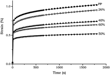 | ||
| Fig. 35 The creep curves of neat PP and PP/wood flour biocomposites with different wood flour concentration. The continuous lines correspond to the best fitting of the Burgers model with 4 parameters. This figure has been reproduced with permission from ref. 333, Wiley, Copyright 2004 (License Number: 4707310091424). | ||
The creep performance of the biocomposites is dependent on the orientation of biofibres.18 Other alternative methods have been reported to estimate the creep behaviour of biocomposites such as nanoindentation.195 The creep behaviour can be predicted by analyzing the deformation and recovery of the polymer upon nanoindentation for a specific holding duration at a constant load.
9. Conclusions and future perspectives
Polymer composites are an important class of lightweight materials which are appropriate for critical structural applications such as aircraft and automotive components. Their long-term degradation behaviour under exposure to various environmental conditions are crucial to determining their service lifetime. The present review covered studies conducted and reported on biocomposites for their long-term durability performance. Although traditional fibres/polymer composites possess several advantages over biobased composites in terms of mechanical performance and durability such as fatigue strength and moisture absorption, they also have limitations like high density and cost, poor recyclability, disposal problems, environmental and sustainability issues. The tremendous growth of biobased composites (biocomposites) research and the expansion of their applications as endeavors from the government, scientists and industries have justified their significance in the modern society for a better future. Although some biocomposites are on par with traditional petro-based composites in terms of mechanical performance, the majority of them are still underperforming when long-term durability is concerned. The durability performance of biocomposites can be enhanced considerably with proper biofiller selection and surface modification. Effective exterior surface coating has shown promising results in slowing down the weathering degradation of biocomposites.Biobased fibre (biofibre) as a renewable reinforcement to develop biocomposites has dominated the market for noncritical applications for the past two decades. Other sustainable materials from biomass, industrial co-products, waste stream materials, and recycled materials can also be considered for use as both the matrix and the reinforcement to make biocomposites. These biocomposite materials should be paid attention to in order to improve their performance for future potential bioproduct fabrication and applications. The utilizations of these biobased and waste stream materials can minimize the use of non-renewable resources and can lead to better use of resources and more sustainable development. Biosourced carbon, chitosan and other biobased nanocomposites could be potential alternatives to biofibre. The use of biocarbon offers some advantages over biofibre such as high processing windows (can be processed with engineering plastics such as nylon 6, nylon 6,6, PET, etc.), high degradation temperatures (>250 °C), low variation in properties (only carbon structure), no odor and black in color (∼75% of cars contain black interior parts).
Different processing techniques (compression moulding, injection moulding, etc.) and biofillers use when producing biocomposites could yield significant differences in terms of durability and performance. The UV degradation of biofibre-based biocomposites can be reduced by hybridization with other synthetic fibres and with the addition of small amount of UV-stabilizers. Further research is needed in order to improve their durability performance to compete with traditionally used composite materials.
Despite the good mechanical strength as is, the hydrophilic nature of biofibre surfaces causes differences in polarity between the fibres and the polymer matrix. In addition, the high water absorption remains a challenge, which limits its applications in high humidity environments. Composites are complex materials involving two or more components present in a system. The interactions and bonding mechanism between each component are crucial in obtaining good durability performance. Higher oxidation and degradation rates were observed as compared to neat polymers due to imperfection interfaces of the composites. Biocomposites are less susceptible to be attacked and degraded by oxygen and moisture when established bonding between phases is achieved. Therefore, the modification of either filler or matrix components through chemical treatment or coating for enhancing the biocomposites interface should be paid more attention to, in order to improve their durability performance.
Fatigue and creep studies on biocomposites are very limited. These tests are very important to recognize the basic cyclic failure behaviours of the newly invented biocomposites for future commercialization purposes. Biocomposites still lack in fatigue and creep when compared to conventional composites. The incorporation of biofibres into polymers with proper techniques could improve the fatigue life as well as the creep resistance. There is still improvement in this area needed for biocomposites to be able to perform at a high-level for advanced applications. In addition, the fatigue and creep performance of biocomposites can be enhanced further by proper surface treatment, stacking sequence and configuration, and hybridization with synthetic fibres.
Studies on different aging mechanisms when subjected to different service environments on biocomposite behaviour are needed for continuous improvement of these materials. Researchers have revealed that computational modelling of aging outcomes is a promising solution to predict the behaviour of biocomposites. This can help in finding appropriate applications for biocomposites based on their lifetime predictions. However, the modeling of aging process is still very dependent on many factors other than environmental conditions such as fibre/filler dispersion and the type of biofibre used.
With growing concern over environmental pollution and global sustainable development, biocomposites made from various renewable resources are the materials of the future. Furthermore, the development of biocomposites should not solely focus on reducing cost and partial replacement of traditional composites; rather it should include the progression and development of high performance and durable engineered fully biobased and biodegradable biocomposites for possible mass industrialization in the future. With improvements in durability studies on biocomposites, there is a huge potential for these materials to succeed in commercial markets in the future. With the societal shift into use of more sustainable plastics and composites, the desirability of biocomposites will exceed the current level of implementation, and further development and modification would be required to meet or exceed the expectations that traditional composites have. These areas could include advanced aerospace, automotive and engineering applications, where biocomposite development is not up to standard at this time.
Conflicts of interest
There are no conflicts to declare.Acknowledgements
The authors acknowledge the financial support from Ontario Research Fund, Research Excellence Program; Round-7 (ORF-RE07) from the Ontario Ministry of Research Innovation and Science (MRIS) (Project # 052644 and 052665); the Ontario Ministry of Agriculture, Food and Rural Affairs (OMAFRA)-Canada/University of Guelph-Bioeconomy for Industrial Uses Research Program Theme (Project # 030176, 030332 and 030331); OMAFRA-University of Guelph Gryphon’s LAAIR Program (Project # 298636) the Agriculture and Agri-Food Canada (AAFC), through Bioindustrial Innovation Canada (BIC) Bioproducts AgSci Cluster Program (Project # 054015), Maple Leaf Food, Canada (Project # 054449), BMO Canada (Project # 800148) and the Natural Sciences and Engineering Research Council (NSERC) Canada – Discovery Grants (Project # 401111 and 400320).References
- O. E. Ogunmakinde, Recycling, 2019, 4, 27 CrossRef.
- P. Ghisellini, C. Cialani and S. Ulgiati, J. Clean. Prod., 2016, 114, 11–32 CrossRef.
- Y. Geng and B. Doberstein, Int. J. Sustain. Dev. World Ecol., 2008, 15, 231–239 CrossRef.
- J. Korhonen, A. Honkasalo and J. Seppälä, Ecol. Econ., 2018, 143, 37–46 CrossRef.
- B. Su, A. Heshmati, Y. Geng and X. Yu, J. Clean. Prod., 2013, 42, 215–227 CrossRef.
- F. Zhijun and Y. Nailing, Sustain. Sci., 2007, 2, 95–101 CrossRef.
- K. Formela, Ł. Zedler, A. Hejna and A. Tercjak, Express Polym. Lett., 2018, 12, 24–57 CrossRef.
- H. Nakajima, P. Dijkstra and K. Loos, Polymers, 2017, 9, 523 CrossRef PubMed.
- A. K. Mohanty, S. Vivekanandhan, J.-M. Pin and M. Misra, Science, 2018, 362, 536–542 CrossRef CAS PubMed.
- F. M. AL-Oqla and M. A. Omari, in Green Biocomposites: Manufacturing and Properties, ed. M. Jawaid, S. M. Sapuan and O. Y. Alothman, Springer International Publishing, Cham, 2017, pp. 13–29, DOI:10.1007/978-3-319-46610-1_2.
- A. K. Mohanty, M. Misra and G. Hinrichsen, Macromol. Mater. Eng., 2000, 276–277, 1–24 CrossRef.
- T. P. Schlöesser, in Natural Fibers, Plastics and Composites, ed. F. T. Wallenberger and N. E. Weston, Springer US, Boston, MA, 2004, pp. 275–285, DOI:10.1007/978-1-4419-9050-1_15.
- O. Faruk, A. K. Bledzki, H.-P. Fink and M. Sain, Macromol. Mater. Eng., 2014, 299, 9–26 CrossRef CAS.
- D. K. Platt, Engineering and high performance plastics market report: a Rapra market report, iSmithers Rapra Publishing, 2003 Search PubMed.
- G. Koronis, A. Silva and M. Fontul, Composites, Part B, 2013, 44, 120–127 CrossRef CAS.
- D. B. Dittenber and H. V. S. GangaRao, Composites, Part A, 2012, 43, 1419–1429 CrossRef.
- A. D. La Rosa, G. Recca, J. Summerscales, A. Latteri, G. Cozzo and G. Cicala, J. Clean. Prod., 2014, 74, 135–144 CrossRef CAS.
- S. A. Miller, J. Clean. Prod., 2018, 198, 612–623 CrossRef CAS.
- W. Brouwer, SAMPE J., 2000, 36, 18–23 CAS.
- A. K. Mohanty, M. Misra and L. T. Drzal, Compos. Interfac., 2001, 8, 313–343 CrossRef CAS.
- D. N. Saheb and J. P. Jog, Adv. Polym. Technol., 1999, 18, 351–363 CrossRef CAS.
- L. Mohammed, M. N. M. Ansari, G. Pua, M. Jawaid and M. S. Islam, Int. J. Polym. Sci., 2015, 2015, 243947 Search PubMed.
- K. L. Pickering, M. G. A. Efendy and T. M. Le, Composites, Part A, 2016, 83, 98–112 CrossRef CAS.
- O. Faruk, A. K. Bledzki, H.-P. Fink and M. Sain, Prog. Polym. Sci., 2012, 37, 1552–1596 CrossRef CAS.
- F. P. La Mantia and M. Morreale, Composites, Part A, 2011, 42, 579–588 CrossRef.
- S. K. Ramamoorthy, M. Skrifvars and A. Persson, Polym. Rev., 2015, 55, 107–162 CrossRef CAS.
- H. Ku, H. Wang, N. Pattarachaiyakoop and M. Trada, Composites, Part B, 2011, 42, 856–873 CrossRef.
- S. V. Joshi, L. T. Drzal, A. K. Mohanty and S. Arora, Composites, Part A, 2004, 35, 371–376 CrossRef.
- P. Wambua, J. Ivens and I. Verpoest, Compos. Sci. Technol., 2003, 63, 1259–1264 CrossRef CAS.
- R. Malkapuram, V. Kumar and Y. S. Negi, J. Reinf. Plast. Compos., 2009, 28, 1169–1189 CrossRef CAS.
- H. M. Akil, M. F. Omar, A. A. M. Mazuki, S. Safiee, Z. A. M. Ishak and A. Abu Bakar, Mater. Des., 2011, 32, 4107–4121 CrossRef CAS.
- L. Yan, N. Chouw and K. Jayaraman, Composites, Part B, 2014, 56, 296–317 CrossRef CAS.
- F. M. Al-Oqla, S. M. Sapuan, T. Anwer, M. Jawaid and M. E. Hoque, Synth. Met., 2015, 206, 42–54 CrossRef CAS.
- Z. N. Azwa, B. F. Yousif, A. C. Manalo and W. Karunasena, Mater. Des., 2013, 47, 424–442 CrossRef CAS.
- Y. Xie, C. A. S. Hill, Z. Xiao, H. Militz and C. Mai, Composites, Part A, 2010, 41, 806–819 CrossRef.
- J. George, M. S. Sreekala and S. Thomas, Polym. Eng. Sci., 2001, 41, 1471–1485 CrossRef CAS.
- S. Kalia, B. S. Kaith and I. Kaur, Polym. Eng. Sci., 2009, 49, 1253–1272 CrossRef CAS.
- M. J. John and R. D. Anandjiwala, Polym. Compos., 2008, 29, 187–207 CrossRef CAS.
- X. Li, L. G. Tabil and S. Panigrahi, J. Polym. Environ., 2007, 15, 25–33 CrossRef.
- M. M. Kabir, H. Wang, K. T. Lau and F. Cardona, Composites, Part B, 2012, 43, 2883–2892 CrossRef CAS.
- F. Ahmad, H. S. Choi and M. K. Park, Macromol. Mater. Eng., 2015, 300, 10–24 CrossRef CAS.
- S. Nunna, P. R. Chandra, S. Shrivastava and A. Jalan, J. Reinf. Plast. Compos., 2012, 31, 759–769 CrossRef CAS.
- N. Saba, P. Tahir and M. Jawaid, Polymers, 2014, 6, 2247–2273 CrossRef.
- S. Chapple and R. Anandjiwala, J. Thermoplast. Compos. Mater., 2010, 23, 871–893 CrossRef CAS.
- J. Holbery and D. Houston, JOM, 2006, 58, 80–86 CrossRef CAS.
- M. R. Sanjay, G. R. Arpitha and B. Yogesha, Mater. Today: Proc., 2015, 2, 2959–2967 Search PubMed.
- U. Nirmal, J. Hashim and M. M. H. Megat Ahmad, Tribol. Int., 2015, 83, 77–104 CrossRef CAS.
- E. Omrani, P. L. Menezes and P. K. Rohatgi, Eng. Sci. Technol. Int. J., 2016, 19, 717–736 CrossRef.
- N. Chand and M. Fahim, Tribology of natural fiber polymer composites, Elsevier, 2008 Search PubMed.
- B. P. Chang, H. Md Akil and M. H. Zamri, in Green Biocomposites: Manufacturing and Properties, ed. M. Jawaid, S. M. Sapuan and O. Y. Alothman, Springer International Publishing, Cham, 2017, pp. 149–179, DOI:10.1007/978-3-319-46610-1_7.
- C. W. Chin and B. F. Yousif, Wear, 2009, 267, 1550–1557 CrossRef CAS.
- B. Bax and J. Müssig, Compos. Sci. Technol., 2008, 68, 1601–1607 CrossRef CAS.
- D. Plackett, T. Løgstrup Andersen, W. Batsberg Pedersen and L. Nielsen, Compos. Sci. Technol., 2003, 63, 1287–1296 CrossRef CAS.
- A. P. Mathew, K. Oksman and M. Sain, J. Appl. Polym. Sci., 2005, 97, 2014–2025 CrossRef CAS.
- R. Gunti, A. V. Ratna Prasad and A. V. S. S. K. S. Gupta, Polym. Compos., 2018, 39, 1125–1136 CrossRef CAS.
- M. D. H. Beg and K. L. Pickering, Polym. Degrad. Stab., 2008, 93, 1939–1946 CrossRef CAS.
- T. Gates, in Ageing of Composites, ed. R. Martin, Woodhead Publishing, 2008, pp. 3–33, DOI:10.1533/9781845694937.1.3.
- J. M. Corum, R. L. Battiste, M. B. Ruggles and W. Ren, Compos. Sci. Technol., 2001, 61, 1083–1095 CrossRef CAS.
- C. Taylor, A. Amiri, D. Webster and C. Ulven, presented in part at the CAMX The Composites and Advanced Materials Conference, Anaheim, California, 2016 Search PubMed.
- W. Smitthipong, R. Chollakup and M. Nardin, Bio-Based Composites for High-Performance Materials: From Strategy to Industrial Application, CRC Press, 2014 Search PubMed.
- R. Chollakup, W. Kongtad and F. Delor-Jestin, Photo and thermo-degradation of polyethylene/palm fibre composites, in 51. Kasetsart University Annual Conference, Bangkok, Thailand, 2013, pp. 68–76 Search PubMed.
- L. Markovičová and V. Zatkalíková, IOP Conf. Ser.: Mater. Sci. Eng., 2019, 465, 012004 Search PubMed.
- M. Mohamed, M. Johnson and F. Taheri, Open J. Compos. Mater., 2019, 9, 145–163 CrossRef CAS.
- H. Parvatareddy, J. Z. Wang, D. A. Dillard, T. C. Ward and M. E. Rogalski, Compos. Sci. Technol., 1995, 53, 399–409 CrossRef CAS.
- H. Kaczmarek, D. Ołdak, P. Malanowski and H. Chaberska, Polym. Degrad. Stab., 2005, 88, 189–198 CrossRef CAS.
- J. Petersen, A review of the fundamentals of asphalt oxidation, Washington, DC, 2009 Search PubMed.
- T. A. Kumar, I. J. S. Sandeep, M. R. Nivitha, V. Chowdary and J. M. Krishnan, Arabian J. Sci. Eng., 2019, 44, 8429–8437 CrossRef CAS.
- F. P. La Mantia and N. T. Dintcheva, Plast., Rubber Compos., 2004, 33, 184–186 CrossRef CAS.
- M. Gardette, S. Thérias, J.-L. Gardette, M. Murariu and P. Dubois, Polym. Degrad. Stab., 2011, 96, 616–623 CrossRef CAS.
- S. Bocchini, K. Fukushima, A. D. Blasio, A. Fina, A. Frache and F. Geobaldo, Biomacromolecules, 2010, 11, 2919–2926 CrossRef CAS PubMed.
- Y. Chen, N. Stark, M. Tshabalala, J. Gao and Y. Fan, Materials, 2016, 9, 610 CrossRef PubMed.
- M. Diagne, M. Guèye, A. Dasilva and A. Tidjani, J. Appl. Polym. Sci., 2007, 105, 3789–3793 CrossRef.
- A. Tidjani, J. Appl. Polym. Sci., 1997, 64, 2497–2503 CrossRef CAS.
- X. Colin, C. Marais, J. L. Cochon and J. Verdu, Kinetic modelling of weight changes during the isothermal oxidative ageing, Recent Developments in Durability Analysis of Composite Systems, ed. H. Dardon, H. Fukuda, K. L. Reifsnider and G. Verchery, 1999, pp. 49–54 Search PubMed.
- A. Torikai, H. Shirakawa, S. Nagaya and K. Fueki, J. Appl. Polym. Sci., 1990, 40, 1637–1646 CrossRef CAS.
- F. P. La Mantia, N. T. Dintcheva, V. Malatesta and F. Pagani, Polym. Degrad. Stab., 2006, 91, 3208–3213 CrossRef CAS.
- V. Mittal, T. Akhtar, G. Luckachan and N. Matsko, Colloid Polym. Sci., 2015, 293, 573–585 CrossRef CAS.
- X. Zuo, K. Zhang, Y. Lei, S. Qin, Z. Hao and J. Guo, J. Appl. Polym. Sci., 2014, 131, 39594 Search PubMed.
- D. Fromageot, A. Roger and J. Lemaire, Die Angewandte Makromolekulare Chemie: Applied Macromolecular Chemistry and Physics, 1989, vol. 170, pp. 71–85 Search PubMed.
- W. Dong and P. Gijsman, Polym. Degrad. Stab., 2010, 95, 1054–1062 CrossRef CAS.
- M. C. Celina, Polym. Degrad. Stab., 2013, 98, 2419–2429 CrossRef CAS.
- A. A. Mohamed, V. L. Finkenstadt and D. E. Palmquist, J. Appl. Polym. Sci., 2008, 107, 898–908 CrossRef CAS.
- C. M. d. Santos, B. C. d. Silva, E. H. Backes, L. S. Montagna, L. A. Pessan and F. R. Passador, Mater. Res., 2018, 21, e20180320 Search PubMed.
- Y. Shu, L. Ye and T. Yang, J. Appl. Polym. Sci., 2008, 110, 945–957 CrossRef CAS.
- M. Ahmad Sawpan, M. R. Islam, M. D. H. Beg and K. Pickering, J. Polym. Environ., 2019, 27, 942–955 CrossRef CAS.
- H. Tsuji and M. Sawada, J. Appl. Polym. Sci., 2010, 116, 1190–1196 CAS.
- Y. Li and X. Susan Sun, J. Appl. Polym. Sci., 2011, 121, 589–597 CrossRef CAS.
- C. M. Chan, L.-J. Vandi, S. Pratt, P. Halley, D. Richardson, A. Werker and B. Laycock, Eur. Polym. J., 2018, 98, 337–346 CrossRef CAS.
- R. Seldén, B. Nyström and R. Långström, Polym. Compos., 2004, 25, 543–553 CrossRef.
- B. F. Abu-Sharkh and H. Hamid, Polym. Degrad. Stab., 2004, 85, 967–973 CrossRef CAS.
- P. Cerruti and C. Carfagna, Polym. Degrad. Stab., 2010, 95, 2405–2412 CrossRef CAS.
- D. Lévêque, A. Schieffer, A. Mavel and J.-F. Maire, Compos. Sci. Technol., 2005, 65, 395–401 CrossRef.
- M. Strlič and J. Kolar, Ageing and stabilisation of paper, National and University Library Ljubljana, 2005 Search PubMed.
- K. Buffum, H. Pacheco and S. Shivkumar, Polym.-Plast. Technol. Eng., 2015, 54, 506–514 CrossRef CAS.
- R. Lehrle, D. Atkinson, S. Cook, P. Gardner, S. Groves, R. Hancox and G. Lamb, Polym. Degrad. Stab., 1993, 42, 281–291 CrossRef CAS.
- C. M. Clemons and R. E. Ibach, For. Prod. J., 2004, 54(4), 50–57 Search PubMed.
- N. M. Stark, L. M. Matuana and C. M. Clemons, J. Appl. Polym. Sci., 2004, 93, 1021–1030 CrossRef CAS.
- B. Dao, J. Hodgkin, J. Krstina, J. Mardel and W. Tian, J. Appl. Polym. Sci., 2010, 115, 901–910 CrossRef CAS.
- S. Lampman, Characterization and failure analysis of plastics, Asm International, 2003 Search PubMed.
- R. S. C. Woo, Y. Chen, H. Zhu, J. Li, J.-K. Kim and C. K. Y. Leung, Compos. Sci. Technol., 2007, 67, 3448–3456 CrossRef CAS.
- M. Diagne, M. Guèye, L. Vidal and A. Tidjani, Polym. Degrad. Stab., 2005, 89, 418–426 CrossRef CAS.
- D. Kockott, Weathering, Handbook of polymer testing: physical methods, Marcel Dekker, CRC Press, New York, 1999 Search PubMed.
- G.-H. Koo and J. Jang, Fibers Polym., 2008, 9, 674–678 CrossRef CAS.
- B. Gewert, M. M. Plassmann and M. MacLeod, Environ. Sci.: Processes Impacts, 2015, 17, 1513–1521 RSC.
- E. Yousif and R. Haddad, SpringerPlus, 2013, 2, 398 CrossRef PubMed.
- B. Singh and N. Sharma, Polym. Degrad. Stab., 2008, 93, 561–584 CrossRef CAS.
- N. T. Dintcheva and F. P. La Mantia, Polym. Degrad. Stab., 2007, 92, 630–634 CrossRef CAS.
- I. Menapace and E. Masad, J. Microsc., 2016, 263, 341–356 CrossRef CAS.
- A. Copinet, C. Bertrand, S. Govindin, V. Coma and Y. Couturier, Chemosphere, 2004, 55, 763–773 CrossRef CAS PubMed.
- G. Gorrasi, C. Milone, E. Piperopoulos, M. Lanza and A. Sorrentino, Appl. Clay Sci., 2013, 71, 49–54 CrossRef CAS.
- R. Pucciariello, V. Villani, C. Bonini, M. D'Auria and T. Vetere, Polymer, 2004, 45, 4159–4169 CrossRef CAS.
- N. Hongsriphan, K. Jeensikhong, K. Sornnuwat and N. Yaemyen, J. Bionic Eng., 2018, 15, 1075–1086 CrossRef.
- S. Zhu, Y. Chen, Y. Tang, Q. Li, B. Zhong, X. Zeng, D. Xie, Z. Jia and D. Jia, Polym. Compos., 2019, 40, 4154–4161 CrossRef CAS.
- I. Spiridon, R. N. Darie and H. Kangas, Composites, Part B, 2016, 92, 19–27 CrossRef CAS.
- I. Spiridon, K. Leluk, A. M. Resmerita and R. N. Darie, Composites, Part B, 2015, 69, 342–349 CrossRef CAS.
- R. Chollakup, H. Askanian and F. Delor-Jestin, J. Thermoplast. Compos. Mater., 2017, 30, 174–195 CrossRef CAS.
- S. Agustin-Salazar, N. Gamez-Meza, L. Á. Medina-Juárez, M. Malinconico and P. Cerruti, ACS Sustainable Chem. Eng., 2017, 5, 4607–4618 CrossRef CAS.
- M. Zaki Abdullah, Y. Dan-mallam and P. S. M. Megat Yusoff, Adv. Mater. Sci. Eng., 2013, 2013, 1–8 CrossRef.
- D. Friedrich, Case Studies in Construction Materials, 2018, 9, e00196 CrossRef.
- L. Soccalingame, D. Perrin, J. C. Bénézet, S. Mani, F. Coiffier, E. Richaud and A. Bergeret, Polym. Degrad. Stab., 2015, 120, 313–327 CrossRef CAS.
- J. Nicholson, The chemistry of polymers, Royal Society of Chemistry, 2017 Search PubMed.
- S. Tian, Y. Luo, J. Chen, H. He, Y. Chen and Z. Ling, Materials, 2019, 12, 876 CrossRef CAS PubMed.
- O. Mysiukiewicz, M. Barczewski, K. Skórczewska, J. Szulc and A. Kloziński, Polymers, 2019, 11, 1495 CrossRef CAS PubMed.
- L. Techawinyutham, S. Siengchin, R. Dangtungee and J. Parameswaranpillai, Composites, Part B, 2019, 175, 107108 CrossRef CAS.
- G. Mehta, A. K. Mohanty, L. T. Drzal, D. P. Kamdem and M. Misra, J. Polym. Environ., 2006, 14, 359–368 CrossRef CAS.
- S. Lv, X. Liu, J. Gu, Y. Jiang, H. Tan and Y. Zhang, Constr. Build. Mater., 2017, 144, 525–531 CrossRef CAS.
- C. Kaynak and B. Sarı, Appl. Clay Sci., 2016, 121–122, 86–94 CrossRef CAS.
- C. Kaynak and I. Kaygusuz, J. Compos. Mater., 2016, 50, 365–375 CrossRef CAS.
- D. Van Cong, N. T. T. Trang, N. V. Giang, T. D. Lam and T. Hoang, J. Electron. Mater., 2016, 45, 2536–2546 CrossRef.
- Y. Peng, X. Guo, J. Cao and W. Wang, Polym. Compos., 2017, 38, 1194–1205 CrossRef CAS.
- V. D. Nguyen, T. T. Nguyen, A. Zhang, J. Hao and W. Wang, J. For. Res., 2019 DOI:10.1007/s11676-019-00890-4.
- D. Rasouli, N. T. Dintcheva, M. Faezipour, F. P. La Mantia, M. R. Mastri Farahani and M. Tajvidi, Polym. Degrad. Stab., 2016, 133, 85–91 CrossRef CAS.
- D. S. Bajwa, S. G. Bajwa and G. A. Holt, Polym. Degrad. Stab., 2015, 120, 212–219 CrossRef CAS.
- C. Taylor, A. Amiri, A. Paramarta, C. Ulven and D. Webster, Mater. Des., 2017, 113, 17–26 CrossRef CAS.
- M.-J. Le Guen, V. Thoury-Monbrun, J. M. Castellano Roldán and S. J. Hill, J. Polym. Environ., 2017, 25, 419–426 CrossRef CAS.
- G. H. Yew, W. S. Chow, Z. A. Mohd Ishak and A. M. Mohd Yusof, J. Elastomers Plastics, 2009, 41, 369–382 CrossRef CAS.
- L. Zaidi, M. Kaci, S. Bruzaud, A. Bourmaud and Y. Grohens, Polym. Degrad. Stab., 2010, 95, 1751–1758 CrossRef CAS.
- B. Singh, M. Gupta and A. Verma, Compos. Sci. Technol., 2000, 60, 581–589 CrossRef CAS.
- S. Joseph, Z. Oommen and S. Thomas, J. Appl. Polym. Sci., 2006, 100, 2521–2531 CrossRef CAS.
- M. S. Islam, K. L. Pickering and N. J. Foreman, Polym. Degrad. Stab., 2010, 95, 59–65 CrossRef CAS.
- M. F. Gonzalez, R. A. Ruseckaite and T. R. Cuadrado, J. Appl. Polym. Sci., 1999, 71, 1223–1230 CrossRef CAS.
- C. Delabarde, C. J. G. Plummer, P.-E. Bourban and J.-A. E. Månson, Polym. Degrad. Stab., 2011, 96, 595–607 CrossRef CAS.
- M. Mohammed, A. R. Rozyanty, B. O. Beta, T. Adam, A. F. Osman, I. A. S. Salem, O. S. Dahham, M. N. Al-Samarrai and A. M. Mohammed, J. Phys.: Conf. Ser., 2017, 908, 012004 CrossRef.
- A. Rozyanty, M. Mohammed, L. Musa, S. Shahnaz and A. Zuliahani, AIP Conf. Proc., 2017, 1835, 020015 CrossRef.
- M. Pluta, A. Galeski, M. Alexandre, M.-A. Paul and P. Dubois, J. Appl. Polym. Sci., 2002, 86, 1497–1506 CrossRef CAS.
- Y. J. Phua, W. S. Chow and Z. A. Mohd Ishak, J. Thermoplast. Compos. Mater., 2010, 24, 133–151 CrossRef.
- A. Tidjani and C. A. Wilkie, Polym. Degrad. Stab., 2001, 74, 33–37 CrossRef CAS.
- H. Qin, C. Zhao, S. Zhang, G. Chen and M. Yang, Polym. Degrad. Stab., 2003, 81, 497–500 CrossRef CAS.
- J. M. Sloan and P. Patterson, Mechanisms of photo degradation for layered silicate-polycarbonate nanocomposites, Army Research Lab Aberdeen Proving Ground Md Weapons And Materials Research Directorate, 2005 Search PubMed.
- S. Morlat-Therias, E. Fanton, J.-L. Gardette, N. T. Dintcheva, F. P. La Mantia and V. Malatesta, Polym. Degrad. Stab., 2008, 93, 1776–1780 CrossRef CAS.
- S. Morlat, B. Mailhot, D. Gonzalez and J.-L. Gardette, Chem. Mater., 2004, 16, 377–383 CrossRef CAS.
- S. Morlat-Therias, B. Mailhot, J.-L. Gardette, C. Da Silva, B. Haidar and A. Vidal, Polym. Degrad. Stab., 2005, 90, 78–85 CrossRef CAS.
- Š. Chmela, A. Kleinová, A. Fiedlerová, E. Borsig, D. Kaempfer, R. Thomann and R. Mülhaupt, J. Macromol. Sci., Part A: Pure Appl.Chem., 2005, 42, 821–829 CrossRef.
- H. Qin, Z. Zhang, M. Feng, F. Gong, S. Zhang and M. Yang, J. Polym. Sci., Part B: Polym. Phys., 2004, 42, 3006–3012 CrossRef CAS.
- M.-F. Huang, J.-G. Yu and X.-F. Ma, Polymer, 2004, 45, 7017–7023 CrossRef CAS.
- M. Huang and J. Yu, J. Appl. Polym. Sci., 2006, 99, 170–176 CrossRef CAS.
- S. I. Marras, I. Zuburtikudis and C. Panayiotou, Eur. Polym. J., 2007, 43, 2191–2206 CrossRef CAS.
- N. Najafi, M. C. Heuzey, P. J. Carreau and P. M. Wood-Adams, Polym. Degrad. Stab., 2012, 97, 554–565 CrossRef CAS.
- S. J. A. Hocker, N. V. Hudson-Smith, P. T. Smith, C. H. Komatsu, L. R. Dickinson, H. C. Schniepp and D. E. Kranbuehl, Polymer, 2017, 126, 248–258 CrossRef CAS.
- K.-Y. Lee, Y. Aitomäki, L. A. Berglund, K. Oksman and A. Bismarck, Compos. Sci. Technol., 2014, 105, 15–27 CrossRef CAS.
- E. Luiz de Paula, V. Mano and F. V. Pereira, Polym. Degrad. Stab., 2011, 96, 1631–1638 CrossRef CAS.
- K. M. Z. Hossain, I. Ahmed, A. J. Parsons, C. A. Scotchford, G. S. Walker, W. Thielemans and C. D. Rudd, J. Mater. Sci., 2012, 47, 2675–2686 CrossRef CAS.
- M. J. Mochane, T. C. Mokhena, T. H. Mokhothu, A. Mtibe, E. R. Sadiku, S. S. Ray, I. D. Ibrahim and O. O. Daramola, Express Polym. Lett., 2019, 13, 159–198 CrossRef CAS.
- I. Turku and T. Kärki, Composites, Part A, 2016, 81, 305–312 CrossRef CAS.
- I. Grigoriadou, E. Pavlidou, K. M. Paraskevopoulos, Z. Terzopoulou and D. N. Bikiaris, Polym. Degrad. Stab., 2018, 153, 23–36 CrossRef CAS.
- N. Sgriccia, M. C. Hawley and M. Misra, Composites, Part A, 2008, 39, 1632–1637 CrossRef.
- A. S. Singha and R. K. Rana, Mater. Des., 2012, 41, 289–297 CrossRef CAS.
- K. C. Manikandan Nair, S. Thomas and G. Groeninckx, Compos. Sci. Technol., 2001, 61, 2519–2529 CrossRef CAS.
- R. Jacobson, D. Caulfield, K. Sears and J. Underwood, Low temperature processing of ultra-pure cellulose fibers into nylon 6 and other thermoplastics, in Sixth International Conference on Woodfiber-Plastic Composites, Forest Products Society, Madison, Wisconsin, 2002, pp. 127–133, ISBN: 0892529181 Search PubMed.
- A. K. Mohanty, P. Tummala, M. Misra and L. T. Drzal, Filler reinforced thermoplastic compositions and process for manufacture, US Pat., US 2004/0122133 A1, Michigan State University, 2009.
- M. Misra, A. K. Mohanty, P. Tummala and L. T. Drzal, Injection molded biocomposites from natural fibers and modified polyamide, in ANTEC conference proceedings, Society of Plastics Engineers, 2004, vol. 2, pp. 1603–1607 Search PubMed.
- Y. Z. Xu, W. X. Sun, W. H. Li, X. B. Hu, H. B. Zhou, S. F. Weng, F. Zhang, X. X. Zhang, J. G. Wu and D. F. Xu, J. Appl. Polym. Sci., 2000, 77, 2685–2690 CrossRef CAS.
- Y. Amintowlieh, A. Sardashti and L. C. Simon, Polym. Compos., 2012, 33, 976–984 CrossRef CAS.
- R. P. de Melo, M. F. V. Marques, P. Navard and N. P. Duque, Polym.-Plast. Technol. Eng., 2017, 56, 1619–1631 CrossRef CAS.
- F. M. Al-Oqla and S. M. Sapuan, J. Clean. Prod., 2014, 66, 347–354 CrossRef CAS.
- C. Pouteau, P. Dole, B. Cathala, L. Averous and N. Boquillon, Polym. Degrad. Stab., 2003, 81, 9–18 CrossRef CAS.
- F. Bertini, M. Canetti, A. Cacciamani, G. Elegir, M. Orlandi and L. Zoia, Polym. Degrad. Stab., 2012, 97, 1979–1987 CrossRef CAS.
- K. W. Kim, B. H. Lee, H. J. Kim, K. Sriroth and J. R. Dorgan, J. Therm. Anal. Calorim., 2012, 108(3), 1131–1139 CrossRef CAS.
- J. Nam and J. Seferis, SAMPE Q., 1992, 24, 10–18 CAS.
- I. M. Salin and J. C. Seferis, J. Polym. Sci., Part B: Polym. Phys., 1993, 31, 1019–1027 CrossRef CAS.
- X.-F. Wei, K. J. Kallio, S. Bruder, M. Bellander, H.-H. Kausch, U. W. Gedde and M. S. Hedenqvist, Polym. Degrad. Stab., 2018, 154, 73–83 CrossRef CAS.
- Y.-T. Yu and K. Pochiraju, Mater. Sci. Eng., A, 2008, 498, 162–165 CrossRef.
- L. Sang, C. Wang, Y. Wang and Z. Wei, RSC Adv., 2017, 7, 43334–43344 RSC.
- K. Moller, J. Lausmaa and A. Boldizar, in Fire and Polymers, American Chemical Society, 2001, ch. 22, vol. 797, pp. 281–290 Search PubMed.
- B. P. Chang, A. K. Mohanty and M. Misra, J. Appl. Polym. Sci., 2019, 136, 47722 CrossRef.
- I. Bauer, W. D. Habicher, C. Rautenberg and S. Ai-Malaika, Polym. Degrad. Stab., 1995, 48, 427–440 CrossRef CAS.
- D. Jubinville, M. Abdelwahab, A. K. Mohanty and M. Misra, J. Appl. Polym. Sci., 2019, 137, 48618 CrossRef.
- N. Sharma, L. P. Chang, Y. L. Chu, H. Ismail, U. S. Ishiaku and Z. A. Mohd Ishak, Polym. Degrad. Stab., 2001, 71, 381–393 CrossRef CAS.
- J. Wang, L. Li, Y. He, H. Song, X. Chen and J. Guo, R. Soc. Open Sci., 2018, 5, 172029 CrossRef PubMed.
- W. L. Oliani, D. M. Fermino, L. F. C. P. de Lima, A. B. Lugao and D. F. Parra, in Characterization of Minerals, Metals, and Materials 2015, ed. J. S. Carpenter, C. Bai, J. P. Escobedo, J.-Y. Hwang, S. Ikhmayies, B. Li, J. Li, S. N. Monteiro, Z. Peng and M. Zhang, Springer International Publishing, Cham, 2016, pp. 651–658, DOI:10.1007/978-3-319-48191-3_82.
- A. Mousa, U. S. Ishiaku and Z. A. Mohd Ishak, Int. J. Polym. Mater. Polym. Biomater., 2005, 55, 235–253 CrossRef.
- E. Behazin, A. Rodriguez-Uribe, M. Misra and A. K. Mohanty, Composites, Part A, 2018, 105, 274–280 CrossRef CAS.
- P. Zuo, J. Fitoussi, M. Shirinbayan, F. Bakir and A. Tcharkhtchi, Polym. Eng. Sci., 2019, 59, 765–772 CrossRef CAS.
- K. Joseph, S. Thomas and C. Pavithran, Compos. Sci. Technol., 1995, 53, 99–110 CrossRef CAS.
- S.-H. Lee, Y. Teramoto, S. Wang, G. M. Pharr and T. G. Rials, J. Polym. Sci., Part B: Polym. Phys., 2007, 45, 1114–1121 CrossRef CAS.
- H. Kyutoku, N. Maeda, H. Sakamoto, H. Nishimura and K. Yamada, Carbohydr. Polym., 2019, 203, 95–102 CrossRef CAS PubMed.
- S. Verdu and J. Verdu, Macromolecules, 1997, 30, 2262–2267 CrossRef CAS.
- L. M. Rincon-Rubio, B. Fayolle, L. Audouin and J. Verdu, Polym. Degrad. Stab., 2001, 74, 177–188 CrossRef CAS.
- C. El-Mazry, M. Ben Hassine, O. Correc and X. Colin, Polym. Degrad. Stab., 2013, 98, 22–36 CrossRef CAS.
- S. A. Madbouly, J. A. Schrader, G. Srinivasan, K. Liu, K. G. McCabe, D. Grewell, W. R. Graves and M. R. Kessler, Green Chem., 2014, 16, 1911–1920 RSC.
- E. Behazin, E. Ogunsona, A. Rodriguez-Uribe, A. K. Mohanty, M. Misra and A. O. Anyia, BioResources, 2015, 11, 1334–1348 CrossRef.
- E. Behazin, M. Misra and A. K. Mohanty, Composites, Part B, 2017, 118, 116–124 CrossRef CAS.
- V. Nagarajan, A. K. Mohanty and M. Misra, ACS Omega, 2016, 1, 636–647 CrossRef CAS PubMed.
- Y. Fang, H. Wang, H. Yu and F. Peng, Electrochim. Acta, 2016, 213, 273–282 CrossRef CAS.
- X. You, M. Misra, S. Gregori and A. K. Mohanty, ACS Sustainable Chem. Eng., 2018, 6, 318–324 CrossRef CAS.
- S. Koutcheiko and V. Vorontsov, J. Biobased Mater. Bioenergy, 2013, 7, 733–740 CrossRef CAS.
- M. González, M. Cea, N. Sangaletti, A. González, C. Toro, M. Diez, N. Moreno, X. Querol and R. Navia, J. Biobased Mater. Bioenergy, 2013, 7, 724–732 CrossRef.
- R. C. Walters, E. H. Fini and T. Abu-Lebdeh, Am. J. Eng. Appl. Sci., 2014, 7, 66–76 CrossRef.
- M.-P. Ho, K.-T. Lau, H. Wang and D. Hui, Composites, Part B, 2015, 81, 14–25 CrossRef CAS.
- L. S. Parfen’eva, T. S. Orlova, N. F. Kartenko, N. V. Sharenkova, B. I. Smirnov, I. A. Smirnov, H. Misiorek, A. Jezowski, T. E. Wilkes and K. T. Faber, Phys. Solid State, 2008, 50, 2245–2255 CrossRef.
- A. Anstey, S. Vivekanandhan, A. Rodriguez-Uribe, M. Misra and A. K. Mohanty, Sci. Total Environ., 2016, 550, 241–247 CrossRef CAS PubMed.
- L. Gao, H. Hu, X. Sui, C. Chen and Q. Chen, Environ. Sci. Technol., 2014, 48, 6500–6507 CrossRef CAS PubMed.
- O. Das, D. Bhattacharyya, D. Hui and K.-T. Lau, Composites, Part B, 2016, 106, 120–128 CrossRef CAS.
- N. Nan, D. B. DeVallance, X. Xie and J. Wang, J. Compos. Mater., 2016, 50, 1161–1168 CrossRef CAS.
- E. O. Ogunsona, M. Misra and A. K. Mohanty, J. Appl. Polym. Sci., 2017, 134, 1–11 CrossRef.
- C.-W. Lou, C.-W. Lin, C.-H. Lei, K.-H. Su, C.-H. Hsu, Z.-H. Liu and J.-H. Lin, J. Mater. Process. Technol., 2007, 192–193, 428–433 CrossRef CAS.
- J. Andrzejewski, M. Misra and A. K. Mohanty, J. Appl. Polym. Sci., 2018, 135, 46449 CrossRef.
- P. Myllytie, M. Misra and A. K. Mohanty, ACS Sustainable Chem. Eng., 2016, 4, 102–110 CrossRef CAS.
- E. O. Ogunsona, M. Misra and A. K. Mohanty, Polym. Degrad. Stab., 2017, 139, 76–88 CrossRef CAS.
- O. Das, D. Bhattacharyya and A. K. Sarmah, J. Clean. Prod., 2016, 129, 159–168 CrossRef.
- O. Das, N. K. Kim, A. L. Kalamkarov, A. K. Sarmah and D. Bhattacharyya, Polym. Degrad. Stab., 2017, 144, 485–496 CrossRef CAS.
- E. Behazin, E. Ogunsona, A. Rodriguez-Uribe, A. K. Mohanty, M. Misra and A. O. Anyia, BioResources, 2016, 11, 1334–1348 CAS.
- E. O. Ogunsona, M. Misra and A. K. Mohanty, Composites, Part A, 2017, 98, 32–44 CrossRef CAS.
- V. M. Correlo, E. D. Pinho, I. Pashkuleva, M. Bhattacharya, N. M. Neves and R. L. Reis, Macromol. Biosci., 2007, 7, 354–363 CrossRef CAS PubMed.
- I. Spiridon, O. M. Paduraru, M. F. Zaltariov and R. N. Darie, Ind. Eng. Chem. Res., 2013, 52, 9822–9833 CrossRef CAS.
- H. Yılmaz Atay and E. Çelik, Prog. Org. Coat., 2017, 102, 194–200 CrossRef.
- J. Yang, G.-J. Kwon, K. Hwang and D.-Y. Kim, Polymers, 2018, 10, 1058 CrossRef PubMed.
- M. Rinaudo, Prog. Polym. Sci., 2006, 31, 603–632 CrossRef CAS.
- S.-H. Lee and S. Wang, Composites, Part A, 2006, 37, 80–91 CrossRef CAS.
- H. Moustafa, A. M. Youssef, S. Duquesne and N. A. Darwish, Polym. Compos., 2017, 38, 2788–2797 CrossRef CAS.
- M. M. Thwe and K. Liao, Composites, Part A, 2002, 33, 43–52 CrossRef.
- K. K. Aniskevich, T. I. Glaskova, A. N. Aniskevich and Y. A. Faitelson, Mech. Compos. Mater., 2011, 46, 573–582 CrossRef CAS.
- J. Zhou and J. P. Lucas, Polymer, 1999, 40, 5513–5522 CrossRef CAS.
- C. Maggana and P. Pissis, J. Polym. Sci., Part B: Polym. Phys., 1999, 37, 1165–1182 CrossRef CAS.
- A. Espert, F. Vilaplana and S. Karlsson, Composites, Part A, 2004, 35, 1267–1276 CrossRef.
- A. Karmaker, J. Mater. Sci. Lett., 1997, 16, 462–464 CrossRef CAS.
- H. N. Dhakal, Z. Y. Zhang and M. O. W. Richardson, Compos. Sci. Technol., 2007, 67, 1674–1683 CrossRef CAS.
- G. Marom, Polymer permeability, Springer, 1985, pp. 341–374 Search PubMed.
- X. Lu, M. Q. Zhang, M. Z. Rong, G. Shi and G. C. Yang, Polym. Compos., 2003, 24, 367–379 CrossRef CAS.
- C. P. L. Chow, X. S. Xing and R. K. Y. Li, Compos. Sci. Technol., 2007, 67, 306–313 CrossRef CAS.
- P. V. Joseph, M. S. Rabello, L. H. C. Mattoso, K. Joseph and S. Thomas, Compos. Sci. Technol., 2002, 62, 1357–1372 CrossRef CAS.
- L. A. Pothan, S. Thomas and N. R. Neelakantan, J. Reinf. Plast. Compos., 1997, 16, 744–765 CrossRef CAS.
- M. Z. Rong, M. Q. Zhang, Y. Liu, Z. W. Zhang, G. C. Yang and H. M. Zeng, Polym. Polym. Compos., 2002, 10, 407–426 CAS.
- M. M. Thwe and K. Liao, Compos. Sci. Technol., 2003, 63, 375–387 CrossRef CAS.
- A. C. Karmaker, A. Hoffmann and G. Hinrichsen, J. Appl. Polym. Sci., 1994, 54, 1803–1807 CrossRef CAS.
- E. Muñoz and J. García-Manrique, Int. J. Polym. Sci., 2015, 2015, 390275 Search PubMed.
- A. Stamboulis, C. A. Baillie and T. Peijs, Composites, Part A, 2001, 32, 1105–1115 CrossRef.
- H. Chen, M. Miao and X. Ding, Composites, Part A, 2009, 40, 2013–2019 CrossRef.
- D. Chen, J. Li and J. Ren, Mater. Chem. Phys., 2011, 126, 524–531 CrossRef CAS.
- S. Réquilé, A. Le Duigou, A. Bourmaud and C. Baley, Composites, Part A, 2019, 123, 278–285 CrossRef.
- M. T. Zafar, S. N. Maiti and A. K. Ghosh, RSC Adv., 2016, 6, 73373–73382 RSC.
- X. Lu, M. Q. Zhang, M. Z. Rong, D. L. Yue and G. C. Yang, Compos. Sci. Technol., 2004, 64, 1301–1310 CrossRef CAS.
- M. Jacob, S. Thomas and K. T. Varughese, J. Biobased Mater. Bioenergy, 2007, 1, 118–126 CrossRef.
- R. Punyamurthy, D. Sampathkumar, C. V. Srinivasa and B. Bennehalli, BioResources, 2012, 7, 3515–3524 CAS.
- S. Mishra, M. Misra, S. S. Tripathy, S. K. Nayak and A. K. Mohanty, Macromol. Mater. Eng., 2001, 286, 107–113 CrossRef CAS.
- C. A. S. Hill, H. P. S. Abdul and Khalil, J. Appl. Polym. Sci., 2000, 77, 1322–1330 CrossRef CAS.
- C. Joly, R. Gauthier and M. Escoubes, J. Appl. Polym. Sci., 1996, 61, 57–69 CrossRef CAS.
- B. Wang, S. Panigrahi, L. Tabil and W. Crerar, J. Reinf. Plast. Compos., 2007, 26, 447–463 CrossRef CAS.
- J. George, S. S. Bhagawan and S. Thomas, Compos. Sci. Technol., 1998, 58, 1471–1485 CrossRef CAS.
- M. M. Thwe and K. Liao, J. Mater. Sci., 2003, 38, 363–376 CrossRef CAS.
- W. V. Srubar and S. L. Billington, Composites, Part A, 2013, 50, 81–92 CrossRef CAS.
- L. Y. Mwaikambo and M. P. Ansell, J. Appl. Polym. Sci., 2002, 84, 2222–2234 CrossRef CAS.
- M. C. Symington, W. M. Banks, O. D. West and R. A. Pethrick, J. Compos. Mater., 2009, 43, 1083–1108 CrossRef CAS.
- O. Gil-Castell, J. D. Badia, T. Kittikorn, E. Strömberg, A. Martínez-Felipe, M. Ek, S. Karlsson and A. Ribes-Greus, Polym. Degrad. Stab., 2014, 108, 212–222 CrossRef CAS.
- P. S. Sari, P. Spatenka, Z. Jenikova, Y. Grohens and S. Thomas, RSC Adv., 2015, 5, 97536–97546 RSC.
- G. T. Pott, MRS Proceedings, 2001, 702, U3.6.1 CrossRef.
- A. Stamboulis, C. A. Baillie, S. K. Garkhail, H. G. H. van Melick and T. Peijs, Appl. Compos. Mater., 2000, 7, 273–294 CrossRef CAS.
- G. T. Pott, D. J. Hueting and J. H. Van Deursen, Reduction of moisture sensitivity in wood and natural fibers for polymer composites, in 3rd international wood and natural fiber composites symposium, Kassel, 2000 Search PubMed.
- W. Ouarhim, H. Essabir, M.-O. Bensalah, D. Rodrigue, R. Bouhfid and A. e. k. Qaiss, Mater. Today Commun., 2020, 22, 100861 CrossRef CAS.
- J.-W. Park, T.-H. Lee, J.-H. Back, S.-W. Jang, H.-J. Kim and M. Skrifvars, Composites, Part B, 2019, 167, 387–395 CrossRef CAS.
- A. Kremensas, A. Kairytė, S. Vaitkus, S. Vėjelis, S. Członka and A. Strąkowska, Ind. Crops Prod., 2019, 137, 290–299 CrossRef CAS.
- M. S. Islam, M. R. Ahmed-Haras, N. Kao, R. Gupta, S. Bhattacharya and M. N. Islam, Research Communication in Engineering Science & Technology, 2019, 2, 28–41 Search PubMed.
- K. Tserpes, V. Tzatzadakis and C. Katsiropoulos, Compos. Struct., 2019, 226, 111211 CrossRef.
- B. Wang, K. Hina, H. Zou, L. Cui, D. Zuo and C. Yi, J. Macromol. Sci., Part B: Phys., 2019, 58, 275–289 CrossRef CAS.
- M. M. Hassan, M. J. Le Guen, N. Tucker and K. Parker, Cellulose, 2019, 26, 4463–4478 CrossRef CAS.
- N. Jiang, T. Yu, Y. Li, T. J. Pirzada and T. J. Marrow, Compos. Sci. Technol., 2019, 173, 15–23 CrossRef CAS.
- M. Dalu, A. Temiz, E. Altuntaş, G. K. Demirel and M. Aslan, Polym. Test., 2019, 76, 376–384 CrossRef CAS.
- J. Zhou and J. P. Lucas, Compos. Sci. Technol., 1995, 53, 57–64 CrossRef CAS.
- M. S. Sreekala and S. Thomas, Compos. Sci. Technol., 2003, 63, 861–869 CrossRef CAS.
- J.-M. Park, P.-G. Kim, J.-H. Jang, Z. Wang, B.-S. Hwang and K. L. DeVries, Composites, Part B, 2008, 39, 1042–1061 CrossRef.
- M. Sanjay and B. Yogesha, Int. J. Compos. Mater., 2016, 6, 55–62 CAS.
- L. Yan and N. Chouw, Constr. Build. Mater., 2015, 99, 118–127 CrossRef.
- R. V. Silva, E. M. F. Aquino, L. P. S. Rodrigues and A. R. F. Barros, J. Reinf. Plast. Compos., 2009, 28, 1857–1868 CrossRef CAS.
- M. H. Zamri, H. M. Akil, A. A. Bakar, Z. A. M. Ishak and L. W. Cheng, J. Compos. Mater., 2012, 46, 51–61 CrossRef CAS.
- A. K. Mohanty, M. Misra and L. T. Drzal, Natural fibers, biopolymers, and biocomposites, CRC Press, 2005 Search PubMed.
- M. R. Sanjay and B. Yogesha, Mater. Today: Proc., 2017, 4, 2739–2747 Search PubMed.
- L. Calabrese, V. Fiore, T. Scalici and A. Valenza, J. Appl. Polym. Sci., 2018, 136, 47203 CrossRef.
- S. Mishra, A. K. Mohanty, L. T. Drzal, M. Misra, S. Parija, S. K. Nayak and S. S. Tripathy, Compos. Sci. Technol., 2003, 63, 1377–1385 CrossRef CAS.
- S. Panthapulakkal and M. Sain, J. Compos. Mater., 2007, 41, 1871–1883 CrossRef CAS.
- R. Velmurugan and V. Manikandan, Composites, Part A, 2007, 38, 2216–2226 CrossRef.
- K. Jarukumjorn and N. Suppakarn, Composites, Part B, 2009, 40, 623–627 CrossRef.
- M.-X. Li, S.-H. Kim, S.-W. Choi, K. Goda and W.-I. Lee, Composites, Part B, 2016, 96, 248–254 CrossRef CAS.
- M. Neetu, S. Sharad and G. Subrata Bandhu, IOP Conf. Ser.: Mater. Sci. Eng., 2018, 346, 012027 Search PubMed.
- M. A. Paul, C. Delcourt, M. Alexandre, P. Degée, F. Monteverde and P. Dubois, Polym. Degrad. Stab., 2005, 87, 535–542 CrossRef CAS.
- K. Fukushima, C. Abbate, D. Tabuani, M. Gennari and G. Camino, Polym. Degrad. Stab., 2009, 94, 1646–1655 CrossRef CAS.
- T.-M. Wu and C.-Y. Wu, Polym. Degrad. Stab., 2006, 91, 2198–2204 CrossRef CAS.
- H. Norazlina, A. A. Hadi, A. U. Qurni, M. Amri, S. Mashelmie and Y. Kamal, Polym. Bull., 2019, 76, 1453–1469 CrossRef CAS.
- F. Alexis, S. Venkatraman, S. Kumar Rath and L.-H. Gan, J. Appl. Polym. Sci., 2006, 102, 3111–3117 CrossRef CAS.
- Q. Zhou and M. Xanthos, Polym. Degrad. Stab., 2008, 93, 1450–1459 CrossRef CAS.
- R. N. Darie, E. Pâslaru, A. Sdrobis, G. M. Pricope, G. E. Hitruc, A. Poiată, A. Baklavaridis and C. Vasile, Ind. Eng. Chem. Res., 2014, 53, 7877–7890 CrossRef CAS.
- H. Deka, M. Misra and A. Mohanty, Ind. Crops Prod., 2013, 41, 94–101 CrossRef CAS.
- T. H. Mokhothu and M. J. John, Sci. Rep., 2017, 7, 13335 CrossRef CAS PubMed.
- Y. Dong, Y. Yan, S. Zhang and J. Li, BioResources, 2014, 9, 6028–6040 Search PubMed.
- T. H. Mokhothu and M. J. John, Carbohydr. Polym., 2015, 131, 337–354 CrossRef CAS PubMed.
- A. Le Duigou, J. M. Deux, P. Davies and C. Baley, Int. J. Polym. Sci., 2011, 2011, 235805 Search PubMed.
- W. Doherty, P. Halley, L. Edye, D. Rogers, F. Cardona, Y. Park and T. Woo, Polym. Adv. Technol., 2007, 18, 673–678 CrossRef CAS.
- D. Lellinger, T. Kroth, M. Reinhardt, T. Bitsch, K. Kühne, K. Rode, F. Malz, M. Wallmichrath and I. Alig, in Service Life Prediction of Polymers and Plastics Exposed to Outdoor Weathering, ed. C. C. White, K. M. White and J. E. Pickett, William Andrew Publishing, 2018, pp. 197–230, DOI:10.1016/B978-0-323-49776-3.00012-X.
- D. U. Shah, P. J. Schubel, M. J. Clifford and P. Licence, Compos. Sci. Technol., 2013, 74, 139–149 CrossRef CAS.
- S. Mortazavian and A. Fatemi, Int. J. Fatigue, 2015, 70, 297–321 CrossRef CAS.
- A. Launay, Y. Marco, M. H. Maitournam, I. Raoult and F. Szmytka, Procedia Eng., 2010, 2, 901–910 CrossRef CAS.
- A. Avanzini, G. Donzella, D. Gallina, S. Pandini and C. Petrogalli, Composites, Part B, 2013, 45, 397–406 CrossRef CAS.
- B. Esmaeillou, J. Fitoussi, A. Lucas and A. Tcharkhtchi, Procedia Eng., 2011, 10, 2117–2122 CrossRef CAS.
- J. F. Mandell, in Composite Materials Series, ed. K. L. Reifsnider, Elsevier, 1991, vol. 4, pp. 231–337 Search PubMed.
- A. Liber-Kneć, P. Kuźniar and S. Kuciel, J. Polym. Environ., 2015, 23, 400–406 CrossRef.
- H. Katogi, Y. Shimamura, K. Tohgo and T. Fujii, Adv. Compos. Mater., 2012, 21, 1–10 CrossRef CAS.
- A. N. Towo and M. P. Ansell, Compos. Sci. Technol., 2008, 68, 925–932 CrossRef CAS.
- A. N. Towo and M. P. Ansell, Compos. Sci. Technol., 2008, 68, 915–924 CrossRef CAS.
- J. Gassan and A. K. Bledzki, Compos. Sci. Technol., 1999, 59, 1303–1309 CrossRef CAS.
- N. Ranganathan, K. Oksman, S. K. Nayak and M. Sain, Composites, Part A, 2016, 83, 169–175 CrossRef CAS.
- D. Ray, B. K. Sarkar and N. R. Bose, Composites, Part A, 2002, 33, 233–241 CrossRef.
- A. Kalam, B. B. Sahari, Y. A. Khalid and S. V. Wong, Compos. Struct., 2005, 71, 34–44 CrossRef.
- A. Shahzad, J. Reinf. Plast. Compos., 2011, 30, 1389–1398 CrossRef CAS.
- J. Gassan, Composites, Part A, 2002, 33, 369–374 CrossRef.
- D. S. de Vasconcellos, F. Touchard and L. Chocinski-Arnault, Int. J. Fatigue, 2014, 59, 159–169 CrossRef CAS.
- M. Haggui, A. El Mahi, Z. Jendli, A. Akrout and M. Haddar, Appl. Acoust., 2019, 147, 100–110 CrossRef.
- M. J. Sharba, Z. Leman, M. T. H. Sultan, M. R. Ishak and M. A. Azmah Hanim, BioResources, 2016, 11(1), 2665–2683 CrossRef CAS.
- M. J. Sharba, Z. Leman, M. T. H. Sultan, M. R. Ishak and M. A. Azmah Hanim, BioResources, 2016, 11(1), 1448–1465 CrossRef CAS.
- F. Bensadoun, K. A. M. Vallons, L. B. Lessard, I. Verpoest and A. W. Van Vuure, Composites, Part A, 2016, 82, 253–266 CrossRef CAS.
- M. Misra, S. S. Ahankari, A. K. Mohanty and A. D. Nga, in Interface Engineering of Natural Fibre Composites for Maximum Performance, ed. N. E. Zafeiropoulos, Woodhead Publishing, 2011, pp. 289–340, DOI:10.1533/9780857092281.2.289.
- A. Amiri, N. Hosseini and C. A. Ulven, J. Renewable Mater., 2015, 3, 224–233 CrossRef CAS.
- A. Amiri, C. A. Ulven and S. Huo, Polymers, 2015, 7, 1965–1978 CrossRef CAS.
- K. Yang, H. Cai, W. Yi, Q. Zhang and K. Zhao, Results Phys., 2017, 7, 2568–2574 CrossRef.
- A. J. Nuñez, N. E. Marcovich and M. I. Aranguren, Polym. Eng. Sci., 2004, 44, 1594–1603 CrossRef.
- B. A. Acha, M. M. Reboredo and N. E. Marcovich, Composites, Part A, 2007, 38, 1507–1516 CrossRef.
- X. Wang, M. Petrů and H. Yu, Constr. Build. Mater., 2019, 208, 220–227 CrossRef.
- M. Bengtsson, N. M. Stark and K. Oksman, Compos. Sci. Technol., 2007, 67, 2728–2738 CrossRef CAS.
| This journal is © The Royal Society of Chemistry 2020 |

