 Open Access Article
Continuous droplet reactor for the production of millimeter sized spherical aerogels†
Lukas Thoni,
Benjamin Klemmed,
Maximilian Georgi,
Albrecht Benad,
Stefan Klosz and
Alexander Eychmüller *
*
Physical Chemistry, TU Dresden, Bergstrasse 66b, 01062, Dresden, Germany. E-mail: alexander.eychmueller@chemie.tu-dresden.de
First published on 13th January 2020
Abstract
In order to enable future use of aerogels in heterogeneous solid or fluidized bed catalysis a method of production of millimeter sized monolithic Au/Al2O3 aerogel spheres by a continuous flow reactor is developed. Flow velocities and synthesis parameters are optimized to produce aerogel spheres in three different sizes. The resulting aerogel spheres exhibit a porous aluminium oxide aerogel matrix with a large specific surface area of 400 m2 g−1 on which gold nanoparticles are evenly distributed. The aerogel spheres are compared to xerogels of the same material in contrast to their surface area, pore size distribution, morphology, crystal structure and thermal properties. The presented method allows a broad access to various mixed aerogel systems of oxidic carrier material and noble metal nanoparticles and is therefore relevant for the shaping of different aerogel catalyst systems.
Introduction
Aerogels are disordered networks with high porosity and low density.1 Due to their large specific surface area and their porous structure, they are of interest for a variety of applications, e.g. as thermal insulators, acoustic dampers or in heterogeneous catalysis.2–7 In addition to systems based on mono- or bimetallic noble metal aerogels which are mainly used in electrocatalysis,8,9 mixed systems for gas phase reactions like MSR or CO oxidation are also utilized.6,10 In mixed aerogel systems one component acts as a carrier material on which the active phase is immobilized e.g. ZnPd/ZnO or Au/Fe2O3.6,10 Furthermore, the carrier material also can support the catalytic reactivity by adding acidity and porosity.11 Aluminium oxide is wide-spread in catalysis for example as washcoat for the threeway catalyst in automotives (Pt or Pd on CeO2/Al2O3) or as carrier oxide for the methanol steam reforming (Cu on ZnO/Al2O3).11,12 Other combinations such as gold on alumina shows high potential for the oxidation of carbon monoxide and the benzyl alcohol oxidation.13–15 The instability of oxidic or ceramic aerogels during wetting makes them in general more suitable candidates for catalysis of gasphase reactions. However the transition to nanoparticle loaded carbon aerogels shows a successful use in liquid reaction solutions.16,17The loading of the noble metal particles during the sol phase of the sol–gel process is essential to guarantee a homogeneous distribution on the gel compared to subsequent impregnation of the finished solvogel/aerogel.18 Nevertheless, the control of synthetic conditions during gel formation pose a challenge for a homogeneous particle distribution. Specifically the production of micrometer to millimeter sized spherical aerogels is of high interest for catalysis due to the similar size of catalysts that already are broadly used in fluidized or packed bed reactors.19,20 Therefore, targeting manufacturing methods with defined shape and size control are essential for a broad industrial application of aerogels in heterogeneous catalysis. The production of spherical aerogels has been approached by different groups: spherical silica aerogel microparticles have been produced in situ in an emulsion of aqueous reaction solution in oil phase which is vigorously stirred.21 However, control over particle size and shape is very limited with this approach and the spherical particles can be destroyed by the stirrer. A different method producing equimolar silica–alumina–titania aerogel beads has been introduced by Li et al. by dropping the sol in a basic solution to start the gelation.22 However, due to the similarity of the two phases, irregular shapes can occur. This approach has been further modified by Yu et al. to produce spherical millimeter sized alumina aerogels.23 Here, an oil phase is added on top of the basic solution to enhance the formation of spherical gel particles control of the size is achieved using different syringe nozzles. A similar method was used by Xu et al., where kerosene as non-polar phase is used to induce sphere formation.24
A similar method was used by Chriti et al. in the production of polyurea gels.25 Here, the gelation agent is present in the oil phase so that sphere formation and gelation occur at the same time. The mentioned methods, which work by dropwise addition of the gelation solution, require short gelation times so spheres are formed until the drops hit the bottom of the container. Injection of the gelation solution into a laminar flow however yields the advantage of being able to adapt to longer gelation times by leaving the gels in a laminar flow for a longer time.
Production of micrometer sized particles in a continuous flow droplet microreactor has already been shown for agarose microbeads, hollow glass microspheres and ceramic ZrO2 spheres.26–28 In the latter, an aqueous sol is injected through a microfluidic or lab-on-a-chip device into the flow of an oil phase, in which gelation occurs and spherical microparticles with a narrow size distribution can be produced.
Here, a continuous flow reactor is used for producing spherical gels with defined size via a sol–gel-process.29 The investigation focused on a catalytically relevant mixed aerogel based on Au/Al2O3 as representative for the combination of noble metal nanoparticles and oxidic systems. Furthermore, it has already been shown that the epoxy method can be extended to several transition metal salts based on chromium, gallium, zirconium, iron, rare earth metals and hybrid systems (resorcinol/formaldehyde metal oxide) and thus covers a wide range of potential systems.29–31
In particular, the influence of the parameters like gelation time, injection time, flow velocity and temperature on the production of spheres with a narrow size distribution is demonstrated.
Results and discussion
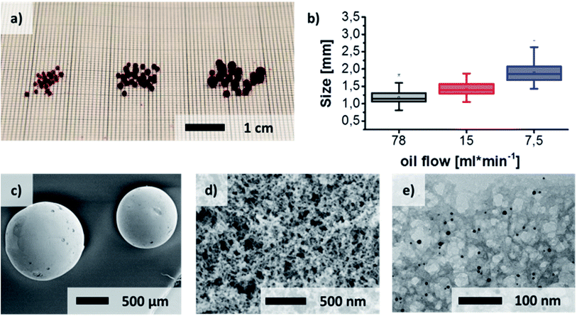
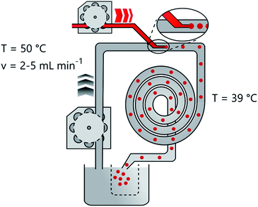
The flow reactor (Fig. 3) consists of a heated oil bath which is pumped continuously by a peristaltic pump through the heat isolated tubing. A T-joint connects the oil flow with the injection needle of the precursor solution which points parallel to the oil flow (Fig. S3†). The 7 m tubing of the reactor is curled into a coil and heat insulated to avoid heat losses and to save space. The hardened gel spheres leave the reactor after 10 min into another beaker which separates them while the excess oil joins the reservoir to keep a constant temperature. Hydrogel spheres with different average diameters of 1.18 ± 0.22 mm, 1.43 ± 0.18 mm and 1.90 ± 0.28 mm respectively can be produced (Fig. 1, Fig. S5†). The pump speed of the oil represents the essential factor for the production of spheres of different sizes. The targeted adjustment of the pump speed thus allows size control (Fig. 1(a) and (b)). Linearity of the pump speed has been investigated for the oil and precursor pump beforehand (Fig. S2†). The injection of the reaction solution into the oil flow leads to the formation of small droplets at the tip of the injection canula. Then, the velocity of the oil flow determines how long the droplets stay on the tip before they are swept away. Furthermore, the velocity of the precursor injection has no influence on the size of the spheres, but on the frequency of the droplet formation. In order to avoid the merging of two consecutive droplets and thus a broader size distribution, the speed was adjusted accordingly. However, merging of two non gelated droplets could not be avoided completely due to the pulsation of the oil pump.Due to the solubility of propylene oxide in paraffin oil, gelation times and reactant volumina have been investigated before testing in the reactor without and with a covering of oil (Fig. S1†). In the presence of oil during the gelation, significantly longer gelation times are observed. This is attributed to a loss of the initial amount of epoxide in the aqueous reaction solution due to diffusion into the oil phase. Testing of the miscibility of the epoxide with silicon oil and paraffin oil yielded a lower miscibility of the latter. Because of these mixing issues the ratio of propylene oxide and aluminium salt was adjusted to yield reasonable gelation times. The gelation times for the aqueous reaction mixture takes 3 hours to gelate at 0 °C and only 5 min at 40 °C in contact with oil. In this way the reaction solution can be stored in an ice bath and then be injected into the to 39 °C heated reactor, where gelation occurs more rapidly. Remaining epoxide residues in the oil can easily be removed by heating up the oil bath. To guarantee a flowing of the spheres in the center of the tubing the reaction solution density was adjusted to 0.87 g cm−3, which corresponds to the surrounding oil at 0.867–0.882 g cm−3 (specification of the producer).
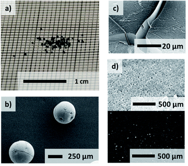
After the solvent exchange and supercritical CO2 drying the aerogel spheres were obtained. Due to the localized surface plasmon resonance (LSPR) of the gold nanoparticles these transparent monolithic aerogel spheres (Fig. S4†) exhibit a red color. A sponge-like network structure of the aerogel spheres is shown in scanning electron microscope images (Fig. 1(d) and (e)). An even distribution of the gold nanoparticles inside the oxide gel matrix can further be observed by transmission electron microscope imaging (Fig. 1(e)). The same structural properties can be determined for the xerogels (Fig. 2).
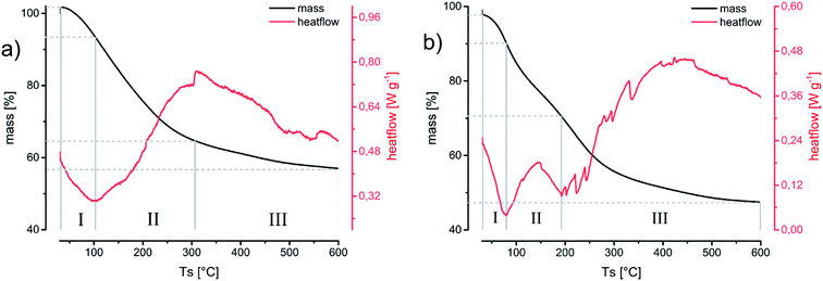
XRD reflections (Fig. 5) show a predominantly amorphous material by a declining intensity towards larger angles. The appearing reflections can be attributed to the gold nanoparticles embedded or inside the oxide aerogel matrix. The small size of the gold particles leads to broadened reflections in respect to their nano crystalline structure. Temperature treatment of the aerogels up to 300 °C still retains the amorphous structure of the material.32 This temperature has been chosen to simulate long temperature exposure during catalysis. DSC/TG-analysis (Fig. 4) from room temperature up to 600 °C yields the endothermic desorption of water until 110 °C and exothermic oxidation processes until 400 °C. This results from oil or solvent residues which remained on the gels’ surface. This process is accompanied by a significant weight loss of 44% in the aerogel and up to 53% in the xerogel, which for the latter can be explained by the higher retention of solvent residue in the gel network due to the drying method.
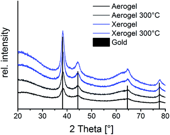 | ||
| Fig. 5 Powder XRD diffractogram of Au/Al2O3 aerogels and xerogels each untreated and heated to 300 °C, reflections can be assigned to gold with an underlying amorphous signal of the aluminium oxide. | ||
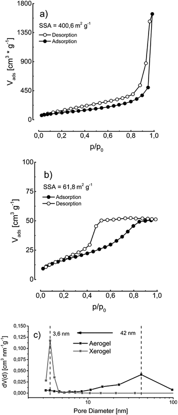
A specific surface area of the aerogel and xerogel of 400 m2 g−1 and respectively 62 m2 g−1 is determined by nitrogen physisorption experiments (Fig. 6). The drying process of the xerogels at standard conditions leads to a partial collapse of the gel network resulting in a smaller specific surface area and a shift of the main pore diameter of 42 nm to 3.6 nm (Fig. 6).
Experimental section
Setting up the droplet reactor
First, a new glass capillary is produced by cleanly breaking of the front part of a glass pipet. This thin glass tube is then built in the T-joint for the injection of the aerogel precursor. Subsequently, one hour before the experiment the oil is heated up to 47 °C in a heating bath (IKA C-MAG HS7 with temperature sensor IKA ETS DS) and pumped continuously through the reactor by a peristaltic pump (Ismatec Ecoline) to heat up the tubes and also remove all remaining air bubbles from the tubing. After exiting the reactor, the oil is recycled into the oil bath, reheated and recycled. Additionally, after every three experiments, the oil is heated to 60 °C in a fume hood for 2 hours to extract the remaining residues of epoxide, which mixed with the oil. The temperature is also monitored externally near the reactor with a temperature sensor to ensure thorough heating of the tubing.Preparation of aerogel precursor
In a general experiment 4.5 ml propylene oxide is added to 6 ml of a solution of 0.5 M AlCl3·6H2O in ethanol. The solution is cooled down to 0 °C to slow down the gelation. Then, 0.6 ml of a gold precursor 0.5 mM solution of HAuCl4 in water is added and reduced by the following addition of 0.6 ml of a 0.5 mM solution of sodium borohydride in water.Injection into the reactor
Into the continuous oil flow of 7.5 ml min−1, 15 ml min−1 and 78 ml min−1 the aerogel precursor solution is injected at a steady speed of 0.36 ml min−1 by a peristaltic pump (Ismatec SA Vario Pump System). The oil used is a paraffin oil from Carl Roth Art. No. 8904.1 (density = 0.867–0.882 g cm−3, viscosity = 220–260 mm2 s−1). Only the oil flow is adjusted to control the particle size. Droplets of the aqueous reaction solution form millimeter sized spheres immediately after injection into the oil. The droplets then travel for around 10 minutes through 7 m tubing with 1 cm inner diameter in the hot oil. During this time the temperature rise in the reaction solution leads to completion of the gelation and the hardened solvogel spheres exit the reactor. The solvogel spheres are caught in a separate beaker, while the oil rejoins the cycle in the reactor.Production of aerogels/xerogels
The solvogel spheres are separated with a sieve from the excess oil and washed immediately 5 times with acetone to remove adhesing oil residue. Over the time span of a week, the spheres are then washed again 5 times with acetone and subsequently 5 times with ethanol to exchange the gel solvent and remove residue from the reaction and the reactants. To create aerogels, the spheres are then dried in an autoclave via high pressure supercritical CO2 drying. To produce xerogels, the gels are left to dry in an open beaker at room temperature.Conclusions
The continuous production of spherical millimeter sized solvogel spheres has been successfully demonstrated using a continuous flow droplet reactor. For this, the interacting parameters of oil flow, gelation time and reactant volumina had to be fitted as well as optimized to the applied setup. The gelation solution is injected into the oil stream as a liquid sol, which then hardens in the hot oil to form solvogels. In a scenario of continuous production, a total volume of 500 ml solvogel, respectively, 13.8 g of the final aerogel are capable to be generated daily. By adjusting the oil flow three different sizes of gels could be produced and successfully dried. The resulting spherical aerogels with diameters of 1.18 ± 0.22 mm, 1.43 ± 0.18 mm and 1.90 ± 0.28 mm exhibit a large specific surface area of 400 m2 g−1 with a uniform distribution of the gold nanoparticles into the oxide aerogel network. Furthermore, they show temperature stability, which in combination with their macroscopic design possibilities makes them suitable candidates for use in packed or fluidized bed reactors in heterogeneous catalysis.Conflicts of interest
There are no conflicts to declare.Acknowledgements
This project was funded by the ERC AdG 2013 AEROCAT. L. T. also would like to thank the DBU for the personal financial support through a PhD scholarship.Notes and references
- J. V. Alemán, A. V. Chadwick, J. He, M. Hess, K. Horie, R. G. Jones, P. Kratochvíl, I. Meisel, I. Mita, G. Moad, S. Penczek and R. F. T. Stepto, Pure Appl. Chem., 2007, 79, 1801–1829 Search PubMed
.
- S. Li, C. A. Wang and L. Hu, J. Am. Ceram. Soc., 2013, 96, 3223–3227 CAS
.
- J. C. H. Wong, H. Kaymak, P. Tingaut, S. Brunner and M. M. Koebel, Microporous Mesoporous Mater., 2015, 217, 150–158 CrossRef CAS
.
- P. Tsou, J. Non-Cryst. Solids, 1995, 186, 415–427 CrossRef CAS
.
- D. R. Rolison and B. Dunn, J. Mater. Chem., 2001, 11, 963–980 RSC
.
- C. Ziegler, S. Klosz, L. Borchardt, M. Oschatz, S. Kaskel, M. Friedrich, R. Kriegel, T. Keilhauer, M. Armbrüster and A. Eychmüller, Adv. Funct. Mater., 2016, 26, 1014–1020 CrossRef CAS
.
- A. C. Pierre and G. M. Pajonk, Chem. Rev., 2002, 102, 4243–4266 CrossRef CAS PubMed
.
- W. Liu, A. K. Herrmann, N. C. Bigall, P. Rodriguez, D. Wen, M. Oezaslan, T. J. Schmidt, N. Gaponik and A. Eychmüller, Acc. Chem. Res., 2015, 48, 154–162 CrossRef CAS PubMed
.
- C. Zhu, D. Wen, M. Oschatz, M. Holzschuh, W. Liu, A. K. Herrmann, F. Simon, S. Kaskel and A. Eychmüller, Small, 2015, 11, 1430–1434 CrossRef CAS PubMed
.
- C. Wang and S. Ro, J. Non-Cryst. Solids, 2006, 352, 35–43 CrossRef CAS
.
- G. Li, Q. Wang, B. Zhao, M. Shen and R. Zhou, J. Hazard. Mater., 2011, 186, 911–920 CrossRef CAS PubMed
.
- P. Kurr, I. Kasatkin, F. Girgsdies, A. Trunschke, R. Schlögl and T. Ressler, Appl. Catal., A, 2008, 348, 153–164 CrossRef CAS
.
- S. Ivanova, V. Pitchon, Y. Zimmermann and C. Petit, Appl. Catal., A, 2006, 298, 57–64 CrossRef CAS
.
- E. M. Fernández and L. C. Balbás, J. Phys. Chem. B, 2006, 110, 10449–10454 CrossRef PubMed
.
- Z. Li, Y. Ji, C. Cadigan and R. M. Richards, Catal. Sci. Technol., 2014, 4, 2520–2525 RSC
.
- A. M. Saeed, C. A. Wisner, S. Donthula, H. Majedi Far, C. Sotiriou-Leventis and N. Leventis, Chem. Mater., 2016, 28, 4867–4877 CrossRef CAS
.
- N. Leventis, C. Sotiriou-Leventis and M. A. Saeed, Patent No. US 9260581 B2, 2016
.
- T. Osaki, K. Yamada, K. Watari, K. Tajiri, S. Shima, T. Miki and Y. Tai, Catal. Lett., 2012, 142, 95–99 CrossRef CAS
.
- E. Iglesia, Appl. Catal., A, 1997, 161, 59–78 CrossRef CAS
.
- F. Zerobin, S. Penthor, O. Bertsch and T. Pröll, Powder Technol., 2017, 316, 569–577 CrossRef CAS
.
- M. Alnaief and I. Smirnova, J. Supercrit. Fluids, 2011, 55, 1118–1123 CrossRef CAS
.
- X. Li, G. Qin, Y. Wang and W. Wei, J. Porous Mater., 2014, 21, 611–621 CrossRef CAS
.
- Y. Yu, M. Zhu and J. Fang, RSC Adv., 2017, 7, 1540–1545 RSC
.
- Z. Xu, L. Gan, Y. Jia, Z. Hao, M. Liu and L. Chen, J. Sol–Gel Sci. Technol., 2007, 41, 203–207 CrossRef CAS
.
- D. Chriti, G. Raptopoulos, M. Papastergiou and P. Paraskevopoulou, Gels, 2018, 4, 66 CrossRef PubMed
.
- X. Leng, W. Zhang, C. Wang, L. Cui and C. J. Yang, Lab Chip, 2010, 10, 2841 RSC
.
- C. Gao, X. Qi, Z. Zhang, S. Chen, B. Li and W. Huang, Int. J. Hydrogen Energy, 2011, 36, 9758–9766 CrossRef CAS
.
- P. Wang, J. Li, J. Nunes, S. Hao, B. Liu and H. Chen, J. Am. Ceram. Soc., 2016, 100, 41–48 CrossRef
.
- A. E. Gash, T. M. Tillotson, J. H. Satcher Jr, L. W. Hrubesh and R. L. Simpson, J. Non-Cryst. Solids, 2001, 285, 22–28 CrossRef CAS
.
- N. Leventis, N. Chandrasekaran, A. G. Sadekar, S. Mulik and C. Sotiriou-Leventis, J. Mater. Chem., 2010, 20, 7456 RSC
.
- N. Leventis, P. Vassilaras, E. F. Fabrizio and A. Dass, J. Mater. Chem., 2007, 17, 1502–1508 RSC
.
- T. F. Baumann, A. E. Gash, S. C. Chinn, A. M. Sawvel, R. S. Maxwell and J. H. Satcher, Chem. Mater., 2005, 17, 395–401 CrossRef CAS
.
Footnote |
| † Electronic supplementary information (ESI) available. See DOI: 10.1039/c9ra09631k |
| This journal is © The Royal Society of Chemistry 2020 |

