 Open Access Article
Creative Commons Attribution 3.0 Unported Licence
Hydrophilic polymer-stabilized porous composite membrane for water evaporation and solar desalination†
Xiaoning Hanab,
Linlin Zangc,
Shaochun Zhangb,
Tianwei Doua,
Liang Lib,
Jian Yangd,
Liguo Sun *b,
Yanhong Zhangb and
Cheng Wang
 *a
*a
aKey Laboratory of Functional Inorganic Material Chemistry (MOE), Heilongjiang University, Harbin, 150080, China. E-mail: wangc_93@163.com
bSchool of Chemical Engineering and Materials, Heilongjiang University, Harbin, 150080, China. E-mail: sunliguo1975@163.com; zhangyanhong1996@163.com
cState Key Laboratory of Urban Water Resource and Environment, Harbin Institute of Technology, Harbin, 150080, China
dHarbin Academy of Products Quality Inspection Supervision, Harbin, 150080, China
First published on 14th January 2020
Abstract
Solar steam generation is considered an effective and sustainable method for addressing freshwater shortages. However, several challenges to developing photothermal materials and improving evaporation performance currently exist. Herein, we designed a hydrophilic evaporator with double-layer structure by combining a hydrophilic polymer with three-dimensional porous carbon nanotube beads on a glass microfiber membrane. Poly(methacrylic acid) acted as a binder to stabilize the carbon-based photothermal layer along with continuously pumped water. The assembled carbon nanotube beads with porous structures not only harvested and converted light to heat but also provided available channels for fast vapor diffusion. An artificial tree evaporation configuration can effectively localize heat on the photothermal layer, which endowed the evaporator with a high evaporation rate of 1.62 kg m−2 h−1 with a solar-to-vapor energy conversion efficiency of 87% under 1 sun illumination. Meanwhile, excellent desalination performance and stable recycling test made the evaporator have great potential in practical applications.
Introduction
Water scarcity has become a severe problem around the world in the past decades because of population growth, industrial development and environmental pollution.1–3 Therefore, membrane separation processes based on reverse osmosis (RO) have been developed to produce clean water from seawater.4 However, sophisticated equipment, complicated pretreatment procedures, high energy consumption, and serious membrane fouling limit its application in remote inland areas and coastal cities.5 Recently, solar-driven interfacial steam generation (SISG) has attracted extensive attention as a promising and sustainable water treatment and desalination technology.6–12 Unlike traditional solar evaporation technologies, photothermal materials in the SISG system can efficiently harvest light and convert it to heat confined water at the interface instead of directly heating bulk water. This reduces heat loss and improves light-to-vapor conversion efficiency.13–17At present, carbon-based photothermal materials are commonly used because of the advantages of their broadband light absorption, low cost, and large-scale preparation.18–20 Carbon nanotubes (CNTs), which have stable physical and chemical properties, good thermal stability and low specific heat capacity, have been particularly used as two-dimensional (2D) light absorbers in solar steam generation. For example, Hu's group prepared a wood-based evaporator by directly coating 2D CNTs on the surface, but this evaporator only achieved a high efficiency of 81% under 10 suns illumination.21 Weng et al. added beeswax into a mixture of CNTs and polydimethylsiloxane to construct an evaporator with a biomimetic superhydrophobic surface.22 Although this method can be widely applied to various substrates, the evaporation rate is less than 1.4 kg m−2 h−1 under 1 sun illumination and the solar-to-vapor conversion efficiency is only 82%. There may be two reasons for this ideal evaporation performance: (1) small pores formed by entangled and stacked 2D CNTs affected water vapor diffusion, or (2) insufficient contact between water and photothermal materials resulted in a low evaporation rate. It has been reported that optimizing the pore structure of carbon-based photothermal materials can effectively maximize light absorption and provide more channels for fast escape of water vapor.23 Therefore, a hierarchically porous structure and good water transportation are critical for improving the evaporation performance of CNTs-based evaporators.
Herein, we prepared a highly efficient solar evaporator consisting of a CNTs-based photothermal layer and a hydrophilic microfiber membrane. Three-dimensional (3D) porous carbon nanotube beads (PCNTBs) with uniform size can be tightly bound via a poly(methacrylic acid) (PMAA) coating and assembled on the surface of the support, thereby forming a stable PCNTBs/PMAA/glass microfiber (PCPG) composite membrane. The porous beads were fabricated by a microfluidic device using polystyrene microspheres as hard template. The abundant pores can confine the light in the beads, while providing channels for water transport and vapor diffusion. Meanwhile, hydrophilic PMAA can promote the efficient transport of water in the composite membrane. Besides, an artificial tree configuration was employed during the evaporation, which can efficiently improve the utilization and localization of the converted heat energy according to Mi and her co-authors' report.5 These features can enhance the evaporation performance of the PCPG composite membrane, making it a promising photothermal evaporator for solar desalination and water treatment.
Experiment
Materials
CNTs (diameter = 20–40 nm, length = 1–2 μm) were purchased from Shenzhen Nanotech Port Co., Ltd. Concentrated sulfuric acid, concentrated nitric acid, methyl acrylic acid (MAA), potassium persulfate and styrene monomer were purchased from Sinopharm Chemical Reagent Co., Ltd. Dimethyl silicone and n-hexane were purchased from Tianjin Fuyu Chemical Reagent Co., Ltd. The glass microfiber membrane was purchased from Whatman, UK and the average pore size was 1.2 μm. Poly(methyl acrylic acid) (PMAA, Mw = 310![[thin space (1/6-em)]](https://www.rsc.org/images/entities/char_2009.gif) 000) was fabricated by free radical polymerization.24,25
000) was fabricated by free radical polymerization.24,25
Preparation of the PCPG composite membrane
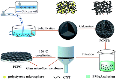
Fig. 1 shows the preparation process for the PCPG composite membrane. First, the PCNTBs were fabricated via the hard template method using a modified microfluidic device.26–28 The detailed synthesis process of the PCNTBs was described in the ESI.† Next, 12 mg of the as-prepared PCNTBs was uniformly dispersed into 6 mL of a 4 wt% synthesized PMAA solution. The mixture was poured into a filter and the beads were deposited on a 2 cm-diameter glass microfiber membrane. After being dried at 70 °C for 20 min, the composite membrane was cross-linked in an oven at 120 °C for 1 h. The loading mass of PMAA and PCNTBs was 27 mg. For comparison, carbon nanotube beads (CNTBs) were prepared by the same steps as the PCNTBs, except using polystyrene microspheres. And the CNTBs/PMAA/glass microfiber (CPG) composite membrane was prepared by the same method as the PCPG.Solar steam generation experiments
In this work, we constructed an artificial tree evaporation configuration to perform the solar steam generation. Deionized (DI) water, saline water or seawater was put into a quartz container with a diameter of 2.1 cm and the container was wrapped by thermal insulation material. The circular sample (2 cm in diameter) was placed on a polystyrene foam with low thermal conductivity during evaporation. The simulated solar was used to illuminate the composite membrane vertically from the top, and the water mass loss was continuously recorded for 60 min. During the experiment, the surrounding temperature and humidity maintained at 23 °C and 13%, respectively. The surface temperature of the composite membrane was measured using an IR camera.Characterization
The morphology and structure were explored by using scanning electron microscope (SEM, S-4800). FTIR spectra were obtained with ADVANCE III, and all samples were prepared by potassium bromide pellet method. X-ray diffraction (XRD) patterns were tested by a Bruker D8 Advance with a Cu Kα radiation. The simulated sunlight source was a 300 W xenon lamp (Microsolar 300UV, Perfect light). The light intensity was calibrated by a photo radiometer (PL-MW2000, Perfect light). Meanwhile, the temperature was measured by an infrared radiation (IR) camera (FLIR One Pro). The absorption spectrum was recorded using an UV-vis-NIR spectrometer (Shimadazu, UV 2550). Contact angle measurement was performed using a contact angle meter (OCA20, Dataphysics).Results and discussion
Characterizations of the PCNTBs
The CNTs after acid treatment still maintained the winding structure (Fig. S1†). The acidified CNTs with oxygen-containing groups indicated that they can uniformly disperse in composite droplets produced by the microfluidic device (Fig. S2†). Furthermore, in the solidification process, the acidified CNTs wrapped around the embedded hydrophilic polystyrene microspheres (360 ± 5 nm), resulting in a dense structure when water evaporating (Fig. S3†). It can be seen from Fig. S3c and d,† a large number of polystyrene microspheres randomly stacked. And the characteristic peaks of polystyrene microspheres and acidified CNTs are obviously observed in acidified CNTs/polystyrene beads (Fig. S4†). After high temperature calcination, polystyrene microspheres were removed from the composite beads as the hard template to form the porous structure throughout the beads (Fig. 2a–f). As shown in Fig. 2a, the acidified CNTs were made into 3D self-supporting beads with an average diameter of 200 ± 20 μm. Among them, assembled polystyrene microspheres resulted in the formation of submicron pores between the entangled CNTs (Fig. 2c and f), while larger pores were generated due to a large number of randomly stacked microspheres (Fig. 2b and e). The three-dimensionally structured PCNTBs possessed interconnected porous structure, therefore light can be multi-scattered in pores to promote light absorption.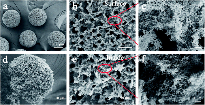 | ||
| Fig. 2 SEM images of (a) the PCNTBs, (b) and (c) the surface structure of the PCNTBs, (d) the broken PCNTBs, (e) and (f) the inside structure of the PCNTBs. | ||
Furthermore, in order to investigate the robustness of the PCNTBs, the beads were added to different shear flows to observe the spherical changes (Fig. S5†). It can be seen from the microscopy images that the PCNTBs both maintained good spherical morphologies after stirring in water for 15 min at different stirring speeds. The results demonstrate that the PCNTBs have good mechanical robustness, which is beneficial to the preparation of the composite membrane and the water evaporation experiment.
Characteristics of the PCPG composite membrane
The PCPG composite membrane was cut by a scissor for SEM characterization. The CNTs-based photothermal layer was deposited on the surface of the support to form the PCPG composite membrane following the filtration treatment (Fig. 3a). As shown in Fig. 3b and c, the interconnected porous structure of the surface and inside of the PCNTBs on the PCPG composite membrane was still maintained after filtration. The large pores in the porous beads provide conditions for the formation of water channels. Meanwhile, the interconnected porous structure is beneficial for providing channels for fast vapor diffusion. | ||
| Fig. 3 SEM images of (a) the cross-section view, (b) the surface structure and (c) the inside structure of the PCPG composite membrane. | ||
The water transport capacity of the solar evaporator is critical for solar steam generation experiments. The water contact angle of the PCPG and the PCNTBs were tested, it was found that the PCPG composite membrane with PMAA exhibited excellent hydrophilicity (Fig. S6†). Fig. 4a–d show that the PCPG composite membrane was completely wetted in 90 seconds, demonstrating the excellent hydrophilicity and water transportation of the PCPG composite membrane. FTIR spectra indicate that the PCPG exhibits a strong peak at approximately 1730 cm−1, this is assigned to the carboxyl group of PMAA, which is absent in PCNTBs (Fig. 4e). XRD patterns show the PCPG retains the diffraction peaks of the CNTs and PMAA, centered at 26.1° and 15°, respectively (Fig. 4f). The above results proved PMAA was successfully mixed as the binder between the beads after the filtration.
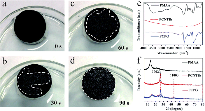 | ||
| Fig. 4 (a–d) Photographs of dynamic water absorption of the PCPG composite membrane; (e) FTIR spectra and (f) XRD patterns of PMAA, the PCNTBs and the PCPG. | ||
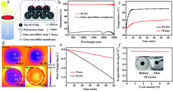
Fig. 5a shows a diagram of the solar evaporator, which was made of the PCPG composite membrane, polystyrene foam, a 2D glass microfiber strip and a glass container. In the artificial tree-like system, the glass microfiber acted as a trunk to transfer water from the bulk water to the composite membrane by capillary action. The composite membrane as leaves can localize heat to vaporize surrounding water bound by PMAA from the hydrophilic support, while the porous structure provides many channels for fast vapor diffusion. The light absorption spectra were used to determine the light absorption ability of the PCPG composite membrane. As shown in Fig. 5b, the light absorbance of the composite membrane can reach 98% in the wavelength range of 250–2500 nm, which much higher than that of the glass microfiber membrane. In contrast, the light absorption of the CPG (94%) showed a decreased intensity (Fig. S7†). These results indicate that the good light absorption of the PCPG could be attributed to the intrinsic absorption properties of CNTs and multiple scattering of light in the porous structure.29 The high light absorption made the surface temperature of the PCPG composite membrane rise to 44.2 °C in 10 minutes, while the surface temperature of water below 26 °C (Fig. 5c). After 1 h of illumination, the surface temperature of the composite membrane was 45.2 °C which was 14.7 °C higher than that of only water (Fig. 5d). Meanwhile, the temperature of the bulk water in the tree-like evaporation configuration was kept at 28 °C due to the presence of the thermal insulation. Therefore, it can be seen that the artificial tree configuration can effectively localize the converted heat on the photothermal layer, thereby realizing the interfacial water evaporation. In contrast, the direct evaporation of water remarkably led to energy waste. The PCPG composite membrane had a higher evaporation rate when the content of PCNTBs was 12.0 mg (Fig. S8†), which was 1.62 kg m−2 h−1 and about 3.4 times larger than that of pure water (Fig. 5e). In comparison, the evaporation rate of the CPG dropped to 1.43 kg m−2 h−1 (Fig. S9†). Moreover, solar-to-vapor conversion efficiency (η) was calculated according to the following equation:5
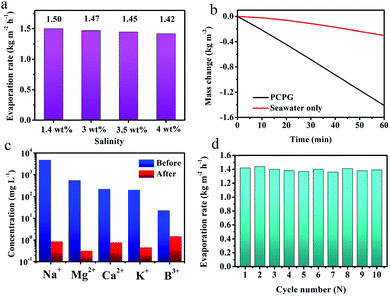
Besides, we investigated the solar desalination performance in the simulated saline water and actual seawater using the tree-like evaporator. As we known, the vapor pressure of saline water is lower than the pure water due to the presence of various salt ions. At the same time, the viscosity of the solution becomes large as the salt concentration increases concentration increases. Therefore, the evaporation rate in the saline water is a lower than that in the pure water without ion interference. During the vaporization of saline water with different NaCl concentrations, the evaporation rate did not significantly change, which was maintained at around 1.45 kg m−2 h−1 (Fig. 6a). These results indicate that the PCPG composite membrane still maintains the freshwater production capacity even in saline water. For actual seawater (seawater sample average salinity ≈ 3.5 wt%, from Bohai Sea, China), the evaporation rate using the tree-like configuration was as high as 1.41 kg m−2 h−1, which was 4.6 times faster than that direct evaporation of seawater (Fig. 6b). And concentrations of Na+, Mg2+, K+, B3+ and Ca2+ in the product water were much lower than the initial concentration in seawater, which meet WHO's water quality requirements for drinking water quality (Fig. 6c). These results demonstrate that the PCPG composite membrane has prominent desalination performance. Moreover, recycling stability of the PCPG composite membrane was proved by a multiple cycle evaporation test in the actual seawater. As shown in Fig. 6d, the evaporator had a stable evaporation rate of approximately 1.4 kg m−2 h−1 during 10 cycles of recycling.
Conclusions
We successfully prepared a hydrophilic evaporator with a PMAA/PCNTBs photothermal layer. Under 1 sun illumination, it exhibits a high evaporation rate of 1.62 kg m−2 h−1 and a solar-to-vapor conversion efficiency of 87%. The unique 3D porous structure of the PCPG composite membrane enables it to have a high light absorption and vapor escape channels. Meanwhile, the porous structure and hydrophilic PMAA can promote the transport of water, thereby improving the water evaporation efficiency. Furthermore, the excellent desalination performance and stable reusability make it a promising evaporator for solar desalination and water treatment.Conflicts of interest
There are no conflicts to declare.Acknowledgements
The present study has been supported by NSFC (51973051 and 51527804) and Heilongjiang Natural Science Foundation Project (LH2019E077).Notes and references
- M. M. Mekonnen and A. Y. Hoekstra, Sci. Adv., 2016, 2, e1500323 CrossRef PubMed.
- Q. Schiermeier, Nature, 2014, 505, 10–11 CrossRef PubMed.
- I. Haddeland, J. Heinke, H. Biemans, S. Eisner, M. Florke, N. Hanasaki, M. Konzmann, F. Ludwig, Y. Masaki, J. Schewe, T. Stacke, Z. D. Tessler, Y. Wada and D. Wisser, Proc. Natl. Acad. Sci. U. S. A., 2014, 111, 3251–3256 CrossRef CAS PubMed.
- M. Elimelech and W. A. Phillip, Science, 2011, 333, 712–717 CrossRef CAS PubMed.
- C. Finnerty, L. Zhang, D. L. Sedlak, K. L. Nelson and B. X. Mi, Environ. Sci. Technol., 2017, 51, 11701–11709 CrossRef CAS PubMed.
- X. Y. Zhou, F. Zhao, Y. H. Guo, Y. Zhang and G. H. Yu, Energy Environ. Sci., 2018, 11, 1985–1992 RSC.
- H. Ghasemi, G. Ni, A. M. Marconnet, J. Loomis, S. Yerci, N. Miljkovic and G. Chen, Nat. Commun., 2014, 5, 4449 CrossRef CAS PubMed.
- P. Tao, G. Ni, C. Y. Song, W. Shang, J. B. Wu, J. Zhu, G. Chen and T. Deng, Nat. Energy, 2018, 3, 1031–1041 CrossRef.
- X. Y. Zhou, Y. H. Guo, F. Zhao and G. H. Yu, Acc. Chem. Res., 2019, 52, 3244–3253 CrossRef CAS PubMed.
- F. Zhao, X. Y. Zhou, Y. Shi, X. Qian, M. Alexander, X. P. Zhao, S. Mendez, R. G. Yang, L. T. Qu and G. H. Yu, Nat. Nanotechnol., 2018, 13, 489–495 CrossRef CAS PubMed.
- X. Y. Zhou, F. Zhao, Y. H. Guo, B. Rosenberger and G. H. Yu, Sci. Adv., 2019, 5, eaaw5484 CrossRef PubMed.
- Y. H. Guo, X. Y. Zhou, F. Zhao, J. W. Bae, B. Rosenberger and G. H. Yu, ACS Nano, 2019, 13, 7913–7919 CrossRef CAS PubMed.
- X. Y. Huang, Y.-H. Yu, O. L. de Llergo, S. M. Marquez and Z. D. Cheng, RSC Adv., 2017, 7, 9495–9499 RSC.
- R. Chen, Z. J. Wu, T. Q. Zhang, T. C. Yu and M. M. Ye, RSC Adv., 2017, 7, 19849–19855 RSC.
- R. Chen, K. H. Zhu, Q. M. Gan, Y. Q. Yu, T. Q. Zhang, X. W. Liu, M. M. Ye and Y. D. Yin, Mater. Chem. Front., 2017, 1, 2620–2626 RSC.
- M. M. Ye, J. Jia, Z. J. Wu, C. X. Qian, R. Chen, P. G. O'Brien, W. Sun, Y. C. Dong and G. A. Ozin, Adv. Energy Mater., 2017, 7, 1601811 CrossRef.
- F. H. Liu, L. J. Wang, R. Bradley, B. Y. Zhao and W. P. Wu, RSC Adv., 2019, 9, 29414–29423 RSC.
- Y. C. Wang, L. B. Zhang and P. Wang, ACS Sustainable Chem. Eng., 2016, 4, 1223–1230 CrossRef CAS.
- L. Shi, Y. C. Wang, L. B. Zhang and P. Wang, J. Mater. Chem. A, 2017, 5, 16212–16219 RSC.
- P. Wang, Environ. Sci.: Nano, 2018, 5, 1078–1089 RSC.
- C. J. Chen, Y. J. Li, J. W. Song, Z. Yang, Y. D. Kuang, E. Hitz, C. Jia, A. Gong, F. Jiang, J. Y. Zhu, B. Yang, J. Xie and L. B. Hu, Adv. Mater., 2017, 29, 1701756 CrossRef PubMed.
- D. H. Weng, F. C. Xu, X. Li, Y. Li and J. Q. Sun, J. Mater. Chem. A, 2018, 6, 24441–24451 RSC.
- M. M. Gao, L. L. Zhu, C. K. Peh and G. W. Ho, Energy Environ. Sci., 2019, 12, 841–864 RSC.
- L. L. Zang, J. Ma, D. W. Lv, Q. L. Liu, W. L. Jiao and P. P. Wang, J. Mater. Chem. A, 2017, 5, 19398–19405 RSC.
- L. L. Zang, R. Lin, T. W. Dou, L. Wang, J. Ma and L. G. Sun, Nanoscale Adv., 2019, 1, 389–394 RSC.
- L. R. Shang, F. Q. Shangguan, Y. Cheng, J. Lu, Z. Y. Xie, Y. J. Zhao and Z. Z. Gu, Nanoscale, 2013, 5, 9553–9557 RSC.
- L. R. Shang, Y. Cheng, J. Wang, H. B. Ding, F. Rong, Y. J. Zhao and Z. Z. Gu, Lab Chip, 2014, 14, 3489–3493 RSC.
- Y. Cheng, F. Y. Zheng, J. Lu, L. R. Shang, Z. Y. Xie, Y. J. Zhao, Y. P. Chen and Z. Z. Gu, Adv. Mater., 2014, 26, 5184–5190 CrossRef CAS PubMed.
- Y. Yang, R. Q. Zhao, T. F. Zhang, K. Zhao, P. S. Xiao, Y. Ma, P. M. Ajayan, G. Q. Shi and Y. S. Chen, ACS Nano, 2018, 12, 829–835 CrossRef CAS PubMed.
Footnote |
| † Electronic supplementary information (ESI) available. See DOI: 10.1039/c9ra09667a |
| This journal is © The Royal Society of Chemistry 2020 |

