 Open Access Article
Enhanced dispersibility of metal–organic frameworks (MOFs) in the organic phase via surface modification for TFN nanofiltration membrane preparation†
Hengrao Liua,
Min Zhanga,
Hao Zhaoa,
Yanjun Jiang a,
Guanhua Liu
 *ab and
Jing Gao*a
aSchool of Chemical Engineering and Technology, Hebei University of Technology, Tianjin 300130, China. E-mail: ghliu@hebut.edu.cn; jgao@hebut.edu.cn
bTianjin Key Laboratory of Chemical Process Safety, Hebei University of Technology, Tianjin 300130, China
First published on 23rd January 2020
Abstract
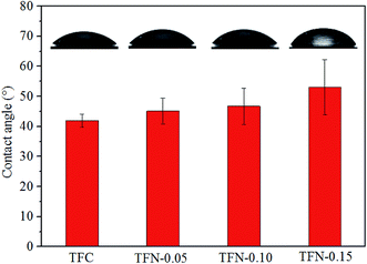
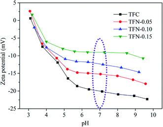
The nanosized UiO-66-NH2 metal–organic framework (MOF) material was synthesized and modified by palmitoyl chloride to enhance the dispersibility and restrain the aggregation of MOF particles in the organic phase. Then the above nanomaterial was introduced into interfacial polymerization to prepare thin film nanocomposite (TFN) nanofiltration membranes. The prepared membranes displayed “ridge-valley” shaped Turing structure surface morphology with membrane thickness around 380 nm. The FE-SEM, ATR-FTIR and XPS characterization showed the polyamide layer was fabricated on the substrate surface. The TFN membranes showed higher hydrophobicity, zeta potential and roughness than TFC membranes. Due to the introduction of MOF and the formation of MOF/polyamide interfacial passageways, the TFN membranes showed higher water permeability but slightly lower rejection properties than TFC membranes. Compared with the TFN membranes prepared from pristine UiO-66 and UiO-66-NH2, the TFN membrane prepared from modified UiO-66-NH2 showed better rejection properties because of its superior dispersibility in the organic phase.
1 Introduction
Separation is one of the most crucial processes in the chemical industry. Conventional separation technologies, such as distillation, adsorption, and extraction, consume vast amounts of energy or chemical materials. So developing an energy-saving and economical separation technology is of great significance in the chemical industry. Membrane separation is a promising candidate that has emerged in recent decades by reason of no phase transition, energy-efficiency, simple equipment requirement and easy operation process.1–3Nanofiltration is a kind of membrane separation technology, possessing a membrane pore size about 1 nm.4 Polyamide (PA) thin film composite (TFC) membrane was wildly used in nanofiltration and reverse osmosis such as desalination, dye separation and waste water treatment, but the “trade-off” effect between permeability and selectivity is a common problem in TFC membrane.5 Researchers have made great effort to improve the permeability of TFC membrane without losing solute selectivity. Hoek and his coworkers brought forward the idea of fabricating thin film nanocomposite (TFN) membranes by incorporating zeolite nanoparticles within the polyamide matrix.6 In their research, the TFN membranes showed increased permeability with the increase of filler loading and still maintained high rejection property. From then on, many kinds of inorganic nanomaterials (such as SiO2, TiO2, graphene oxide and carbon nanotube) were introduced into interfacial polymerization process to prepare TFN membranes.7 The incorporated nanomaterials could create additional passageways for solvent transfer through their interconnected nanopores or nanomaterial–polyamide interfaces.
Metal–organic frameworks (MOFs) are a series of porous organic–inorganic hybrid materials, which consist of inorganic metal nodes linked with organic ligands by coordination bonds.8 The intrinsic nanopores of MOFs can be employed as the solvent transfer passageways in nanofiltration process.9 Furthermore, the size of particle/pore, and the property of surface/pore are highly tunable to meet the demand of membrane preparation.10 In addition, the presence of organic ligands results in better compatibility with polymer matrix. So MOFs are regarded as ideal materials to prepare TFN membranes. In traditional ways, if MOFs are dispersed in aqueous phase in interfacial polymerization process to prepare TFN membrane, a large amount of MOFs will be removed together with the excess amine solution, leaving only very little MOFs loaded on the substrate surface, which restricts the effect of the MOFs.11 While one of the greatest challenge to disperse MOF nanoparticles in organic phase is the particle aggregation,12 which is ascribed to the poor dispersibility of nanomaterials in membrane casting solution especially in organic phase. The aggregation tendency of inorganic nanoparticles in solution was an intrinsic challenge because of the high surface energy, large specific surface area and strong interaction between nanoparticles. Under these factors, nanoparticles are easy to aggregate together to reduce the total surface energy of particles which eventually reaches an equilibrium state. The serious aggregation of nanoparticles may bring defects into TFN membrane's selective layer, which can lead to significant decrease of rejection property. To restrain the aggregation of MOF nanoparticles, Li et al. prepared high-performance MOF based nanofiltration membranes by coordination-driven in situ self-assembly method,13,14 the prepared membranes showed outstanding nanofiltration performance. Zhu et al. modified ZIF-8 MOF particles with poly(sodium 4-styrenesulfonate) and introduced it into interfacial polymerization.15 The prepared TFN nanofiltration membrane showed obvious increase in water permeability and achieved analogous rejection property at low ZIF-8 loading amount. Guo et al. synthesized UiO-66-NH2 and modified the surface by dodecyl aldehyde to prepare TFN membranes for organic solvent nanofiltration.16 The TFN membrane exhibited both high methanol permeance and high rejection to tetracycline. From the above instances, surface modification is a promising method to improve dispersibility and reduce aggregation of nanoparticles in the preparation process of TFN membranes.
Among various MOFs, zirconium MOFs aroused great concern of researchers due to the high stability, diverse organic ligands with changeable function groups (for example –NH2, –OH, –COOH and so on),17,18 and ease of modification to change the surface property. UiO-66-NH2 was a kind of Zr-based MOFs, which was made up of Zr ions linked by 2-aminobenzene-1,4-dicarboxylic acid organic ligands. The highly reactive –NH2 groups situated in the internal pores and outside surface of UiO-66-NH2, which made it possible to be easily modified by various chemical reagents to change its surface property and increase the dispersity in casting solution.
For this reason, UiO-66-NH2 nanomaterial was synthesized and the outside surface was modified by palmitoyl chloride in a facile way, then the modified UiO-66-NH2 nanomaterial was dispersed in TMC/cyclohexane organic phase and introduced into interfacial polymerization process to fabricate TFN membranes. On the one hand, the long alkyl chain of palmitoyl chloride on the outside surface can increase the compatibility between UiO-66-NH2 nanoparticles and nonpolar organic solvent because of their similar polarity, and hence decrease the aggregation tendency between nanoparticles. On the other hand, compared with n-hexane used in most researches, the use of cyclohexane as organic solvent in this study can lead to better dispersity of nanometerial in organic phase. For the above-mentioned reasons, the modified UiO-66-NH2 nanoparticles can get good dispersibility in organic phase to form stable suspension of nanoparticles during interfacial polymerization to inhabit the formation of nonselective defects in TFN membranes. The morphology, ATR-FTIR, XPS, hydrophilicity, zeta potential, and surface roughness of the prepared membranes were characterized. The influence of the modified UiO-66-NH2-PC concentration in organic phase on membrane property and the long-term stability of the membrane was investigated in detail.
2 Experimental section
2.1 Materials and reagents
Commercial polyacrylonitrile (PAN) ultrafiltration membrane (MWCO: 50![[thin space (1/6-em)]](https://www.rsc.org/images/entities/char_2009.gif) 000) was bought from Beijing Separate Equipment Co. Ltd. NaOH, Na2SO4, MgSO4, NaCl, n-hexane, cyclohexane, trichloromethane (CHCl3) triethylamine, and acetic acid glacial were bought from Tianjin Fengchuan Chemical Reagent Technologies Co. Ltd. Zirconium chloride (ZrCl4), piperazine (PIP), N,N-dimethylformamide (DMF), and benzene-1,3,5-tricarbonyl trichloride (TMC) were bought from Aladdin Biochemical Technology Co. Ltd. Palmitoyl chloride was bought from Macklin Biochemical Co. Ltd. 2-Aminoterephthalic acid (NH2-BDC) was bought from Dibai Chemical Technology Co. Ltd.
000) was bought from Beijing Separate Equipment Co. Ltd. NaOH, Na2SO4, MgSO4, NaCl, n-hexane, cyclohexane, trichloromethane (CHCl3) triethylamine, and acetic acid glacial were bought from Tianjin Fengchuan Chemical Reagent Technologies Co. Ltd. Zirconium chloride (ZrCl4), piperazine (PIP), N,N-dimethylformamide (DMF), and benzene-1,3,5-tricarbonyl trichloride (TMC) were bought from Aladdin Biochemical Technology Co. Ltd. Palmitoyl chloride was bought from Macklin Biochemical Co. Ltd. 2-Aminoterephthalic acid (NH2-BDC) was bought from Dibai Chemical Technology Co. Ltd.
2.2 Synthesis and modification of UiO-66-NH2 nanomaterial
Zr-based MOFs UiO-66-NH2 nanomaterial was synthesized as follows: ZrCl4 (0.686 mmol) and NH2-BDC (0.686 mmol) were dissolved in 40 mL DMF. Then 20 μL H2O and 1.2 mL acetic acid glacial were added. Acetic acid glacial could decrease growth rate of Zr-based MOF crystals and hence increase the crystallinity of MOF nanoparticles. The OH− of water molecules could be employed as the composition of secondary building units in UiO-66-NH2 crystal structure. The above mixture was sonicated and stirred to dissolve completely and then heated at 100 °C for 24 h. The resulting product was centrifuged and washed 3 times by DMF and then washed 2 times by ethanol. 1 mL UiO-66-NH2 suspension was dried thoroughly to confirm the weight and concentration of UiO-66-NH2.The above purified UiO-66-NH2 nanoparticles (2 g) were dispersed in the mixture of 40 mL CHCl3 and 2.4 mL palmitoyl chloride. 1.4 mL triethylamine was added afterwards. The resultant mixture was sonicated to disperse and stirred at room temperature overnight to make UiO-66-NH2 react with palmitoyl chloride. The product was washed by CHCl3 3 times and cyclohexane 3 times and then re-dispersed in cyclohexane. The modified UiO-66-NH2 was named as UiO-66-NH2-PC. The modification scheme was displayed in Fig. S1† and the method of calibrating UiO-66-NH2-PC concentration was similar to that of UiO-66-NH2.
2.3 Hydrolyzation of PAN substrate membrane
The commercially available PAN ultrafiltration membrane was used as the substrate to prepare nanofiltration membranes. Prior to the preparation process, the PAN ultrafiltration membrane was put in NaOH solution (1 mol L−1) at 50 °C for 1 h to make –CN hydrolyze to –COOH, and the resultant membrane was denoted as HPAN. The existence of ionized –COOH can adsorb electropositive amine monomer in the following interfacial polymerization process and increase the hydrophilicity of the substrate.2.4 Preparation of TFC and TFN membranes
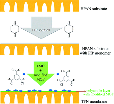
The TFN membranes were prepared by interfacial polymerization. Before the preparation process, the UiO-66-NH2-PC nanoparticles with different concentration (0.05% w/v, 0.10% w/v, and 0.15% w/v) were dispersed into TMC/cyclohexane organic solution (0.15% w/v). The HPAN substrate membrane was immersed in PIP aqueous solution (0.15% w/v) for 20 min. Then the substrate was taken out from PIP solution and removed the excess solution on the substrate surface by dustless bibulous paper. Afterwards, the substrate membrane with PIP solution inside the pores was immersed into the above organic solution for 2 min. The membranes prepared with the UiO-66-NH2-PC concentration of 0.05% w/v, 0.10% w/v, and 0.15% w/v in organic solution were named as TFN-0.05, TFN-0.10 and TFN-0.15, respectively. The concentration of UiO-66-NH2-PC in organic solution could be confirmed by different volume of UiO-66-NH2-PC suspension. The schematic diagram was shown in Fig. 1.The TFC membrane was prepared by the similar method of TFN membranes without adding UiO-66-NH2-PC nanoparticles in organic phase.
2.5 Characterization methods
Field emission scanning electron microscopy (FE-SEM FEI Nova NanoSEM450) was employed to observe the morphologies of UiO-66-NH2 and UiO-66-NH2-PC. The surface and cross-section morphologies of TFC and TFN membranes were also observed by FE-SEM. Fourier transform infrared (FTIR) spectra were obtained through a Bruker Vertex 70 spectrometer to characterize the chemical constitutions of UiO-66-NH2, UiO-66-NH2-PC and the prepared membranes. Water contact angles of TFC and TFN membranes were measured by an optical contact angle measuring system (KRUSS DSA-100). The crystallinities of synthesized UiO-66-NH2 and UiO-66-NH2-PC were confirmed by the X-ray diffractometer (XRD, Bruker AXS D8 Focus). Zeta potential of the prepared membranes was tested by SurPASS electrokinetic analyzer (Anton Paar GmbH), and the roughness was measured by Atomic Force Microscope (AFM, Bruker).2.6 Measurement of nanofiltration performance
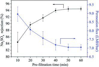
The permeability and rejection properties of the membranes were measured using a dead-end filtration equipment with magnetic stirring function to evaluate the nanofiltration performance. Before measurement, the as-prepared membranes was cut into a rotundity with specific diameter and then the membrane was placed into a filtration cell. The membranes was pre-filtrated at 4 bar for 50 min to reach a stable condition. Then the pure water permeability (PWP) and rejection properties were measured with the duration of 3 min.PWP could be calculated as follows:
Rejection properties were measured by divalent and monovalent salt solution (MgSO4, Na2SO4 and NaCl, 0.1% w/v), the rejection for each salt solution could be determined as follows:
3 Results and discussion
3.1 Characterization of UiO-66-NH2 and UiO-66-NH2-PC
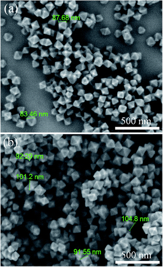
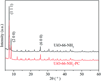
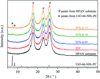
The morphologies of the synthesized UiO-66-NH2 and UiO-66-NH2-PC were shown in Fig. 2. The regular-octahedral appearance could be clearly seen in the figures. The particle size of UiO-66-NH2 was about 80–90 nm. After modification, the particles size enlarged a little to about 100 nm.To further characterize the well-synthesized UiO-66-NH2 nanoparticles, the XRD patterns were applied to analyze the structure of synthesized material. In Fig. 3, the measured diffraction pattern of UiO-66-NH2 was in consistent with the reported literature,12,19 which confirmed the great crystallinity of the synthesized UiO-66-NH2. The sharp characteristic peaks at 2θ = 7.3°, 8.4° and 25.7° were ascribed to (1 1 1), (2 0 0) and (6 0 0) crystal planes, respectively. After modified by palmitoyl chloride, the XRD pattern of UiO-66-NH2-PC remained unchanged, indicating the crystal structure was maintained. The regular-octahedral morphology, nanosized particles and the accurate XRD pattern revealed the successful synthesis of UiO-66-NH2 nanoparticles.
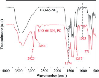
Fig. 4 shows the FT-IR spectra of the synthesized UiO-66-NH2 and UiO-66-NH2-PC. The absorption band at about 3200–3600 cm−1 was ascribed to the stretching vibration of –NH2. The absorption peaks at 1574 and 1257 cm−1 were ascribed to the stretching vibration of C–O and C–N in NH2-BDC, respectively. The absorption peak at 771 cm−1 was ascribed to the Zr–O bonds of metal nodes in the framework.12
The new absorption peaks at 2925 and 2854 cm−1, which were appeared only in UiO-66-NH2-PC, were ascribed to C–H stretching vibration of the modified palmitoyl chloride. And the new absorption peak at 1033 cm−1 was ascribed to C–C stretching vibration of palmitoyl chloride.16 These 3 new absorption peaks indicated that the surface of UiO-66-NH2 was successfully modified by palmitoyl chloride.
The dispersibility of nanoparticles in solvent depends on the interaction within particles, and the interaction between particle and solvent. The surface modification of UiO-66-NH2 by palmitoyl chloride could increase the compatibility between particle and solvent, which enhanced the dispersibility in nonpolar solvent (such as n-hexane and cyclohexane). In order to confirm the above assumption, UiO-66-NH2 and UiO-66-NH2-PC nanoparticles were dispersed in n-hexane and cyclohexane by ultrasonication and then stood for specific time. The unmodified UiO-66-NH2 particles precipitated immediately in few seconds in n-hexane indicating the strong interaction between particles in n-hexane, which was in consistent with the phenomenon of other researchers.16 This phenomenon revealed that it’s impossible to disperse UiO-66-NH2 in n-hexane. Fig. 5 showed the dispersibility of UiO-66-NH2 and UiO-66-NH2-PC in n-hexane and cyclohexane. After still standing for 30 min, the unmodified UiO-66-NH2 particles precipitated completely in cyclohexane, and the UiO-66-NH2-PC particles began to precipitate in n-hexane, but the UiO-66-NH2-PC particles still well suspended in cyclohexane. After still standing for 12 h, only UiO-66-NH2-PC particles could suspend in cyclohexane. The dispersibility experiment indicated that cyclohexane (rather than n-hexane) was better for the nanoparticle dispersion in this study, and surface modification of UiO-66-NH2 by palmitoyl chloride could significantly increase the dispersibility of the synthesized nanoparticles in nonpolar organic solvent. It could be deduced reasonably that the use of cyclohexane as organic solvent and surface modification of nanoparticles could lead to the best dispersion state of UiO-66-NH2 in organic phase during the preparation process of TFN membranes by interfacial polymerization.
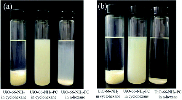 | ||
| Fig. 5 Dispersibility of UiO-66-NH2 and UiO-66-NH2-PC in cyclohexane and n-hexane after standing for (a) 30 min and (b) 12 h. | ||
3.2 Characterization of the prepared membranes
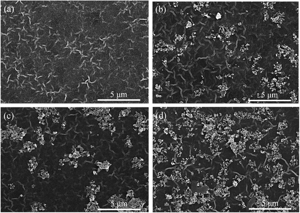 | ||
| Fig. 6 FE-SEM images of surface morphologies of TFC (a), TFN-0.05 (b), TFN-0.10 (c), TFN-0.15 (d) membranes. | ||
The prepared TFC membrane showed typical “ridge-valley” morphology. The white and bright stripe was the convex ridge, and the dark background was the valley region. This striped morphology was a kind of Turing structure, which was different from the spotted morphology in other literature.20–22 The morphology of nanofiltration membranes prepared by interfacial polymerization depended on many factors: the property of the substrate, the diffusion rate of PIP at water/organic interface, and the interaction between amine monomer and the substrate, etc. Generally, the initial interfacial polymerization reaction proceeds at water/organic interface and the PA selective layer grows towards the organic phase side along with the PIP monomers diffusing from water to organic phase because of the disadvantageous partition coefficient of the acid chloride monomers in water. The diffusion rate of the two monomers has a remarkable impact on the morphology of TFC membranes. Under most conditions, the diffusion rate of PIP is less than that of TMC, but the diffusion rate disparity of the two monomers is not very significant (within the same order of magnitude), which leads to spotted morphology in the polyamide membrane. When the diffusion rate disparity of the two monomers comes up to orders of magnitude leading to diffusion-driven instability, the striped Turing structure could appear.23 In this study, the HPAN substrate contained abundant negative charged carboxyl groups that could interact with PIP monomers via electrostatic force and hydrogen bonds, which decreased the diffusion rate of PIP molecules during the interfacial polymerization process. So in this study, the diffusion rate of PIP was much lower than that of TMC molecules, which resulted in the striped Turing structure morphology of the TFC membrane in Fig. 6(a). However, the morphology of TFC membrane in another literature was different,15 which might be ascribed to the different hydrolytic degree of PAN substrate.
As shown in Fig. 6(b–d), the surfaces of TFN membrane also displayed the striped Turing structure morphology with UiO-66-NH2-PC loading on the membrane surfaces. The UiO-66-NH2-PC nanoparticles distributed more densely on membrane surfaces with the increase of UiO-66-NH2-PC concentration in organic phase.
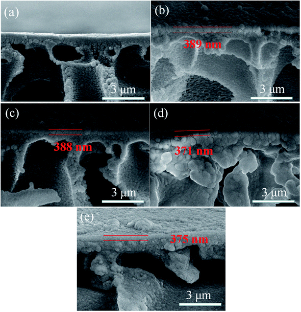
The cross-section morphologies of the prepared membranes were shown in Fig. 7. Compared with HPAN substrate, the prepared nanofiltration membranes presented porous substrate with PA selective layer tightly covering on the top surface. And no interfacial defects between the selective layer and support layer could be found, which could be attributed to the electrostatic interaction between the substrate and PIP indicating the good interfacial compatibility. The thickness of the PA selective layer for each membrane was around 380 nm, which was marked by the red parallel lines in the images.
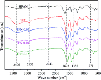
![[triple bond, length as m-dash]](https://www.rsc.org/images/entities/char_e002.gif) N in HPAN substrate.25 The absorption peaks appeared at 1623 and 1385 cm−1 in TFC and TFN membranes were related to –C
N in HPAN substrate.25 The absorption peaks appeared at 1623 and 1385 cm−1 in TFC and TFN membranes were related to –C![[double bond, length as m-dash]](https://www.rsc.org/images/entities/char_e001.gif) O and –C–N in amide groups, respectively,12,26 which indicated the PA layer was successfully fabricated on HPAN substrate after interfacial polymerization. The absorption peak at 771 cm−1 due to Zr–O could only be observed in TFN membranes,12 indicating the existence of UiO-66-NH2-PC on TFN membrane surfaces.
O and –C–N in amide groups, respectively,12,26 which indicated the PA layer was successfully fabricated on HPAN substrate after interfacial polymerization. The absorption peak at 771 cm−1 due to Zr–O could only be observed in TFN membranes,12 indicating the existence of UiO-66-NH2-PC on TFN membrane surfaces.
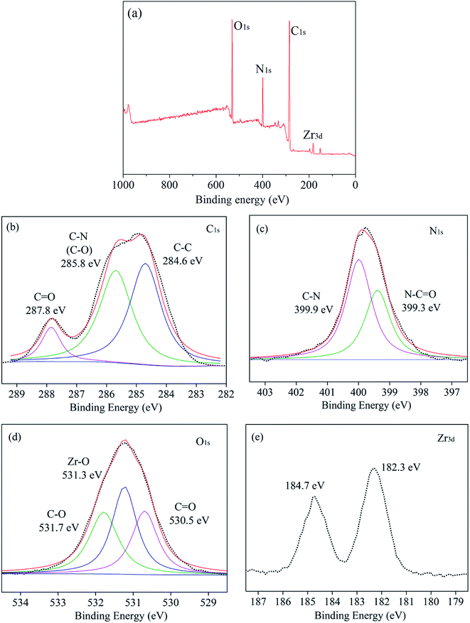
XPS measurement was used to further characterize the chemical structure of TFN membranes. The XPS survey spectra of TFN-0.10 were shown in Fig. 9. As shown in Fig. 9(a), the chemical elements of TFN-0.10 included carbon, oxygen, nitrogen and zirconium. The high-resolution XPS spectrum of each element was shown in Fig. 9(b–e). The XPS spectrum of C 1s could be resolved into 3 peaks at 287.8, 285.8, and 284.6 eV, which were attributed to C![[double bond, length as m-dash]](https://www.rsc.org/images/entities/char_e001.gif) O, C–N or C–O, and C–C, respectively.27,28 The N 1s spectrum could be fitted to two peaks at 399.9 and 399.3 eV which were assigned to C–N in PIP monomer and N–C
O, C–N or C–O, and C–C, respectively.27,28 The N 1s spectrum could be fitted to two peaks at 399.9 and 399.3 eV which were assigned to C–N in PIP monomer and N–C![[double bond, length as m-dash]](https://www.rsc.org/images/entities/char_e001.gif) O in polyamide, respectively indicating the polyamide selective layer successfully formed. The O spectrum could be fitted to 3 peaks at 531.7, 531.3, and 530.5 eV, respectively. The peak at 531.7 eV was ascribed to C–O of carboxyl groups from MOF nanoparticles and hydrolyzed acyl chloride groups in TMC. The peak at 531.3 eV was ascribed to Zr–O of MOF nanoparticles, and the peak at 530.5 eV was ascribed to C
O in polyamide, respectively indicating the polyamide selective layer successfully formed. The O spectrum could be fitted to 3 peaks at 531.7, 531.3, and 530.5 eV, respectively. The peak at 531.7 eV was ascribed to C–O of carboxyl groups from MOF nanoparticles and hydrolyzed acyl chloride groups in TMC. The peak at 531.3 eV was ascribed to Zr–O of MOF nanoparticles, and the peak at 530.5 eV was ascribed to C![[double bond, length as m-dash]](https://www.rsc.org/images/entities/char_e001.gif) O from acylamino, carboxyl groups and MOF nanoparticles in selective layer. The Zr element showed two peaks at 184.7 and 182.3 eV. From Fig. 9(d and e), the existence of Zr element and Zr–O bonds revealed the UiO-66-NH2-PC nanoparticles loaded on the membrane surface after interfacial polymerization process.
O from acylamino, carboxyl groups and MOF nanoparticles in selective layer. The Zr element showed two peaks at 184.7 and 182.3 eV. From Fig. 9(d and e), the existence of Zr element and Zr–O bonds revealed the UiO-66-NH2-PC nanoparticles loaded on the membrane surface after interfacial polymerization process.
| Membrane | TFC | TFN-0.05 | TFN-0.10 | TFN-0.15 |
|---|---|---|---|---|
| Ra (nm) | 15.0 | 24.6 | 30.6 | 37.8 |
| Rq (nm) | 19.0 | 32.1 | 39.1 | 46.9 |
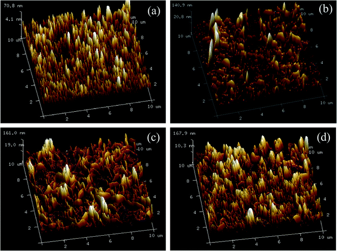
The surface topography images of the prepared membranes also displayed “ridge and valley” morphologies, which was in accordance with FE-SEM images of the membrane surfaces in Fig. 6. As shown in Table 1, the Ra and Rq value increased with the increase of UiO-66-NH2-PC loading amount indicating the membranes became rougher after loading nanoparticles on membrane surface. The same phenomena about other nanomaterials were also achieved in the previous researches.33,34 The rougher membrane surface could provide larger surface area for mass transfer to obtain a higher permeability.
3.3 Nanofiltration performance of the prepared membranes
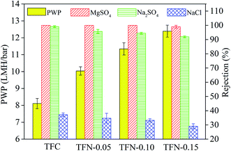
As displayed in Fig. 15, the pure water permeability (PWP) increased from 8.1 LMH bar−1 for TFC membrane to 12.4 LMH bar−1 for TFN-0.15. The increased PWP was largely ascribed to the following factors: firstly, the adding of nanomaterial increased the membrane free volume because the added nanomaterial could interfere with polyamide chain packing;37 secondly, the intrinsic nanopores of the UiO-66-NH2-PC material and the formation of nanomaterial/polyamide interfaces could supply additional passageways for water passing through the membrane.9 Due to the above reasons, the permeability increased continuously with the increase of UiO-66-NH2-PC loading amount.
The rejection properties of the prepared membrane slightly decreased continuously with the increase of UiO-66-NH2-PC loading amount. That was ascribed to the formation of the nanomaterial/polyamide interfaces, which led to the leakage of solute passing through the membrane selective layers. The decrease of rejection properties in TFN membranes is a general phenomenon that was reported in other literature.38–40 It should be noted that all the prepared membranes exhibited the rejection property order of MgSO4 > Na2SO4 > NaCl, which could be explained by the rejection mechanism of nanofiltration membranes. It was known that the membrane rejection property was based on both size sieving effect and Donnan effect.41 The hydrated diameters of the salt ions were Mg2+ (0.86 nm) > Na+ (0.72 nm), SO42− (0.76 nm) > Cl− (0.66 nm).42 All the membranes showed negatively zeta potential and thus could repulse the same charged SO42− and Cl−, but the divalent ions were easy to be rejected than monovalent ions due to the stronger electronegativity and larger hydrated diameter. So the membranes exhibited higher rejection property of sulfate than chlorate. The rejection of MgSO4 > Na2SO4 was due to the larger hydrated diameter of Mg2+, which was in accordance with the previous research in other literature.10
When the UiO-66-NH2-PC loading amount was within 0.10% w/v, the MgSO4 rejection was about 100% and NaCl rejection was above 30%, so the UiO-66-NH2-PC loading amount of 0.10% w/v was an acceptable value.
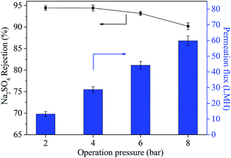
| Jw = A(Δp − Δπ) |
The Jw represents water flux and A represents permeability parameter. Δp and Δπ refer to the operation pressure and osmotic pressure, respectively. It could be found that Jw was the function of Δp and there was a linear relationship between Jw and Δp.43 It was worth noting that the permeation flux at the operation pressure of 4 bar was 28.7 LMH, which was much lower than the pure water permeability of 11.3 LMH bar−1. This was attributed to the existence of osmotic pressure (Δπ) caused by the concentration polarization between feed side and the permeation side of the membrane.
The operation pressure also influenced the rejection property of TFN-0.10 membrane. With the increase of operation pressure the Na2SO4 rejection decreased continuously, which was in accordance with the reported literature.15 This phenomenon could be explained by the formation of voids at nanoparticle/polyamide interfaces.32 Considering the mobility difference between rigid inorganic nanoparticles and flexible organic polyamide matrix, high pressure might tear and weaken the interfacial interaction between nanoparticles and polyamide matrix, because rigid inorganic nanoparticles could not move flexibly and change shape with polyamide chain synchronously and hence led to the formation of voids at their interfaces.
4 Conclusion
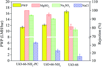
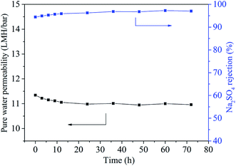
In this study, the surface modified UiO-66-NH2 nanoparticles were dispersed in organic phase and introduced into the preparation process of TFN membranes. The surface modification could increase the dispersibility of the synthesized UiO-66-NH2 nanoparticles and hence reduce the aggregation of nanoparticles in organic phase to prepare high performance nanofiltration membranes. The prepared TFC and TFN membranes displayed typical “ridge-valley” shaped Turing structure surface morphology. The SEM, ATR-FTIR and XPS characterization demonstrated the polyamide layer was fabricated on HPAN substrates and the modified UiO-66-NH2 nanoparticles were loaded on the membrane surfaces. Hydrophobicity, surface roughness and zeta potential of TFN membrane increased compared with TFC membrane. The TFN membranes showed higher water permeability and slightly lower rejection properties with the increase of UiO-66-NH2-PC concentration in organic phase. Compared with the TFN membranes prepared with pristine UiO-66 and UiO-66-NH2, the TFN membrane prepared with modified UiO-66-NH2 displayed higher salt rejection properties due to the better dispersibility after modification. Furthermore, the membrane performance was stable in the long-term operation test.Conflicts of interest
There are no conflicts to declare.Acknowledgements
This work was supported by the National Natural Science Foundation of China (No. 21908040 and 21878068), the Natural Science Foundation of Hebei Province (B2017202056), the Program for Top 100 Innovative Talents in Colleges and Universities of Hebei Province (SLRC2017029) and Hebei High Level Personnel of Support Program (A2016002027).References
- W. J. Koros and R. P. Lively, Water and beyond: expanding the spectrum of large-scale energy efficient separation processes, AIChE J., 2012, 58, 2624–2633 CAS.
- M. Padaki, R. S. Murali, M. S. Abdullah, N. Misdan, A. Moslehyani, M. A. Kassim, N. Hilal and A. F. Ismail, Membrane technology enhancement in oil–water separation. A review, Desalination, 2015, 357, 197–207 CrossRef CAS.
- C. Castel and E. Favre, Membrane separations and energy efficiency, J. Membr. Sci., 2018, 548, 345–357 CAS.
- A. Ahmad, D. Lokhat, Y. Wang and M. Rafatullah, Recent Advances in Nanofiltration Membrane Techniques for Separation of Toxic Metals from Wastewater, Nanotechnology for Sustainable Water Resources, 2018, pp. 477–500 Search PubMed.
- H. B. Park, J. Kamcev, L. M. Robeson, M. Elimelech and B. D. Freeman, Maximizing the right stuff: the trade-off between membrane permeability and selectivity, Science, 2017, 356, eaab0530 Search PubMed.
- B.-H. Jeong, E. M. Hoek, Y. Yan, A. Subramani, X. Huang, G. Hurwitz, A. K. Ghosh and A. Jawor, Interfacial polymerization of thin film nanocomposites: a new concept for reverse osmosis membranes, J. Membr. Sci., 2007, 294, 1–7 CAS.
- M. Paul and S. D. Jons, Chemistry and fabrication of polymeric nanofiltration membranes: a review, Poly, 2016, 103, 417–456 CAS.
- J. L. Rowsell and O. M. Yaghi, Metal–organic frameworks: a new class of porous materials, Microporous Mesoporous Mater., 2004, 73, 3–14 CrossRef CAS.
- X. Cheng, X. Jiang, Y. Zhang, C. H. Lau, Z. Xie, D. Ng, S. J. Smith, M. R. Hill and L. Shao, Building Additional Passageways in Polyamide Membranes with Hydrostable Metal Organic Frameworks To Recycle and Remove Organic Solutes from Various Solvents, ACS Appl. Mater. Interfaces, 2017, 9, 38877–38886 CrossRef CAS PubMed.
- Y. He, Y. P. Tang, D. Ma and T.-S. Chung, UiO-66 incorporated thin-film nanocomposite membranes for efficient selenium and arsenic removal, J. Membr. Sci., 2017, 541, 262–270 CrossRef CAS.
- G. Lai, W. Lau, S. Gray, T. Matsuura, R. J. Gohari, M. Subramanian, S. Lai, C. Ong, A. Ismail and D. Emazadah, A practical approach to synthesize polyamide thin film nanocomposite (TFN) membranes with improved separation properties for water/wastewater treatment, J. Mater. Chem. A, 2016, 4, 4134–4144 CAS.
- M. Golpour and M. Pakizeh, Preparation and characterization of new PA-MOF/PPSU-GO membrane for the separation of KHI from water, Chem. Eng. J., 2018, 345, 221–232 CAS.
- R. Zhang, S. Ji, N. Wang, L. Wang, G. Zhang and J. R. Li, Coordination-driven in situ self-assembly strategy for the preparation of metal–organic framework hybrid membranes, Angew. Chem., Int. Ed., 2014, 53, 9775–9779 CrossRef CAS PubMed.
- N. Wang, T. Liu, H. Shen, S. Ji, J. R. Li and R. Zhang, Ceramic tubular MOF hybrid membrane fabricated through in situ layer-by-layer self-assembly for nanofiltration, AIChE J., 2016, 62, 538–546 CrossRef CAS.
- J. Zhu, L. Qin, A. Uliana, J. Hou, J. Wang, Y. Zhang, X. Li, S. Yuan, J. Li and M. Tian, Elevated performance of thin film nanocomposite membranes enabled by modified hydrophilic MOFs for nanofiltration, ACS Appl. Mater. Interfaces, 2017, 9, 1975–1986 CrossRef CAS PubMed.
- X. Guo, D. Liu, T. Han, H. Huang, Q. Yang and C. Zhong, Preparation of thin film nanocomposite membranes with surface modified MOF for high flux organic solvent nanofiltration, AIChE J., 2017, 63, 1303–1312 CrossRef CAS.
- A. Schaate, P. Roy, A. Godt, J. Lippke, F. Waltz, M. Wiebcke and P. Behrens, Modulated synthesis of Zr-based metal–organic frameworks: from nano to single crystals, Chem.–Eur. J., 2011, 17, 6643–6651 CrossRef CAS PubMed.
- Z. Hu, Y. Peng, Z. Kang, Y. Qian and D. Zhao, A modulated hydrothermal (MHT) approach for the facile synthesis of UiO-66-type MOFs, Inorg. Chem., 2015, 54, 4862–4868 CrossRef CAS PubMed.
- L. Wan, C. Zhou, K. Xu, B. Feng and A. Huang, Synthesis of highly stable UiO-66-NH2 membranes with high ions rejection for seawater desalination, Microporous Mesoporous Mater., 2017, 252, 207–213 CrossRef CAS.
- C. Van Goethem, R. Verbeke, S. Hermans, R. Bernstein and I. Vankelecom, Controlled positioning of MOFs in interfacially polymerized thin-film nanocomposites, J. Mater. Chem. A, 2016, 4, 16368–16376 RSC.
- H. Wu, B. Tang and P. Wu, Optimizing polyamide thin film composite membrane covalently bonded with modified mesoporous silica nanoparticles, J. Membr. Sci., 2013, 428, 341–348 CrossRef CAS.
- W. Fang, L. Shi and R. Wang, Mixed polyamide-based composite nanofiltration hollow fiber membranes with improved low-pressure water softening capability, J. Membr. Sci., 2014, 468, 52–61 CrossRef CAS.
- Z. Tan, S. Chen, X. Peng, L. Zhang and C. Gao, Polyamide membranes with nanoscale Turing structures for water purification, Science, 2018, 360, 518–521 CrossRef CAS PubMed.
- Y. Shen, H. Wang, X. Zhang and Y. Zhang, MoS2 nanosheets functionalized composite mixed matrix membrane for enhanced CO2 capture via surface drop-coating method, ACS Appl. Mater. Interfaces, 2016, 8, 23371–23378 CrossRef CAS PubMed.
- H. Zhang, H. Mao, J. Wang, R. Ding, Z. Du, J. Liu and S. Cao, Mineralization-inspired preparation of composite membranes with polyethyleneimine–nanoparticle hybrid active layer for solvent resistant nanofiltration, J. Membr. Sci., 2014, 470, 70–79 CrossRef CAS.
- Q.-F. An, W.-D. Sun, Q. Zhao, Y.-L. Ji and C.-J. Gao, Study on a novel nanofiltration membrane prepared by interfacial polymerization with zwitterionic amine monomers, J. Membr. Sci., 2013, 431, 171–179 CrossRef CAS.
- L. Bai, Y. Liu, N. Bossa, A. Ding, N. Ren, G. Li, H. Liang and M. R. Wiesner, Incorporation of Cellulose Nanocrystals (CNCs) into the Polyamide Layer of Thin-Film Composite (TFC) Nanofiltration Membranes for Enhanced Separation Performance and Antifouling Properties, Environ. Sci. Technol., 2018, 52, 11178–11187 CrossRef CAS PubMed.
- S.-H. Park, Y.-S. Ko, S.-J. Park, J. S. Lee, J. Cho, K.-Y. Baek, I. T. Kim, K. Woo and J.-H. Lee, Immobilization of silver nanoparticle-decorated silica particles on polyamide thin film composite membranes for antibacterial properties, J. Membr. Sci., 2016, 499, 80–91 CrossRef CAS.
- W. Lau, S. Gray, T. Matsuura, D. Emadzadeh, J. P. Chen and A. Ismail, A review on polyamide thin film nanocomposite (TFN) membranes: history, applications, challenges and approaches, Water Res., 2015, 80, 306–324 CAS.
- F. Yang, S. Zhang, D. Yang and X. Jian, Preparation and characterization of polypiperazine amide/PPESK hollow fiber composite nanofiltration membrane, J. Membr. Sci., 2007, 301, 85–92 CrossRef CAS.
- S. Wu, Y. Ge, Y. Wang, X. Chen, F. Li, H. Xuan and X. Li, Adsorption of Cr(VI) on nano Uio-66-NH2 MOFs in water, Environ. Technol., 2018, 39, 1937–1948 CrossRef CAS PubMed.
- H. Liu, J. Gao, G. Liu, M. Zhang and Y. Jiang, Enhancing permeability of thin film nanocomposite (TFN) membranes via covalent linking of polyamide with the incorporated metal–organic frameworks, Ind. Eng. Chem. Res., 2019, 58, 8772–8783 CAS.
- Y. Xu, X. Gao, X. Wang, Q. Wang, Z. Ji, X. Wang, T. Wu and C. Gao, Highly and stably water permeable thin film nanocomposite membranes doped with MIL-101 (Cr) nanoparticles for reverse osmosis application, Materials, 2016, 9, 870 CrossRef.
- H. Wu, B. Tang and P. Wu, Optimization, characterization and nanofiltration properties test of MWNTs/polyester thin film nanocomposite membrane, J. Membr. Sci., 2013, 428, 425–433 CrossRef CAS.
- S. Yu, M. Liu, Z. Lü, Y. Zhou and C. Gao, Aromatic-cycloaliphatic polyamide thin-film composite membrane with improved chlorine resistance prepared from m-phenylenediamine-4-methyl and cyclohexane-1,3,5-tricarbonyl chloride, J. Membr. Sci., 2009, 344, 155–164 CrossRef CAS.
- S. Lin, H. Huang, Y. Zeng, L. Zhang and L. a. Hou, Facile surface modification by aldehydes to enhance chlorine resistance of polyamide thin film composite membranes, J. Membr. Sci., 2016, 518, 40–49 CrossRef CAS.
- S. Bano, A. Mahmood, S.-J. Kim and K.-H. Lee, Graphene oxide modified polyamide nanofiltration membrane with improved flux and antifouling properties, J. Mater. Chem. A, 2015, 3, 2065–2071 RSC.
- I. H. Aljundi, Desalination characteristics of TFN-RO membrane incorporated with ZIF-8 nanoparticles, Desalination, 2017, 420, 12–20 CrossRef CAS.
- C. Wang, Z. Li, J. Chen, Z. Li, Y. Yin, L. Cao, Y. Zhong and H. Wu, Covalent organic framework modified polyamide nanofiltration membrane with enhanced performance for desalination, J. Membr. Sci., 2017, 523, 273–281 CrossRef CAS.
- H. Wu, H. Sun, W. Hong, L. Mao and Y. Liu, Improvement of polyamide thin film nanocomposite membrane assisted by tannic acid–FeIII functionalized multiwall carbon nanotubes, ACS Appl. Mater. Interfaces, 2017, 9, 32255–32263 CrossRef CAS PubMed.
- C. Hu, Z. Liu, X. Lu, J. Sun, H. Liu and J. Qu, Enhancement of the Donnan effect through capacitive ion increase using an electroconductive rGO-CNT nanofiltration membrane, J. Mater. Chem. A, 2018, 6, 4737–4745 CAS.
- X. You, H. Wu, Y. Su, J. Yuan, R. Zhang, Q. Yu, M. Wu, Z. Jiang and X. Cao, Precise nanopore tuning for a high-throughput desalination membrane via co-deposition of dopamine and multifunctional POSS, J. Mater. Chem. A, 2018, 6, 13191–13202 CAS.
- S. J. Zaidi, F. Fadhillah, Z. Khan and A. Ismail, Salt and water transport in reverse osmosis thin film composite seawater desalination membranes, Desalination, 2015, 368, 202–213 CrossRef CAS.
- G. Férey and C. Serre, Large breathing effects in three-dimensional porous hybrid matter: facts, analyses, rules and consequences, Chem. Soc. Rev., 2009, 38, 1380–1399 Search PubMed.
Footnote |
| † Electronic supplementary information (ESI) available. See DOI: 10.1039/c9ra09672h |
| This journal is © The Royal Society of Chemistry 2020 |

